STRUMIN LiteMESH Guide

P a g e | 1
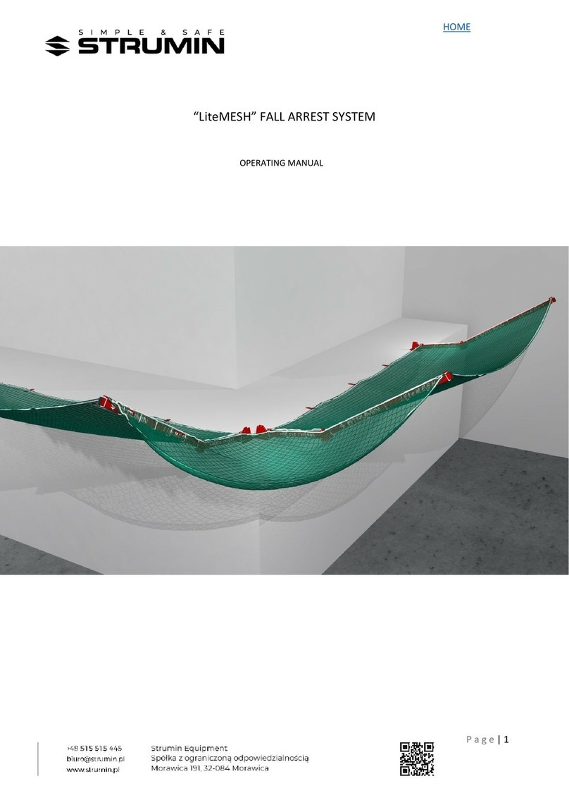
“LiteMESH” FALL ARREST SYSTEM
TECHNICAL DOCUMENTATION AND ASSEMBLY MANUAL

P a g e | 2
1.0
TECHNICAL DOCUMENTATION, GENERAL DESCRIPTION OF THE LiteMESH SYSTEM
The LiteMESH fall arrest system is a steel construction consisting of a few basic elements:
•
SVIWEL ARM OF THE CONSOLE
•
CONSOLE’S HOOLDER
•
MODULE’S NET 6×3M (4×3M)
•
CORNER NET 3×3M
•
CONNECTING LINE Ø8
•
STRECHING LINE Ø8
•
STRECHING HOLDER
•
ASSEMBLY ADAPTER OF THE CONSOLE “H”
THE FALL ARREST SYSTEM is available in a few configurations which were
presented in chapter 2.0
The LITEMESH modules can work with different elements of the system, i.e.
ASSEMBLY ADAPTERS, CORNER NETS AND SNETS.
The use of a given solution depends on individual conditions of the construction site.
The corrosion protection of the elements is provided by a system of lacquered layers.

P a g e | 3
CONSOLE’S HOLDER
CONNECTING LINE Ø8
MODULE’S NET 6×3M (4×3M)
LiteMESH MODULE
Console’s swivel arm
CORNER NET 3×3M
1.1
THE CONSTRUCTION OF THE LiteMESH SYSTEM.

P a g e | 4
Console’s assembly adapter “H”
Stretching holder
1.1
CONSTRUCTION OF THE LITEMESH SYSTEM.

P a g e | 5
1.1 CONSTRUCTION OF THE LiteMESH SYSTEM.
STRECHING LINE Ø8
STRECHING HOLDER

P a g e | 6
Moveable adjusted console
Edge line Ø12
Mosquito net
Polypropylene net Ø5 (6×6 cm)
1.2
LiteMESH FALL ARREST SYSTEM'S MODULE
The LiteMESH system's module consists of a moveable, regulated console and
a polypropylene net (6×3 m or 4×3 m).
The console consists of a universal assembly holder and a swivel arm. The arm’s opening angle can
be adjusted from 90° to 180°.
The net consists of two integrated nets of which one is used to catch large objects and the other one
(mosquito net) catches smaller elements, i.e. tools, hardcore and even semi-liquid materials (concrete,
mortar) etc.
Along the edge of the net there is an integrated polypropylene line (Ø12 and the strength of 30 kN).
The net used in the system was designed in accordance with the EN-1263-1_2015-02E standard:
TYPE S, A2 Q100. It means that it is a A2-class net that absorbs min. 2300 J of energy. The allowed
maximum fall height for objects is below 2 m.
LiteMESH MODULE
ATTENTION: “One module” consists of one
console and one net.
The figures show two consoles to provide better
understanding of this documentation.

P a g e | 7
1.3
MOVEABLE ADJUSTED CONSOLE LiteMESH
The console consists of the universal assembly holder and the adjustable
moveable arm. The arm is divided by a joint into two asymmetrical parts.
The arm is equipped with two holders of the edge line.
The console can be configured for different joint's opening angles. It allows to use the
device in different projects that take advantage of the flexibility of the LiteMESH
system.
Joint
The adjusted moveable arm
The universal assembly holder
The edge line's holder

P a g e | 8
1.4
UNIVERSAL ASSEMBLY HOLDER LiteMESH
The assembly holder is used to adjust the position of the moveable arm (attached to
the ceiling or wall). It can be fasten to the ceiling with four screws to concrete, i.e. FBS
10×100.
Due to the forces influencing the arm an screws no other
types of fixing shall be used
The floor foot has to be anchored to the floor with concrete screws that provide the
durability of 10 kN.
The adapter was designed in such a way, as to allow its assembly to the top, front or
bottom of the floor. The figures below show three basic configurations of the adapter.
The tools needed to perform the assembly are a hammer drill, a Ø10 bit and an impact
wrench.

P a g e | 9
1.5
STRETCHING AND EDGE LINE HOLDER
The safety net is additionally attached to the floor along its edge (with connectors) –
between neighbouring consoles. The recommended number of connectors depends
on individual needs in a given situation. It is generally assumed that the distance
between the assembly points shall be no bigger than 3 m.
If it is necessary because of the conditions during the assembly, the connectors
should be attached closer to one another, so they can provide sufficient adherence to
the floor’s edge and the edge line with the net.
The connectors are also used for stretching the most extreme consoles.

P a g e | 10
1.6
“H” CONSOLE ASSEMBLY ADAPTER
The assembly adapter of the console allows to assemble the universal attaching holder to different types of
poles, balks etc. The figures below show an example of the assembly to metal constructional elements of a
building.
Because the assembly of the adapter is performed with polypropylene stripes, there is no need for any
screw connections between the construction and the adapter. Thanks to it, the assembly of the system
is quicker and cheaper.

P a g e | 11
,
1.7
SCREWS FOR CONCRETE
Characteristics:
•
Self-tapping screws for concrete,
•
Ø12 thread,
•
Ø10 mandrel,
•
Ø10 hole (drilled in concrete)
•
galvanised,
•
100 mm length,
•
Assembled with
a screwdriver
(key No. 15),

P a g e | 12
2.0
CONFIGURATION OF THE LiteMESH SYSTEM
The idea of the LiteMESH fall-arrest system is creating a simple technical solution which protects from
falling objects while providing many configuration options that allow to adjust the system to the
customer’s requirements, conditions etc.
The system is based on multifunctional elements which (thanks to their universality) allow to use
different configurations of the same elements of the system.
2.1
LiteMESH STRAIGHT – WALL ASSEMBLY

P a g e | 13
2.2
LiteMESH “BENT” – WALL ASSEMBLY

P a g e | 14
2.3
LiteMESH “BENT” –FLOOR ASSEMBLY

P a g e | 15
2.4
LiteMESH “BENT” – POLE ASSEMBLY (STEEL PROFILE)

P a g e | 16
2.5
LiteMESH “BENT” –TOP ASSEMBLY

P a g e | 17
2.6
LiteMESH “BENT” – CORNER NET

P a g e | 18
3.0
ASSEMBLY INSTRUCTION
3.1
ASSEMBLY INSTRUCTION OF A UNIVERSAL ASSEMBLY HOLDER
The assembly of a universal assembly holder is performed with the use of four
screws for concrete HUS 10x100.
Ø10 and ~16 cm deep holes shall be drilled in the surface.
The surface where the drilling is performed shall provide the minimum strength of Q=10 kN and
the minimum depth shall be 10 cm.
Assembly the socket to the surface with screws using a screwdriver.
Attention –the assembly holder is equipped with six assembly holes to provide universality – the
holes are used in different configurations, depending on the assembly position (see p. 1.4).
Attention – in practical assembly solutions, the most extreme consoles are assembled with the use of
all six assembly holes. It allows to fix the console within the scope of the Z-axis movements (see the
figure below).

P a g e | 19
3.2
MOVEABLE ARM ASSEMBLY INSTRUCTION
… the most extreme consoles are
assembled with the use of all six
assembly holes …
… the most extreme consoles are
assembled with the use of all six
bl h l

P a g e | 20
The moveable arm is attached to the universal holder with one M12 screw and additional M12 screw
locking the arm from the bottom.
In the same way are assembled the elements of the moveable arm in the swivel.
Other manuals for LiteMESH
1
Table of contents
Other STRUMIN Safety Equipment manuals
Popular Safety Equipment manuals by other brands

TOOLCRAFT
TOOLCRAFT 1781067 operating instructions

schmersal
schmersal AZM300B-I1-ST1P2P-A Instructions for operation

Specified Technologies
Specified Technologies EZ-PATH MAX EZD44 Installation sheet

LAHTI PRO
LAHTI PRO L1501300 user manual

Petzl
Petzl P50A Specific information

Teknoware
Teknoware STEEL installation guide