Stuart Turner Pulse Trade 25/80-180 Guide
STUART
Installation, Operation & Maintenance
Instructions
Please leave this instruction booklet in a safe place as it contains
important warranty, maintenance and safety information
Read this manual carefully before commencing installation.
This manual covers the following products:
Stuart Pulse Trade 25/80-180 Circulator | Part No. 47540
Stuart Pulse Trade 25/100-180 Circulator | Part No. 47542
Stuart Pulse Trade 25/120-180 Circulator | Part No. 47544
Please note images are representative only and may not portray
your model

CONTENTS
1PRODUCT OVERVIEW...............................................................................................3
2SAFETY INSTRUCTIONS ............................................................................................4
3CHECKLIST ................................................................................................................ 7
4TRANSPORT AND STORAGE.....................................................................................8
5KEY FEATURES...........................................................................................................9
6PUMP SETTINGS ...................................................................................................... 10
7PWM FUNCTION...................................................................................................... 14
8FILLING AND VENTING THE SYSTEM...................................................................... 21
9RELATION BETWEEN PUMP SETTING AND CAPACITY..........................................22
10 CAPACITY CHARACTERISTICS ...............................................................................23
11 ASSEMBLY................................................................................................................24
12 ELECTRICAL CONNECTION ....................................................................................26
13 MAINTENANCE AND SERVICE................................................................................. 27
14 FAULTS, CAUSES AND REMEDIES...........................................................................28
15 DISPOSAL.................................................................................................................30
16 NOTES...................................................................................................................... 31
17 PRODUCT WARRANTY ...........................................................................................33
18 DECLARATION OF CONFORMITY ...........................................................................34

3
1PRODUCT OVERVIEW
1.1 Product Description
Our Stuart Pulse Trade Circulators features a robust cast iron pump housing
and is ideal for the transfer of liquid within systems for hot-water heating, air-
conditioning and ventilation.
This circulator features variable speed controls to constantly measure pressure
and flow and adjust the speed according to the set operating mode.
1.2 Application
The PULSE high-efficiency pumps are designed for circulating hot water in
central heating systems and are also suitable for pumping low-viscosity media
in the industrial and commercial sector. They also can be used in solar
technology systems.

4
2SAFETY INSTRUCTIONS
2.1 General
These operating instructions are part of the product and contain basic
information that must be observed during assembly, installation, operation
and maintenance. For this reason it must be read by the installer and the
responsible qualified personnel or the operator before performing assembly
works.
Not only the general safety instructions mentioned in point 2 must be
observed, but also the special safety instructions mentioned in the other
sections.
A copy of the EU Declaration of Conformity is provided with these
instructions. In case of a modification, which has not been agreed with us
beforehand, the declaration loses its validity.
2.2 Labelling of symbols in the operating instructions
General danger symbol Warning! Danger of personal injury! The
existing regulations for accident prevention must be observed.
Warning! Danger due to electrical voltage! Danger due to electrical
energy must be excluded. Observe the instructions in local or
general regulations (e.g. IEC, VDE, etc.) and those of the local energy
suppliers.
2.3 Personnel qualification
The personnel, who is carrying out assembly, operation and
maintenance works must provide appropiate qualifications.
The area of responsibility, competence and supervision of the personnel must
be ensured by the operator. If personnel do not provide the required know-
how, they must be trained or instructed accordingly.
This device can be used by
children
aged from 8 years and above, as well as
by persons with reduced physical, sensory or mental capabilities or lack of
experience and know-how, only if they have been given supervision or
instruction concerning use of the device in a safe way and if they understand
the hazards involved.
Children
must not play with the device. Cleaning and
user maintenance works
must not be carried out by
children
without
supervision.

5
2.4 Dangers, if the safety instructions are not observed
Failure to observe the safety instructions may endanger persons, the
environment and the system. Failure to comply with the safety instructions
will result in the loss of any claims for damages.
Potential dangers include:
•dangers to persons due to electrical and mechanical effects
•failure of important functions of the system
•danger to the environment due to leakage of liquids as a result of a leak
•failure of prescribed repair and maintenance works
2.5 Safety-conscious work
Observe the safety instructions detailed in these operating instructions, along
with the current national accident prevention regulations. Should the system
operator also have their own internal regulations, these must also be
observed.
2.6 Safety instructions for the operator
•Any protection against contact with moving parts must not be removed
or disabled, while the system is in operation.
•If liquids leak out, they must be collected or diverted in such a way, that
no danger to persons or environment can arise.
•Hazards due to electrical energy must be excluded.
•For this purpose observe the instructions in local or general regulations
(e.g. VDE, etc.) and those of the local energy suppliers.
•If hazards should occur in the system due to hot or cold parts, these must
be provided with a touch guard.
•Highly flammable substances must be kept away from the product.

6
2.7 Safety instructions for assembly and maintenance works
The system operator is responsible for ensuring that all assembly and
maintenance works are carried out by qualified personnel. They must have
previously familiarised themselves with the product, using the operting
isntructions. Conducting of works on the pump is only permitted when the
system is shut down.
Ensure that the device is securely disconnected from the power supply.
Disconnect the device plug to achieve this. Prescribed instructions for
shutting down the device can be found in the operating instructions. After
completion of the works, all protective devices, such as touch guard, must be
refitted in accordance with the regulations.
2.8 Unauthorised modification and use of spare parts
Modifiactions or alterations of the product are only permitted after prior
consultation with the manufacturer. Use only original spare parts for repairs.
Only accesories approved by the manufacturer can be used. If other parts are
used, any liability of the manufacturer for the resulting consequences is
excluded.
2.9 Inadmissible operating modes
If the pump is disconnected from the power supply, wait at least 1
minute before switching it on again. Otherwise, the pump's inrush
current limit has no effect, which can lead to functional errors or
damage to any connected heating controller. The pump's operational safety
can only be ensured if it is used as intended. Point 4 ot these operating
instructions must be observed. Ensure compliance with the limit values
detailed in the technical data.

7
3CHECKLIST
IMPORTANT: With the appliance removed from its packaging check for any
damage prior to installation. If any damage is found contact Stuart Turner Ltd
within 24 hours of receipt.
Item Description Qty
A Instruction guide 1
B Pulse Trade Circulator 1
C Flat gaskets 2
D Mains cable 1
E Insulation 1
Your product may vary slightly from the photo above.

8
4TRANSPORT AND STORAGE
After receiving the product, inspect it immediately for damage caused in
transport. If any transport damage is found, this must be claimed by the
carrier.
Improper transport and storage can lead to personal injuries or
damages to the product.
•Protect the product against frost, moisture and damage during transport
and storage.
•Only carry the pump by the pump housing, and never by the connection
cable or terminal box.
•If the packaging has been softened by moisture, the pump may fall out
and cause severe injuries.

9
5KEY FEATURES
5.1 Technical data
Pulse Circulator Model
25/80-180
25/100-180
25/120-180
Maximum delivery head
8.0 m 10.0 m 12.0 m
Maximum flow rate
8000 l/h 9000 l/h 10000 l/h
Power consumption P1 (W)
80 W 120 W 180 W
Supply voltage
1 x 230V 50Hz
Emission sound pressure level
<43 dB(A)
EEI
≤ 0.23
Thermal class
TF 110
Ambient temperature
0 °C to 40 °C
Media temperature
+2 to 110 °C
Maximum system pressure
10 bar (1MPa)
Permitted pumped media
heating water according to VDI 2035
water/glycol mixture 1:1
Supply pressure Permitted range of temperature
Medium
Temperature
Minimum supply
pressure
Temp range at
max ambient
temperature
Permissible
medium
temperature
< 75 °C 0.05 bar 0.005
MPa 0.5 m
25 °C 5 °C to 110 °C
75 °C - 90 °C 0.3 bar 0.03 MPa
3.0 m
40 °C 5 °C to 95 °C
90 °C - 110 °C 1.1 bar 0.11 MPa
11.0 m
10
6PUMP SETTINGS
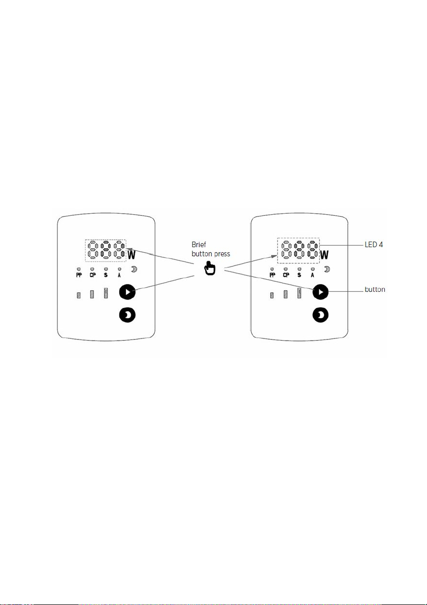
6.1 Button
All pump functions can be controlled with just two buttons. The button
switches the night reduction function on and off. The button controls the
operating modes. The selected operating mode is shown in the clear field of
the LED indicator.
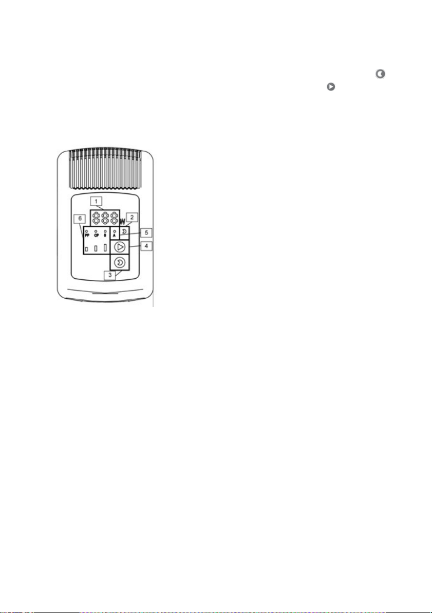
6.2 Control panel and LED display
1. Display of energy consumption in watts
2. Automatic night reduction display
3. Button for activating the automatic night
reduction
4. Operating mode selection button
5. Display for activated AUTO Smartadapt
mode
6. Display of the nine operating levels
(characteristics) of the pump
6.3 Selection of the operating mode and operating level
1. Constant speed mode I, II and III
In this operating mode, the pump rotates at a constant speed over the entire
characteristic curve.
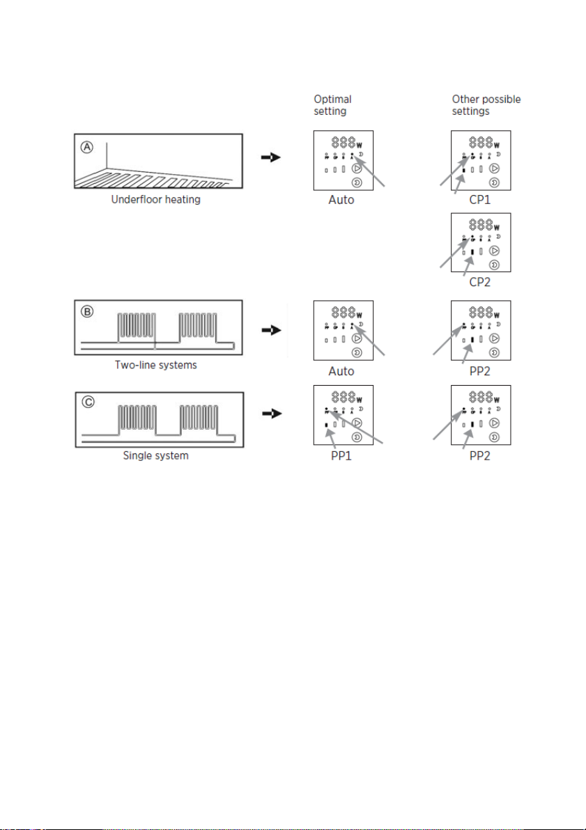
2. Constant pressure mode CP 1, CP 2, CP 3
In this control mode, the pressure generated by the pump is kept at a
constant level. This control mode is particularly suitable for use in underfloor
heating systems.
3. Proportional pressure mode PP1, PP2, PP3
In this mode the pump is controlled according to proportional-pressure
principle. In this case, the pressure generated by the pump adapts to the
changing flow rate. This operating mode is particularly suitable if the pump is
intended for use as a heating circulation pump.
4. AUTO Smart Adapt
The AUTO Smart Adapt function is designed for two-circuit heating systems
and underfloor heating systems. In this mode the pump performance adapts
automatically to the actual heat demand of the system. The adjustment of the
pump performance happens gradually and can take longer then a week. If the
power supply to the pump in interrupted, the pump saves the last settings
and resumes the adjustment as soon as the power supply is restored. On

11
delivery, the pump ist set to the AUTO Smart Adapt operating level. By
repeatedly briefly pressing of the selection button, the operating modes:
constant speed, constant pressure, proportional pressure and AUTO Smart
Adapt are switched through continously. The selected operating mode is
indicated by the corresponding LED with characteristic symbols.
No. of button
presses
Display Description Symbol
on display
0
AUTO
(factory
settings)
AUTO Smart Adapt
1 PP1 Minimum proportional pressure
control mode
2 PP2 Medium proportional pressure
control mode
3 PP3 Maximum proportional pressure
control mode
4 CP1 Minumum constant pressure
control mode
5 CP2 Medium constant pressure
control mode
6 CP3 Maximum constant pressure
control mode
7 I Constant speed control mode I
8 II Constant speed control mode II
9 III Constant speed control mode III
10 AUTO AUTO Smart Adapt

12
6.4 Automatic night reduction display
Display of means that automatic night reduction is activated.
6.5 Button for activating automatic night reduction
•By pressing the buton in section 3, automatic night reduction is
switched on or off.
•When the automatic night reduction is activated, the symbol lights up
in the display field 2.
The "Automatic Night Reduction" function is not available in the constant
speed levels.
6.6 Selection of the operating level
•Pressing the button switches between the operating levels.
•The factory configuration of Auto Smartadapt will be re-established by
pressing the button ten times.
6.7 Automatic night reduction
Conditions for automatic night reduction:
Pumps installed in gas boilers with low water capacity must never be set to
automatic night reduction:
If the heating system does not supply enough heat to the radiators, check
whether the automatic night reduction function is active. If necessary,
deactivate the automatic night reduction function.
To ensure that night reduction functions properly, the following requirements
must be met:
1.
The pump must be installed on the supply.
2.
Heating system must be equipeed with automatic temperature
adjustment on the supply.
How automatic night reduction works
Press the button to activate the night reduction function. If the adjacent
highlighted field is lit, the night reduction is activated and the pump
automatically switches between normal operation and night reduction.
Swiching depends on the flow temperature. The pump automatically switches
to night temperature reduction if the flow temperature drops by more than
10°-15°C in 1 hour. Switching to normal operating mode takes place
immediately as soon as the flow temperature rises again by 3°C.
The "Automatic Night Reduction" function is not available in the constant
speed levels.
13
6.8 Recommendations for the selection of the operating level
Factory setting = AUTO Smart Adapt
14
7PWM FUNCTION
7.1 Optional special function PWM input
This function allows the pump speed to be controlled by an external
controller. To use this function, the pump must have the appropriate input.
This external input can be recognized by an additional 3-pole connection
cable to which a suitable external control can be connected. After connecting
the PWM signal, the pump automatically switches to the PWM operating
mode. Switching is indicated by the indication P1 (heating mode) in the LED
field 4. The display field alternately shows the currently consumed electrical
power and the set PWM operating mode. By briefly pressing the button, you
can switch between the two PWM operating modes: heating mode P1 and
solar mode P2.
If the PWM signal is switched off or interrupted by a damage to the cable, the
pump automatically switches to the internal control logic. If, for safety
reasons, the pump is to switch to maximum speed in the event of a PWM
cable failure, stage III for constant speed adjustment must be set. This setting
ensures that the pump switches to maximum speed in the event of a failure of
the PWM control signal.
The maximum cable length is 3m! The polarity of the PWM cable must
correspond to:
BLACK = GND/earthing,
YELLOW = PWM feedback signal (Out)
RED = PWM control signal (In)
The signal line is galvanically insulated from the pump electronics by an
optocoupler. The PWM connection cable should be adapted to work with a
rated operating voltage of 230V AC.

15
Second side connected:
•Must reliably prevent direct contact with the cable conductors when
installed, i.e. the terminals must be touch-proof and the terminal
connections must be protected against unintentional contact by a fixed
cover.
•Must meet the requirements of protection class I (connection to
protective earthing). The device can be launched only after correct
connection of PWM signal.
The open-collector PWM output must be connected to the output electronics
via a suitable Pullup resistor. The operating voltage must be below 20V and
the input current must be between 2mA and 10mA. Or a voltage of 20V, the
recommended Pullup resistor value is: 4.7 kOhm - 10 kOhm 1/4W.
16
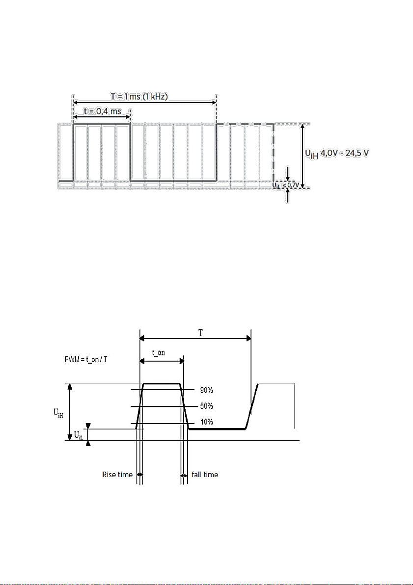
The PWM control signal is a digital signal in which the rotational speed
information is included in the pulse width. The control signal must meet the
following requirements:
Example of a PWM signal with a value of 40%:
PWM % = 100 * t / T
PWM % = 100 * 0.4 / 1 = 40 %
For T, frequencies between 200 Hz and 4 kHz are acceptable.
Permissible input current IH =: 3.5mA/4700Ω - 10mA/100 Ω
UIH input signal voltage level: 4.0V - 24.5V
Voltage level for LowLevel UIL † 0.7V
Rise time, signal fall time † T/1000
17
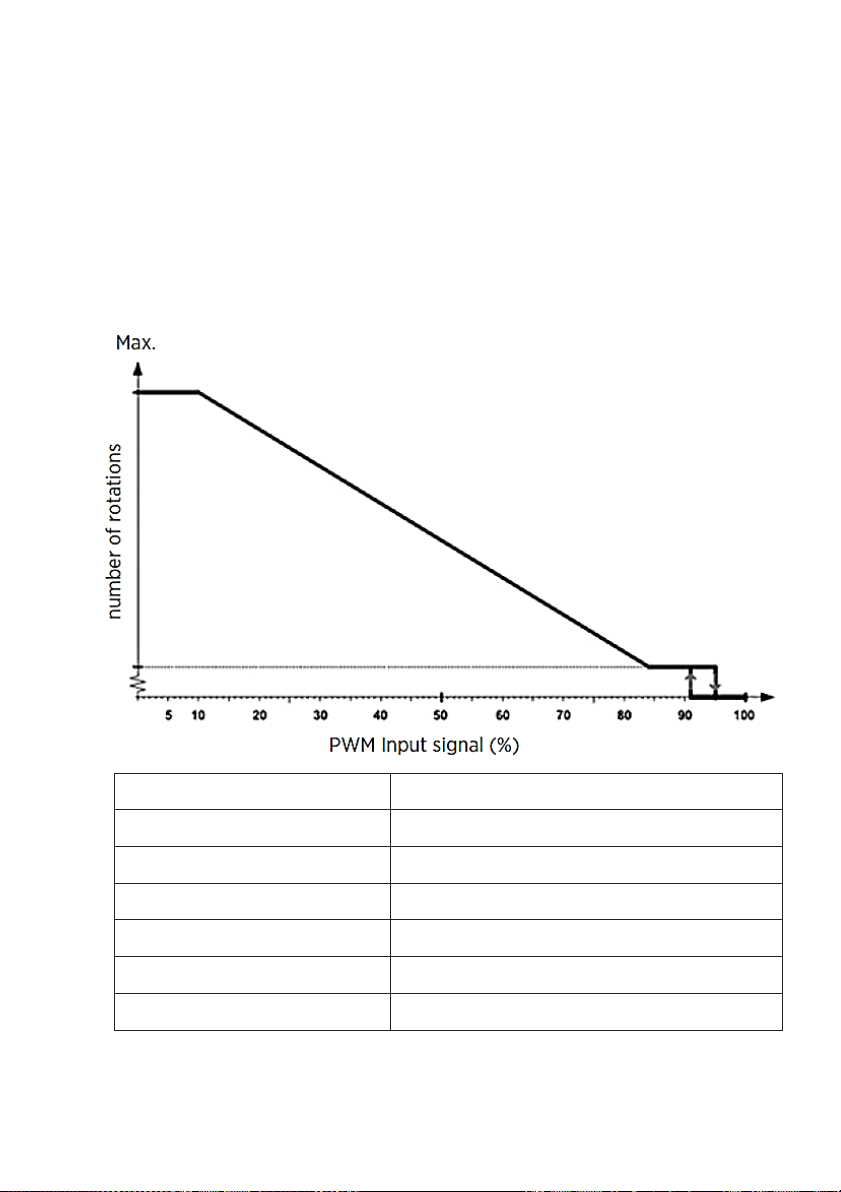
7.2 Heating characteristics P1
In the range from 0 to 10% of the PWM signal, the pump runs at maximum
speed for safety reasons.
(The prerequisite is that the pump is set to constant rotatioinal speed
adjustment III when selecting the operating level (chapter 6.3)).
In the event of a disturbance in the PWM adjustment or damage to the cable,
this ensures that the heat generated by the heat generator is transferred. This
is to prevent the system from overheating. In the range between 91 and 95%
of the PWM, the hysteresis prevents the pump from continually switching
when the PWM signal oscillates around the switch point.
PWM input signal (%) Pump status
PWM = 0 The pump switches to internal control
0 < PWM ≤ 10 Maximum rotational speed: Max.
10 < PWM ≤ 84 Variable speed: max. to min.
84 < PWM ≤ 91 Minimal rotational speed: Min.
91 < PWM ≤ 95 Hysteresis range: on/off
95 < PWM ≤ 100 Standby mode: off

18
7.3 Solar characteristics P2
In the range from 0 to 5% of the PWM, the pump stops for safety reasons. If
the PWM signal is switched off, e.g. due to a fault in the controller or an
interruption in the signal cable, the pump stops. This is to prevent overheating
of the solar system. In the range between 5 and 8% of the PWM, the
hysteresis prevents the pump from continually switching when the PWM
signal oscillates around the switch point.
(For the pump to run at maximum speed in the range of 98% to 100% of the
PWM, it must be set to constant rotational speed adjustment III when
selecting the operating level (chapter 7.3)).
PWM input signal (%) Pump status
PWM = 0 The pump stops
0 < PWM ≤ 5 Standby mode: off
5 < PWM ≤ 8 Hysteresis range: on/off
8 < PWM ≤ 15 Minimal rotational speed: Min.
15 < PWM ≤ 90 Variable speed: max. to min.
90 < PWM ≤ 98 Maximum rotational speed: Max.
98 < PWM ≤ 100 The pump switches to internal control

19
7.4 PWM feedback signal (power consumption)
By means of a PWM feedback signal, it is possible to send information about
the operating status of the pump to an external control. It contains
information about the actual power consumption and errors of the pump. The
output signal has a constant frequency of 75 Hz and is galvanically insulated
from the rest of the pump electronics. The table below shows which PWM%
values correspond to each operating statuses:

20
PWM input
signal (%)
QT *
(s)
Pump feedback DT *
(s)
Priority*
95 0 Standby (Stopp) 0 1
90 30 Error, pump rotor blocked 12 2
85 0-30 Alarm, stop: electronics
error 1-12 3
75 0 Warning 0 5
0-70 /
8m: 0-80W
(slope of 7/8 %PWM/W)
10m: 0-140W
(slope of 7/12 %PWM/W)
12m: 0-180W
(slope of 7/18 %PWM/W)
/ 6
The output
frequency 75Hz +/- 5%
QT* = (Qualification time) This value indicates how long the operating state
must be present for proper feedback to occur.
DT* = (Disqulification time) This value indicates the time after which the error
message is reset if the error no longer occurs.
Priority* = This number indicates the priority with which the operating status is
reported. The lower the number, the higher the priority.
This manual suits for next models
5
Table of contents
Other Stuart Turner Industrial Equipment manuals


