Stuart Turner MAINSBOOST iBOOST F200 Guide
Read this manual carefully before commencing installation.
This manual covers the following products:
iBOOST F200 CAT 5
Pt. No. 46677
iBOOST V200 CAT 5
Pt. No. 46713
Please note images are representative only and
may not portray your model
MAINSBOOST iBOOST
Installation, Operation & Maintenance
Instructions
Please leave this instruction booklet with the home owner as it
contains important warranty, maintenance and safety information

- 2 –
PRODUCT DESCRIPTION
iBOOST F200 CAT 5
Water pressure and flow booster set with integral water storage tank and electric
motor driven centrifugal pump complete with an automatic control system, consisting
of flow switch, pressure switch, pressure vessel and electronic control. The tank
design incorporates a weir type overflow to BS EN 1717, type AB giving isolation to fluid
category 5.
iBOOST V200 CAT 5
Water pressure and flow booster set with integral water storage tank and electric
motor driven centrifugal pump complete with an automatic variable speed control
system, consisting of pressure transducer and integral variable speed drive. The tank
design incorporates a weir type overflow to BS EN 1717, type AB giving isolation to fluid
category 5.
APPLICATION
The Mainsboost iBoost 200 CAT 5 is designed to meet the demand of pressurised
water systems where the existing mains water supply is insufficient. Inlet pressures
to the tank and ambient temperatures must not exceed the values given in the
technical specifications.
STORAGE
If this product is not to be installed immediately on receipt, ensure that it is stored in a
dry, frost and vibration free location in its original packaging.
CONTENTS Page
Checklist . . . . . . . . . . . . . . . . . . . . . . . . . . . . . . . . . . . . . . . . . . . . . . . . . . . . . . . . . . .5
Important Facts – read before commencing installation . . . . . . . . . . . . . . . . . . . . . .6
Location . . . . . . . . . . . . . . . . . . . . . . . . . . . . . . . . . . . . . . . . . . . . . . . . . . . . . . . . . . . .7
Key Features . . . . . . . . . . . . . . . . . . . . . . . . . . . . . . . . . . . . . . . . . . . . . . . . . . . . . . . .8
Installation & Pump Connections . . . . . . . . . . . . . . . . . . . . . . . . . . . . . . . . . . . . . . . .9
Electrical Installation . . . . . . . . . . . . . . . . . . . . . . . . . . . . . . . . . . . . . . . . . . . . . . . . . .13
Commissioning . . . . . . . . . . . . . . . . . . . . . . . . . . . . . . . . . . . . . . . . . . . . . . . . . . . . . .16
Maintenance . . . . . . . . . . . . . . . . . . . . . . . . . . . . . . . . . . . . . . . . . . . . . . . . . . . . . . . . .20
Technical Specification . . . . . . . . . . . . . . . . . . . . . . . . . . . . . . . . . . . . . . . . . . . . . . . .22
Trouble Shooting . . . . . . . . . . . . . . . . . . . . . . . . . . . . . . . . . . . . . . . . . . . . . . . . . . . . .24
Warranty Policy Terms and Conditions . . . . . . . . . . . . . . . . . . . . . . . . . . . . . . . . .26
- 27 –

- 3 –
WARNINGS:
This pump set must not be used for any other
application without the written consent of Stuart
Turner Limited.
This appliance can be used by children aged from
8 years and above and persons with reduced physical,
sensory or mental capabilities or lack of experience
and knowledge if they have been given supervision or
instruction concerning use of the appliance in a safe
way and understand the hazards involved.
Children shall not play with the appliance.
This product should not be used for the supply of
water to more than one dwelling (house, apartment,
flat).
Cleaning and user maintenance shall not be made by
children without supervision.
Maximum head (closed valve) 45 metres.
The motor casing can become very hot under normal
operating conditions. Care must be taken to ensure it
cannot be touched during operation.
The electrical installation must be carried out
in accordance with the current national electrical
regulations.
The electrical installation must be installed by a
qualified person.
F200: In the interests of electrical safety a 30 mA
residual current device (R.C.D. not supplied)
should be installed in the supply circuit. This may be
part of a consumer unit or a separate unit.
V200: RCD’s/ELCB’s are not recommended for use
with variable speed drives/motors. If an RCD is
mandatory use type B RCD’s.
For single phase sets with invertor motors
the earth leakage circuit breaker must trip out
when an earth fault currents with DC content
(pulsating DC) occur.

- 4 –
RCD’s suitable for use with variable speed
drives/motors are not suitable for personnel
protection.
Do not touch any electrical components for at
least 5 minutes after the unit has stopped to
allow any discharge to occur safely.
Before starting work on the electrical supply ensure
power supply is isolated.
DO NOT allow the supply cord to contact hot
surfaces, including the motor shell, pump body or
pipework. The cord should be safely routed and
secured by cable clips.
This appliance must be earthed via the supply cord,
which must be correctly connected to the earth
point located in the terminal box.
The supply cord and internal wiring within the
terminal box are routed and secured to ensure
compliance with the electrical standard
EN 60335–1. It is essential that prior to any
disturbance of this internal wiring, all cable routing
and securing details are carefully noted to ensure
re-assembly to the same factory pattern is always
maintained.
If the supply cord is to be changed or is damaged, it
must be replaced with a special cord assembly
available from Stuart Turner or one of their approved
repairers.
In order to avoid toppling over the appliance must
be placed on a smooth, level surface and the
retaining strap must be fitted.
Please read installation details carefully as they are intended to ensure this product
provides long, trouble free service. Failure to install the unit in accordance with the
installation instructions will lead to invalidation of the warranty.
- 5 –
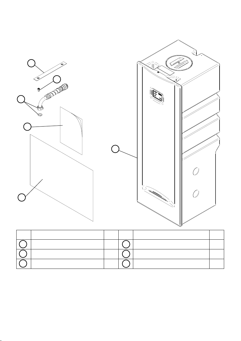
CHECKLIST
Note: Item B supplied loose – this will require fitting to the pump outlet. Tighten to
torque 4/5 Nm.
Your product may vary slightly from the picture above.
Item Description Qty Item Description Qty
iBoost 200 CAT 5 1 M6 screw 1
Hose & sealing washer 1 Instruction book 1
Retaining strap 1 Installation template 1
A
E
C
B
D
F
Fig. 1
IMPORTANT: With the appliance removed from
its packaging check for any damage prior to
installation. If any damage is found contact Stuart
Turner Ltd within 24 hours of receipt.
A
D
C
E
F
B

- 6 –
1 IMPORTANT FACTS: READ BEFORE COMMENCING PUMP INSTALLATION
A Water storage capacity.
1.11 The iBoost has a usable water volume of approximately 200 litres; the length
of time the iBoost delivers water will be dependent on the usage and refill
rates.
1.12 Ensure the pump is primed as described in the priming section before
starting, to avoid causing damage to the pump shaft seal. See Section 6 –
Commissioning.
B Water temperature
This unit is designed to pump cold water only which should not exceed the
following values:
1.13 The maximum allowable water temperature is 23 oC (see Section 7.13).
1.14 The minimum allowable water temperature is 4 oC.
C Pipework – General
1.15 Do not drill holes or put fastenings into the iBoost tank, this will cause
leakage.
1.16 System leaks: Ensure the system to be boosted is able to hold pressure and
is leak free before installing iBoost. Failure to do so will cause abnormal
operation and damage to the unit.
1.17 Secure pipework: Ensure pipework to and from pump is independently
supported & clipped to prevent forces being transferred to inlet and outlet
branches of pump. Do not secure pipework to the iBoost, this will cause
damage and possible leakage.
1.18 Flux: Solder joints must be completed and flux residues removed prior to
iBoost installation (flux damage will void any warranty).
1.19 Pipework design: Care should be taken in the design of pipework runs to
minimize the risk of air locks e.g. use drawn bends rather than 90obends.
1.20 DO NOT introduce solder flux to flexible hose, tank, pump or any parts
manufactured from plastic.
1.21 DO NOT allow contact with oil or cellulose based paints, paint thinners
or strippers, acid based descalents or aggressive cleaning agents.
1.22 DO NOT bend the flexible hose beyond 30o. It must be installed as
straight as possible.
1.23 DO NOT feed other header or gravity tanks with iBoost. It is
acceptable to feed toilet cisterns provided the toilet fill valve operates
correctly and is leak free.
D Plumbing Installation Regulations
1.24 The plumbing installation must comply with the current water and building
regulations.
1.25 The plumbing installation must be installed by a qualified person.
E Pressure vessel
1.26 The iBoost F200 Pressure vessel is charged at the factory see Section 7 –
Maintenance for details.
1.27 The iBoost V200 pressure vessel pre-charge must be set correctly during
installation, see section 6.12 for details.

- 7 –
2 LOCATION GENERAL
2.11 Access: For emergencies and maintenance the pump must be
easily accessible.
2.12 Protection: The iBoost must be located in a dry, frost free area. The
iBoost must not be installed in a loft space.
2.13 Ventilation: Ensure an adequate air flow to cool the iBoost.
Separate the iBoost from other appliances that generate heat. Do
not block the vent holes on the front panel.
2.14 Safety: Motor is not accessable in normal operating mode. Unit
must only be operated with the front cover in place.
2.15 Water retention: Site the iBoost in a location where in the unlikely
event of overflow, water leak, any spillage is contained or routed to
avoid electrics or areas sensitive to water damage.
The iBoost has a weir type overflow at the rear of the tank, in the
event of overflow, the water will drain from the weir area.
A minimum gap of 50 mm must be allowed at the rear of the tank to
allow any possible overflow water to exit the weir area. The weir
area must not be blocked or covered.
2.16 Supply inlet pressure: The water supply inlet pressure must be lower than
7 bar; lower supply inlet pressures will reduce the tank fill rate and reduce the
time the iBoost will run at higher flow rates before running out of stored water.
2.17 Ambient temperature: The iBoost must be sited in a location where the
ambient temperature does not exceed 30 oC (see Section 7.13 – Water
Quality).
2.18 Pipework: For optimum performance outlet pipework must be 22 mm pipe.
Pipework should only reduce to 15 mm when entering terminal fittings.
2.19 Static outlet pressure: The static outlet head must also be within the
maximum requirement of 15 metres (vertically above the appliance).
2.20 Noise: A flexible hose is supplied as standard which will minimise the
transmission of noise and vibration from the iBoost pump to the pipework
connected to the appliance outlet. However, care must be taken when
mounting the iBoost that any noise is not amplified through loose panels or
pipework.
2.21 Direction of flow: Ensure the water flow is in the direction of the arrow
marked on the flow switch reed clamp (vertically upwards).
2.22 Flexible hose: Only use the Stuart Turner hose supplied with the pump.
2.23 Isolating valves: Separate system isolating valves (non restrictive) must be
fitted to allow easy pump service. Isolating valves must be mounted where
specified to allow the system isolation and removal of the iBoost if needed.
See Section 4 for installation details.
2.24 Preferred iBoost location: The preferred iBoost location is on a smooth level
floor of sufficient strength to support the filled weight of the iBoost close to
the water source and a suitable overflow position (see Section 8 – Technical
Specification for filled weight).
The iBoost must not be installed in a loft space.
It must also be considered that the noise and vibration from the iBoost may
be transmitted through the structure the iBoost is sited on.
Ensure there is sufficient room above the iBoost to allow the removal and
servicing of the internal float valve if needed, typically 350 mm.

- 8 –
3 KEY FEATURES
iBoost F200 CAT 5
iBoost V200 CAT 5
Label
Part No & Serial No
Overflow
Outlet hose
Pressure vessel
Drain valve
Tank
Tank access cover
Mains water connection
User interface
User interface cable
Pump module
Pump module retaining
screws
Pump isolation valve
(behind pump)
Fig. 2
Retaining strap
Cover retaining
screw location
Label
Part No & Serial No
Overflow
Outlet hose
Pressure vessel
Drain valve
Tank
Tank access
cover
Mains water
connection
User interface
Pump module
Pump module retaining
screws
Pump isolation
valve (behind
pump)
Note: iBoost shown with
front cover removed
Fig. 3
Retaining strap
Cover retaining screw
location
Weir aperture
- 9 –
4 INSTALLATION & PUMP CONNECTIONS
4.11 Mains water connection to iBoost 200 CAT 5: The iBoost is to be
permanently connected to the mains water supply using rigid pipe or
suitably sized and rated flexible hose to comply with current building and
plumbing regulations.
The water tank fill valve has a G ½ male threaded fitting; a suitable 90oelbow
type fitting must be used. When tightening ensure the fill valve within the
tank is not rotated. If the valve is rotated it may not function correctly with
the risk of flooding.
Ensure there is a demountable joint in the pipe to allow the removal of the
iBoost if needed (see Fig. 8).
4.12 Water outlet pipework:
1. The pump has a G ¾ threaded connection to accept the supplied hose.
The hose is made water tight with a sealing washer on assembly, nip
tight to 4 to 5 Nm for water tight seal. (Do not overtighten). The supplied
hose must only be connected to 22 mm pipework.
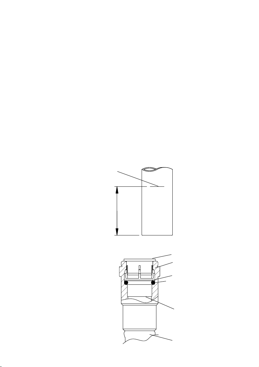
Ensure the pipe is free from all score marks and deformities in the area of
the insertion depth (Fig. 4) and cut the pipe square removing all burrs and
sharp edges to prevent damage to the sealing ‘O’-ring.
2. Prior to inserting the pipe into the fitting mark the insertion depth on the
wall of the pipe with a soft pencil at a distance of 33 mm from the end to
be inserted.
3. Check in the mouth of the fitting that the ‘O’-ring, nylon washer and collet
are in position.
Fig. 4
Pencil mark
Insert depth
33 mm
Pipe
Fig. 5
Collet
Body
Washer
‘O’-ring
Pipe stop
Hose

- 10 –
4. Push pipe firmly into fitting, until pencil mark is level with the top of the
collet and the pipe stop resistance is felt. Pull on the pipe to check it is
secure and correctly fitted.
5. To break the joint, push pipe firmly into fitting, hold collet down and
gently remove pipe. If the system has been fitted with water care should
be taken to isolate pump and towels used to absorb spilled water.
4.13 Connection to warning pipe: The overflow fitting is designed to use
G ¾ (21.5 mm OD) plastic waste pipe. Ensure there is a demountable joint in
the pipe to allow the removal of the iBoost if needed (see Fig. 8). The
warning pipe must be free to vent to atmosphere either via a tundish or a
dedicated external pipe.
4.14 The iBoost is intended to be either installed as a freestanding unit with its
back to a wall (minimum gap 50 mm) or into a 600 mm wide, 2 m high
cupboard. If installed into a 600 mm cupboard the floor and back panel will
need to be removed and the cupboard spaced forward to allow the 50 mm
clearance at the rear to allow for the weir overflow discharge. The carcass of
the cupboard will need to be screwed to the adjacent units and the wall for
support (also see section 2.15).
All the services are connected to the iBoost via a plumbing access window at
the back of the unit, the installation is conducted in 4 simple steps.
Prior to installation remove the screw on the top of the unit and pull the
corner of the front cover to remove it and retain them in a safe place.
Step 1
Position the paper installation template on the wall where the iBoost is to be
installed, ensuring the ‘floor level’ of the template is level and resting on the
surface the iBoost is to be mounted on (Fig. 6).
InstallationTemplate
140
100
480
320
600
100
Fig. 6
Mains water
supply
Non-pumped
water supply
Warning pipe
Floor
(see 2.24)
All dimensions in mm
Pumped water
supply
Tundish
External
overflow
Template
- 11 –
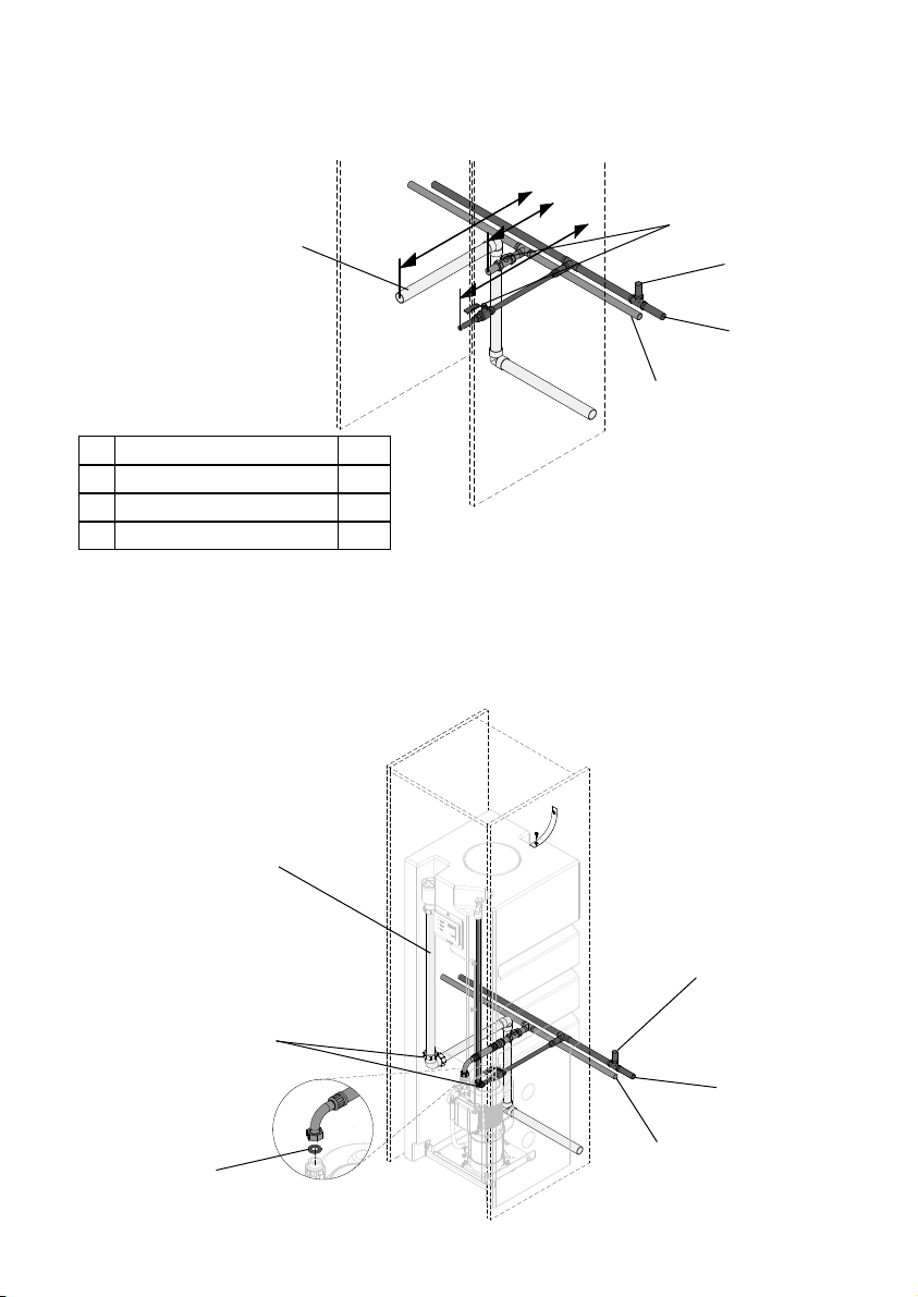
Step 2
Run the mains water, pumped water supply and overflow to the template
positions and make the pipe length as detailed in Fig 7.
Step 3
Slide the iBoost into position in front of the services leaving approximately
50 mm gap between the iBoost and the wall behind.
Connect the services using isolation valves and demountable fittings (push-fit
or compression) where shown in Fig. 8. The positioning of these fittings allow
the iBoost to be removed without cutting pipes or draining the system.
Fig. 8
Overflow
Non-pumped
water supply
Mains water
supply
Pumped water
supply
Demountable
fittings
Sealing washer
Fig. 7
Mains water
supply
Pumped water
supply
Overflow
Isolating valve
Non-pumped
water supply
A
B
C
Length of pipework from wall* mm
A Overflow 520
B Pumped water (iBoost outlet) 220
C Mains water supply 530 *Lengths are dependent on fittings used

- 12 –
Step 4
Fix the retaining strap to the top of the iBoost using the M6 screw provided.
The free end of the strap must be secured to suitable wall using a suitable
fastening system.
4.15 It is recommended that at least one drinking water tap is connected into the
un-pumped mains water supply (typically a kitchen sink), so the water supply
is maintained in the event of a failure of the pumped supply.
Fig. 9
Secure to wall using
suitable fastener (not
supplied)
Retaining strap
M6 screw

- 13 –
5 ELECTRICAL INSTALLATION EARTHING
5.11 Regulations: The electrical installation must be carried out in
accordance with the current national electrical regulations and
installed by a qualified person.
5.12 Safety – F200: In the interests of electrical safety a 30 mA residual
current device (R.C.D. not supplied) should be installed in the
supply circuit. This may be part of a consumer unit or a separate
unit.
Safety – V200: RCD’s/ELCB’s are not recommended for use with
variable speed drives/motors. If an RCD is mandatory use type B
RCD’s.
For single phase sets with invertor motors the earth leakage
circuit breaker must trip out when an earth fault currents with
DC content (pulsating DC) occur.
RCD’s suitable for use with variable speed drives/motors are
not suitable for personnel protection.
Do not touch any electrical components for at least 5 minutes
after the unit has stopped to allow any discharge to occur
safely.
5.13 Before starting work on the electrical supply ensure power supply is
isolated.
5.14 DO NOT allow the supply cord to contact hot surfaces, including the
motor shell, pump body or pipework. The cord should be safely
routed and secured by cable clips.
5.15 Adjacent pipes: Adjacent suction and delivery pipes should be fitted with
earthing clamps in accordance with current regulations (Fig. 10).
5.16 Earthing: This appliance must be earthed via the supply cord, which must be
correctly connected to the earth point located in the terminal box.
5.17 Pipework: Copper or metallic pipework must have supplementary earth
bonding where the continuity has been broken by flexible hoses or plastic
components.
5.18 Additional earthing: Certain installations may require additional earthing
arrangements such as equipotential bonding. Reference should be made to
the relevant regulations concerning this subject to ensure compliance.
5.19 Connections: The pump must be permanently connected to the fixed wiring
of the mains supply using the factory fitted supply cord, via a double pole
switched (with a minimum of 3 mm contact separation) fused spur off the ring
main and NOT connected to the boiler or the immersion heater circuits.
Diagram
of earth
continuity
connections
Fig. 10
- 14 –
5.20 The electrical connection must be made adjacent to (not behind) the iBoost
to allow disconnection of the electrical supply should the pump module need
to be removed for service or maintenance.
5.21 Wiring of connection unit:
WARNING: This appliance must be earthed.
The wires in the mains lead (supply cord) are coloured in accordance with the
following code:
Green and Yellow: Earth
Blue: Neutral
Brown: Live
As the colours of the wires in the mains lead of this appliance may not
correspond with the coloured markings identifying the terminals in your
connection unit proceed as follows:
The wire which is coloured green and yellow must be connected to the
terminal in the connection unit which is marked with the letter E or by the
earth symbol: or coloured green or green and yellow.
The wire which is coloured blue must be connected to the terminal which
is marked with the letter N or coloured black.
The wire which is coloured brown must be connected to the terminal
which is marked with the letter L or coloured red.
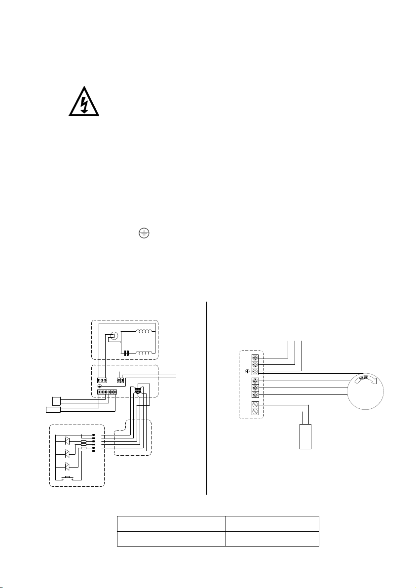
5.22 Wiring Diagrams:
Model Fuse Size (AMPS)
iBoost all models 10
5.23 Fuses: The following fuse size should be used:
MAIN WINDING
THERMOTRIP
CAPACITOR START WINDING
FLOWSWITCH
REED (S3)
BLACK
RED
RED
GREEN / YELLOW
BLUE
BROWN L
E
N230 VAC/1PH/50Hz
SUPPLY
NMNL
PRESSURE
SWITCH (S1)
S2 S3 S3 S2 S1S1
0V D1
D2 D3 SW0V
MOTOR
PCB
28480
D1
D2
D3
SW1
0V
0V
LED 1
LED 2
LED 3
SW 1
COMM 1
PIN 1
PIN 6
KEYPAD
28481
CABLE
20047
ORANGE
GREEN
RED
WHITE
BLACK
BLUE
R1
R2
R3
6 4 2
5 3 1
YELLOW
Fig. 11
iBoost F200 CAT 5
L
N
V
U
W
24V
Psi
230 VAC/1PH/50Hz
SUPPLY
GREEN / YELLOW
BLUE
BROWN
4-20mA
PRESSURE
TRANSDUCER
MOTOR
230VAC/3PH/50Hz
GREEN / YELLOW
BLUE
BLUE
BROWN
CONTROLLER
PCB
BROWN OR BLACK
BROWN OR BLACK
TO BE WIRED TO TURN
MOTOR IN CLOCKWISE
DIRECTION WHEN
VIEWING FAN END
LNE
Fig. 12
iBoost V200 CAT 5
- 15 –
5.24 Supply Cord Replacement:
The supply cord and internal wiring within the terminal box are
routed and secured to ensure compliance with the electrical
standard EN 60335–1. It is essential that prior to any disturbance
of this internal wiring, all cable routing and securing details are
carefully noted to ensure re-assembly to the same factory pattern
is always maintained.
If the supply cord is to be changed or is damaged, it must be replaced with a
special cord assembly available from Stuart Turner or one of their approved
repairers.
On disassembly note the cord retention and routing system. Re-assemble to
the same pattern.
For information on cable connection consult the wiring diagram and cable
gland fitting instructions.
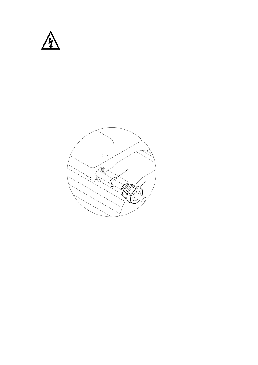
5.25 Cable Gland Fitting Instructions:
iBoost F200 CAT 5
To enable correct assembly of the cable gland the ‘O’-ring (Fig. 13 item 1)
must be placed over the cable before the clamping insert (Fig. 13 item 2)
can be tightened.
Note: Cable diameter range:- 9.2 mm to 11.9 mm.
iBoost V200 CAT 5
For information on cable gland fitting contact Stuart Turner Ltd.
5.26 Supply Cord Extension:
The pumps are fitted with a supply cord to the following specification:-
All models. . . . . . . . . . . . . . . . .HO7RN-F3 G 1.5 mm² – 10 Amp rated cable.
If the supply cord is to be extended, a cord of the same specification should
be used. Any connections or junction boxes used should be specifically
suited for the application and installed in accordance with the manufacturers
instructions.
Fig. 13
2
1
- 16 –
6 COMMISSIONING STARTING
iBoost F200 CAT 5
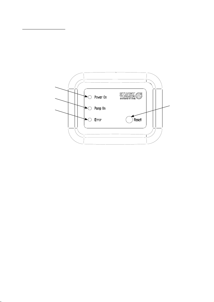
6.11 The iBoost is fitted with a user interface, this has the following indicator lights
A) Green – illuminated when the mains power is supplied to the iBoost
B) Orange– illuminated when the pump is running
C) Red – illuminated when the iBoost runs out of water and is in dry run
protection mode.
The user interface also has a ‘Reset’ button (D), this is only functional when
the red ‘Error’ light is illuminated.
A
B
C
Fig. 14
D
5

- 12 –
Cont ...
Step 4
Fix the retaining strap to the top of the iBoost using the M6 screw provided.
The free end of the strap must be secured to suitable wall using a suitable
fastening system.
4.15 It is recommended that at least one drinking water tap is connected into the
un-pumped mains water supply (typically a kitchen sink), so the water supply
is maintained in the event of a failure of the pumped supply.
Fig. 9
Secure to wall using
suitable fastener (not
supplied)
Retaining strap
M6 screw
- 17 –
iBoost V200 CAT 5
6.12 The iBoost V200 control panel is seen mounted directly on the front of the
pump motor and has to be set up while the front cover is removed.
a) On switching on the power the display screen will light up showing two
figures, left hand being the system pressure and the right being the set
pressure, at this stage they will both be “0.0” bar. Please note the unit is
factory set to 3 bar.
b) Open a tap and then press “RUN” to start the pump.
c) At any time press “STOP” to stop the pump.
d) Use the “” and ““ buttons to increase or decrease to the desired
operating pressure of the unit (right screen) and the unit will adjust itself
to match as can be seen on the left screen.
e) Now open another tap the unit will sense the increase in demand and
increase its performance to match demand accordingly.
f) When no flow is detected, the unit will slow the pump to a standby mode.
g) Once the iBoost V200 target pressure has been set the pressure vessel
pre-charge must be adjusted accordingly to ensure correct function of
the unit, see section 7.11 for instruction on how to set the pre-charge. This
must be completed both on first installation and checked every 12 months.
Note: The maximum pressure this unit can generate is 4.5 bar. Do not set the
pressure required above 4.0 bar.
Fig. 15
23
6
78
9
10
45
1

- 18 –
6.13 The supply of water from the storage tank can be isolated from the pump by
use of the isolation valve behind the pump.
6.14 System Flushing
The pipework system should be flushed out prior to the iBoost
being connected to ensure any contaminants/chemical
residues and foreign bodies are removed from elsewhere in the
system.
6.15 Water Supply: Always ensure that water supply is adequate to meet the
demand. Ensure the pump chamber is full of water before starting the
pump. Failure to do this could result in seal damage. To ensure dry running
does not occur the pump must be primed as described in priming section
below. Do not run pump dry.
No Name or Function Comment
1Current system pressure
display Unit is bar.
2 Power indicator Will light up when the power is on.
3 Pump indicator
If the motor speed is being controlled up or down the indicator flashes
quickly.
If the motor is at constant speed showing lack of water, it flashes
slowly. When pressure is reached and no demand the indicator stays
on.
4Network connection
indicator
Indicator lights up when controller is connected to a network (not
applicable for this product).
5 Dry run protection See section 9.12.
6 Set pressure display Displays current pressure value in bar.
The factory default setting is 3 bar.
7 Decrease Press ths button to decrease in 0.1 bar steps.
8 Increase Press ths button to increase in 0.1 bar steps.
9 STOP Press to stop the pump manually (or to exit Dry run protection).
10 RUN Press to start the pump manually (or to exit Dry run protection).
Fig. 16
ON OFF

- 19 –
6.16 Priming:
Never operate pump with inlet and/or outlet isolating valves in the
closed position. Damage will occur!
The tank must be filled with water before starting the pump.
(a) Turn on the service valves nearest the iBoost and allow the air to vent
from the system.
(b) Turn on the iBoost and allow the pump to build up pressure purging the
air from the system..
(c) Open all the service valves (including flushing WCs) in turn to fully purge
the air from the system.
6.17 Starting:
a) Ensure all outlets are closed, turn power supply ‘on’ – pump will start,
pressurise the system then stop.
b) Open and close all outlets in turn associated with the pump, (including
w/c systems) allowing water to flow from each outlet until all air is
purged. As each outlet is opened and closed, the pump will start and stop
respectively.
Note: After closing the outlet there will be a small time delay before the
pump stops, which is normal.
c) Any tap or control valve within the system when opened and closed will
now turn the iBoost on/off, there will be a delayed start due to the water
stored in the pressure vessel. Providing this is the case the system is now
operating correctly.
d) Carefully check pump and pipework for leaks whilst pump running and
stationary before leaving the installation unattended.
6.18 For Further Technical Support: Phone the Stuart Turner TechAssist team
on +44 (0) 800 31 969 80. Our staff are trained to help and advise you over
the phone.
- 20 –
7 MAINTENANCE
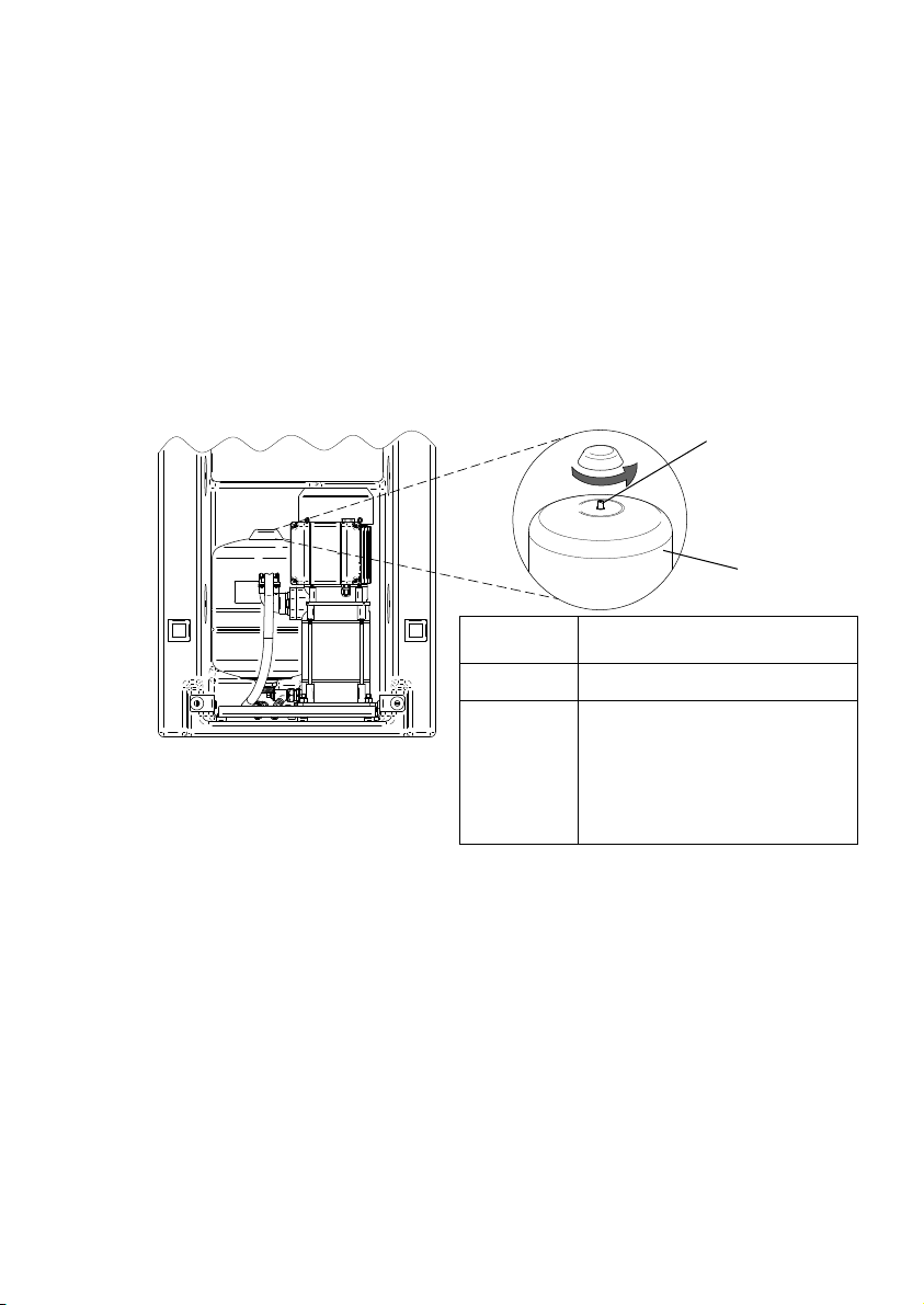
7.11 Pressure vessel: The pressure vessel should be checked once every
12 months to have its pre-charge checked or replenished, this should be
carried out as follows:-
a) Isolate pump electrically.
b) Remove the front cover.
c) Isolate the water supply by closing the appropriate isolating valves.
d) Release system water pressure by opening an outlet on the system.
e) Check pre-charge at Schrader valve (Fig. 17) using a tyre pressure gauge.
f) Replenish pre-charge by injecting air into the vessel via the Schrader valve
using a car or bicycle pump (Fig. 17).
g) Close all system outlets, open inlet and outlet isolating valves.
h) After maintenance is completed refer to Section 6 – Commissioning for
instructions on re-starting pump.
7.12 Water scale: In areas of hard water, scale can cause the mechanical pump seal
to stick if left without use for long periods. The pump must be run for at least
5 minutes every four weeks to “exercise” all working parts. See Section 8 –
Technical Specification for note on water temperature.
7.13 Water quality: The iBoost has been manufactured to the highest standard
from WRAS approved materials.
As with any stored volume of water; in order to ensure that the water remains
fit for use the water temperature needs to remain below 20 oC. The
quality of stored water will deteriorate with time and temperature. Bacterial
growth is dependent on the water temperature, growth rates will be higher
when the conditions are warm.
If the water remains unused for long periods of time, the tank should be
drained and flushed through. The tank should be cleaned on an annual basis
to protect against bacterial growth. The system must be maintained in line
with current Health & Safety regulations.
Fig. 17
Schrader valve
Pressure
vessel
Model Pre-charge
bar (psi)
iBoost F200 2.5 (36.2)
iBoost V200 The pressure vessel pre-charge
must be set to 90% of the
pump set pressure. I.e. If pump
pressure is set to 3 bar, then the
pre-charge value should be 3 x
0.9 = 2.7 bar (39 psi).
Cont ...
Other manuals for MAINSBOOST iBOOST F200
1
This manual suits for next models
3
Table of contents
Other Stuart Turner Industrial Equipment manuals


