Stuart Turner Monsoon Extra S1.4 bar User manual

INSTALLATION INSTRUCTIONS
SERVICE KIT - MONSOON EXTRA S1.4 bar SINGLE Part No. 28454
- MONSOON EXTRA U1.4 bar SINGLE Part No. 28455
Fig. 1
23 Capacitor
(not shown)
25 Adhesive
foam pad
(not shown)
5 Rotary seal
4 Seal counterface
All Models - see Sections 1 & 5
1 Thrower washer
3 ‘O’-ring
(ID 101.4 mm) 6 Plastic
spacer
7 Stainless washer
7
8 M8 locknut
9 ‘O’-ring
(ID 8 mm)
2 ‘O’-ring
(ID 6.07 mm)
Additional Parts
Fig. 2
11 Reed switch tie
wrap
24 Reed switch
14 ‘O’-ring
(ID 29.1 mm)
22 Non-return valve
assembly
19 Pressure switch
18 Pressure
vessel (0.6 litre)
U1.4 only - see Sections 2, 3 & 4
10 or 16
13 Grub screws
(M4 x 4 mm)
15 ‘O’-ring
(ID 13.6 mm)
17 Rubber washer
(OD 18 mm)
20 1/8 seal
OR
21 ‘O’-ring
(ID 10.1 mm)
S1.4 only - see Sections 2 & 4
10 Fibre washer
(OD 38 mm)
OR
16 ‘O’-ring (ID 35.1 mm)
11 Reed switch
tie wrap
24 Reed switch
Fig. 3
10 or 16
27 Screws
(M6 x 35 mm)
28 Screws
(M6 x 16 mm)
26 Screws
(3.5 x 12 mm)
29 PCB (not shown)

- 2 -
Cont ...
• COMPLETE KIT CONTENTS
This kit contains parts for a range of different pump types - please ensure you correctly identify
the relevant parts for the pump being serviced before commencing. Also refer to the relevant
section for detailed instructions for the correct installation of the parts.
Fitting of incorrectly identified parts could lead to pump failure. If in doubt
contact PumpAssist on +44 (0) 800 31 969 80.
ITEM QTY ITEM QTY
1 Thrower Washer 1 16 ‘O’-Ring (ID 35.1 mm) 3
2 ‘O’-Ring (ID 6.07 mm) 2 17 Rubber Washer (OD 18 mm) 1
3 ‘O’-Ring (ID 101.4 mm) 1 18 Pressure Vessel (0.6 litre) 1
4 Seal Counterface 1 19 Pressure Switch 1
5 Rotary Seal Assembly 1 20 1/8 Seal 1
6 Plastic Spacer 1 21 ‘O’-Ring (ID 10.1 mm) 1
7 Stainless Washer 2 22 Non-Return Valve Assembly 1
8 M8 Locknut 1 23 Capacitor 1
9 ‘O’-Ring (ID 8 mm) 1 24 Reed Switch 1
10 Fibre Washer (OD 38 mm) 3 25 Adhesive Foam Pad 1
11 Reed Switch Tie Wrap 1 26 Screws (3.5 x 12 mm) 4
12 Applicator Tool (not shown) 1 27 Screws (M6 x 35 mm) 2
13 Grub Screws (M4 x 4 mm) 3 28 Screws (M6 x 16 mm) 4
14 ‘O’-Ring (ID 29.1 mm) 1 29 PCB 1
15 ‘O’-Ring (ID 13.6 mm) 1
Check to see that you have all the above items and that they are not damaged. If any damage is
found contact Stuart Turner Ltd within 24 hours of receipt.
• PUMP PREPARATION
To prepare the pump to accept the service kit parts, each pump part must be removed noting
its exact position and sequence (Figs. 1, 2 & 3).
Now clean all the individual parts. Before fitting the new service kit parts, the pump and seal
type must be identified.
• CONTENTS PAGE
Section 1 Mechanical seal replacement .................................. 3
Section 2 Non-return valve/pressure vessel replacement ..................... 4
Section 3 Pressure switch replacement................................... 6
Section 4 Reed switch replacement ..................................... 8
Section 5 Capacitor replacement ....................................... 11
Section 6 Printed circuit board replacement ............................... 13

- 3 -
Cont ...
A Seal seat complete with rubber cup washer.
B Rotary seal assembly.
C Spacer.
D Stainless steel washer.
• MAINTENANCE AND CARE UPON ASSEMBLY
To allow ease of assembly along with correct functioning of the pump, the following points on
assembly are necessary.
• All pump parts must be free from debris and assembled correctly.
• The seal must always be replaced as a complete unit using the seal applicator tool as
provided.
• The seal faces must not be handled or damaged.
To assemble the seal correctly, the shaft must be clean and the following steps carried out.
1 Use side 1 of the applicator tool to push the seal seat (item A) firmly into the housing
ensuring it is located flat against back of housing.
2 Now use side 2 of the applicator tool to push the rotary section of the seal assembly
(item B) onto the motor shaft until it is flat against the seal seat (Fig. 5). The shaft
may be lubricated with clean water to assist assembly.
Assemble the spring and location plate onto the shaft so as to complete the seal
bellows assembly (Fig. 6).
3 The spacer (item C) and washer (item D) can then be placed on the shaft and whole
assembly located into position by screwing the impeller to its stop. The impeller
locknut should then be secured (Fig. 7).
• INITIAL OPERATING INSTRUCTIONS
• Do not run pump dry. Allow the water to be pumped to enter the pump body thus ensuring
the seal is lubricated before switching the pump on. Failure to do this will damage the seal.
• Carefully check pump and pipework for leaks whilst pump running and stationary before
leaving the installation unattended.
SECTION 1 - MECHANICAL SEAL REPLACEMENT
The parts required to replace the seal are:
ITEM QTY ITEM QTY
1 Thrower Washer 1 7 Stainless Washer 2
2 ‘O’-Ring (ID 6.07 mm) 2 8 M8 Locknut 1
3 ‘O’-Ring (ID 101.4 mm) 1 9 ‘O’-Ring (ID 8 mm) 1
4 Seal Counterface 1 12 Applicator Tool (not shown) 1
5 Rotary Seal Assembly 1 27 Screws (M6 x 35 mm) 2
6 Plastic Spacer 1 28 Screws (M6 x 16 mm) 4
• SEAL IDENTIFICATION
For certain pump variants your seal arrangements may be different from that supplied within the
service kit.
The seal as supplied is an alternative and is shown in order of assembly in Fig 4.
Fig. 4 A B C D
Fig. 5 Fig. 6
Fig. 7
Side 2 Side 1
Applicator Tool (Item 12)

- 4 -
Cont ...
SECTION 2 - NON-RETURN VALVE/PRESSURE VESSEL
REPLACEMENT
The parts required to replace the non-return valve and pressure vessel are:
ITEM QTY ITEM QTY
10 Fibre Washer (OD 38 mm) 1 16 ‘O’-Ring (ID 35.1 mm) 1
13 Grub Screws (M4 x 4 mm) 3 17 Rubber Washer (OD 18 mm) 1
14 ‘O’-Ring (ID 29.1 mm) 1 18 Pressure Vessel (0.6 litre) 1
15 ‘O’-Ring (ID 13.6 mm) 1 22 NRV Body Assembly 1
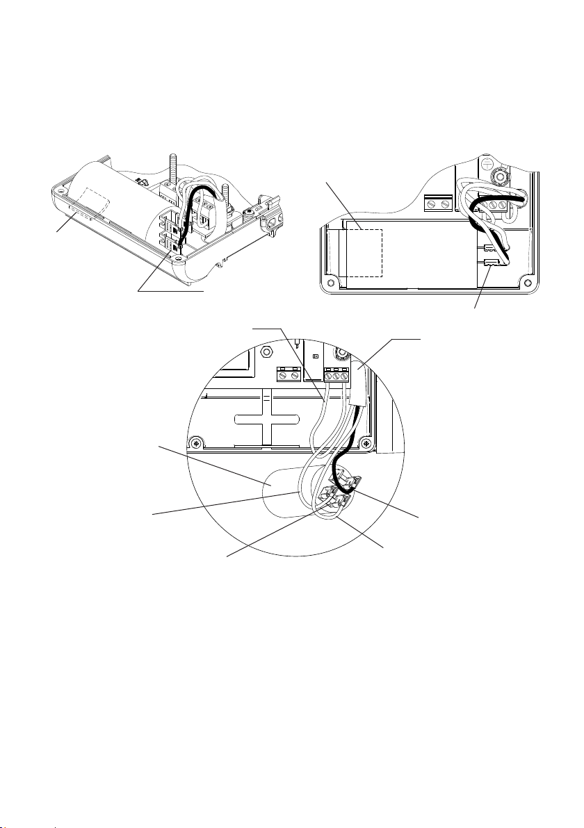
• DISASSEMBLY
Remove the following parts in the order shown:
1. Reed switch and tie wrap
2. Pressure vessel and ‘O’-ring (item 15)
3. 3 Grub screws (item 13) - 2 mm allen key required.
The flow switch assembly can now be removed from the NRV body being careful not to place
stress on the pressure switch cable. Note position of ‘O’-ring (item 14).
The NRV body assembly (item 22) can now be unscrewed from the pump head, noting the
position of ‘O’-ring (item 10 or 16).
Clean all parts that are to be re-used.
Damaged components must be replaced.
Contact Stuart Turner Ltd for replacements not supplied with kit.
Fig. 8
18
Reed Switch Tie Wrap
Flow Switch Assembly
Reed
Switch
13
10 or 16
22
14
Pressure Switch
15
17

- 5 -
Cont ...
• ASSEMBLY
Assembly is the reverse of the disassembly method.
Pressure vessel to be hand tightened.
Grub screws torque setting - 2.2 Nm
• PRESSURE VESSEL REPLACEMENT/CHARGE
Should ever the need arise for the vessel (item 18) to be replaced or have its air charge checked
or replenished, it should be carried out as follow:-
a) Isolate pump electrically.
b) Isolate hot and cold water supplies via the integral pump isolating valve
located in the flexible hoses.
c) Release system water pressure by opening a system outlet (tap).
d) Check air charge at Schrader valve using a tyre pressure gauge. The pressure should be set
at 0.9 bar (13 psi).
e) Replenish air charge if required by injecting air into the vessel via the Schrader valve using a
car or bicycle pump, ensuring a system outlet valve (tap) remains open during this procedure
to allow the vessel to exhaust any excess water.
f) Close all system taps, open hot and cold inlet pump isolating valves, turn on electrical power.
g) After maintenance is completed prime pump before re-starting.
• INITIAL OPERATING INSTRUCTIONS
• Do not run pump dry. Allow the water to be pumped to enter the pump body thus ensuring
the seal is lubricated before switching the pump on. Failure to do this will damage the seal.
• Carefully check pump and pipework for leaks whilst pump running and stationary before
leaving the installation unattended.

- 6 -
Cont ...
SECTION 3 - PRESSURE SWITCH REPLACEMENT
The parts required to replace the pressure switch are:
ITEM QTY ITEM QTY
19 Pressure Switch 1 21 ‘O’-Ring (ID 10.1 mm) 1
20 1/8 Seal 1
• DISASSEMBLY
• Isolate electrical supply before fitting.
• The supply cord and internal wiring within the terminal box are routed
and secured to ensure compliance with the electrical standard
EN 60335-1. It is essential that prior to any disturbance of this internal
wiring, all cable routing and securing details are carefully noted to
ensure re-assembly to the same factory pattern is always maintained.
To prepare the pump to accept the pressure switch, isolate and drain down the water. It may
be easier at this stage to remove the pump completely from its location.
Now disconnect the electrical connections from the pressure switch to the P.C.B.
The pressure switch cable restraint/sealing system will vary across model types.
Note the cable route, clamping and sealing method to enable re-assembly to same pattern
and proceed as follows:
The pump uses a rubber grommet for sealing and a cable strap for restraint. Release
cable strap and gently slide cable out through sealing grommet, to avoid damage to
enable re-use.
Damaged components must be replaced. Contact Stuart Turner for
replacements not supplied with kit.
Using a suitable open ended spanner (apply to brass switch part only), rotate the pressure
switch anticlockwise.
• MAINTENANCE AND CARE UPON ASSEMBLY
Depending on the age of your pump it may have a sealing washer (item 20) or ‘O’-ring (item 21)
always replace like for like.
Ensure the sealing faces for the pressure switch are clean before using the replacement sealing
washer.
Now tighten the pressure switch to 7 Nm torque.
Wiring of the switch can now be completed.
The strain relief bush, as supplied will suit the new switch and must be fitted.
2
1
Fig. 9
- 7 -
Cont ...
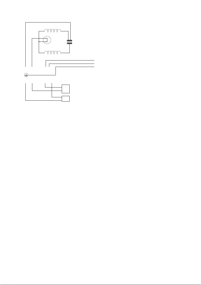
• WIRING DIAGRAM
• INITIAL OPERATING INSTRUCTIONS
1. Turn on water supply, prime and vent the pump via the vent plug. Unscrew slowly until
liquid emerges, then re-tighten.
Note: DO NOT RUN PUMP DRY.
2. Turn power supply to pump ‘on’ - pump will start, pressurise the system then stop.
3. Open and close all outlets in turn associated with the pump, (including w/c systems)
allowing water to flow from each outlet until all air is purged. As each outlet is opened
and closed, the pump will stop and start respectively.
Note: After closing the outlet there will be a small delay time before the pump stops, which
is normal.
4. Any tap or control valve within the system when opened and closed will now turn the pump
on/off. Providing this is the case the system is now operating correctly.
5. Carefully check pump and pipework for leaks whilst pump running and stationary before
leaving the installation unattended.
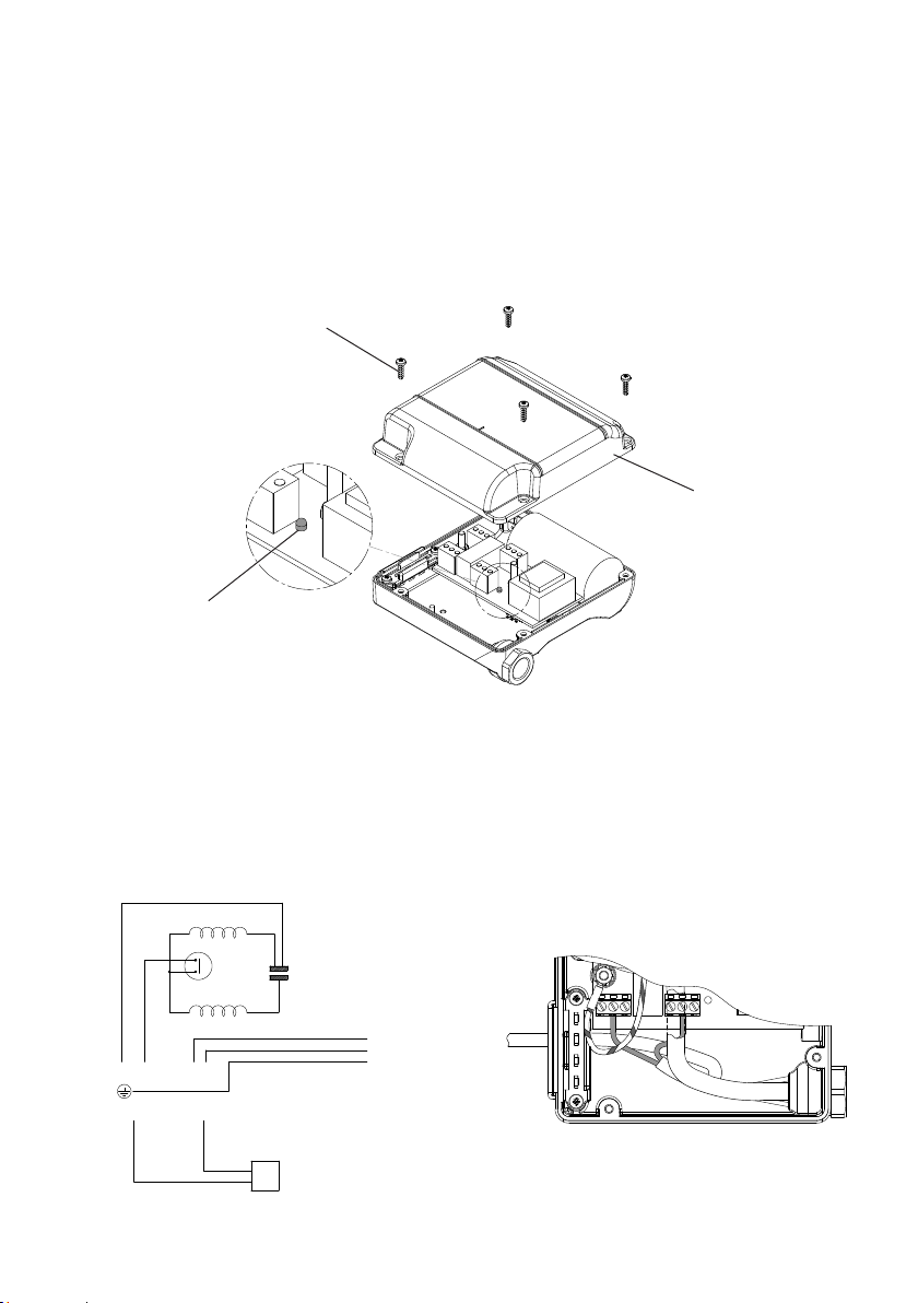
Fig. 10
MAIN WINDING
THERMOTRIP CAPACITOR
START WINDING
FLOWSWITCH
REED (S3)
LINK WIRE (BLUE)
BROWN
BLACK
GREEN / YELLOW
BLUE
BROWN L
E
N
230 VAC/1PH/50Hz
SUPPLY
BLUE
NMNL
S3 S3 S1
S1
PRESSURE
SWITCH (S1)

- 8 -
Cont ...
SECTION 4 - REED SWITCH REPLACEMENT
The parts required to replace the reed switch are:
ITEM QTY ITEM QTY
11 Reed Switch Tie Wrap 1 26 Screws (3.5 x 12 mm) 4
24 Reed Switch 1
• WIRING DIAGRAMS
Fig. Pump UK Eire
11 Monsoon Extra S1.4 bar Single ü ü
12 Monsoon Extra U1.4 bar Single ü ü
CAPACITOR
FLOWSWITCH
REED (S2)
LINK WIRE
BROWN
BLACK
GREEN / YELLOW
BLUE
BROWN L
S2 S2
E
N
230 VAC/1PH/50Hz
SUPPLY
BLUE
NMNL
FLOWSWITCH
REED (S2)
MOTOR
Fig. 11
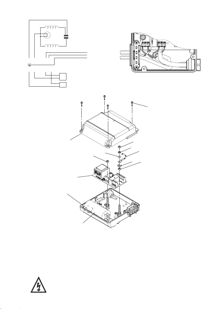
CAPACITOR
FLOWSWITCH
REED (S3)
LINK WIRE (BLUE)
BROWN
BLACK
GREEN / YELLOW
BLUE
BROWN L
S3 S3
E
N
230 VAC/1PH/50Hz
SUPPLY
BLUE
NMNL
S1 S1
PRESSURE
SWITCH (S1)
PRESSURE
SWITCH (S1)
FLOWSWITCH
REED (S3)
MOTOR
Fig. 12
Cable clamp & screws
- 9 -
Cont ...
• DISASSEMBLY
• Isolate electrical supply before fitting replacement part.
• Replacing the reed switch components should only be carried out by a
competent person.
• The supply cord and internal wiring within the terminal box are routed
and secured to ensure compliance with the electrical standard
EN 60335-1. It is essential that prior to any disturbance of this internal
wiring, all cable routing and securing details are carefully noted to
ensure reassembly to the same factory pattern is always maintained.
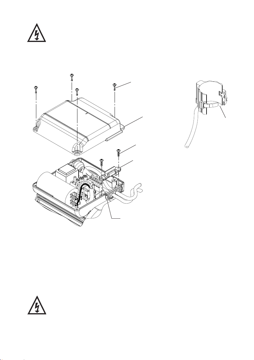
• Remove four screws and carefully remove terminal box lid (item 26).
• Note the cable routing within the terminal box (Figs. 11 or 12).
• Identify, disconnect and remove the reed switch wiring from the terminal block (Figs. 11 or
12).
• IMPORTANT – take note of the cable clamp orientation before removal, as reassembly in
the original factory orientation is essential. Remove two screws and cable clamp, this
allows any reed or pressure switch cables to be removed from the terminal box (Fig. 13).
• Remove the reed switch cable from the terminal box by gently sliding the cable out
through the grommet, ensuring no damage to the grommet sealing area (Figs. 11 or 12).
• Remove the existing reed switch by cutting the securing tie wrap and pulling away from
the body Fig. 14.
Damaged components must be replaced. Contact Stuart Turner for advice
on replacements not supplied with kit.
LN
MN
Fig. 13
26
Cable clamp screws
Cable clamp
Cable Grommet
Terminal box lid
Fig. 14
Cut tie
wrap
- 10 -
Cont ...
• REASSEMBLY
Reassembly is the reverse of the disassembly instructions with the new replacement parts
fitted as required.
Secure cable clamp screws and terminal box lid, to a torque of 0.8 Nm.
Note: For correct operation of the flow switch, the reed must be secured to the body as
detailed below.
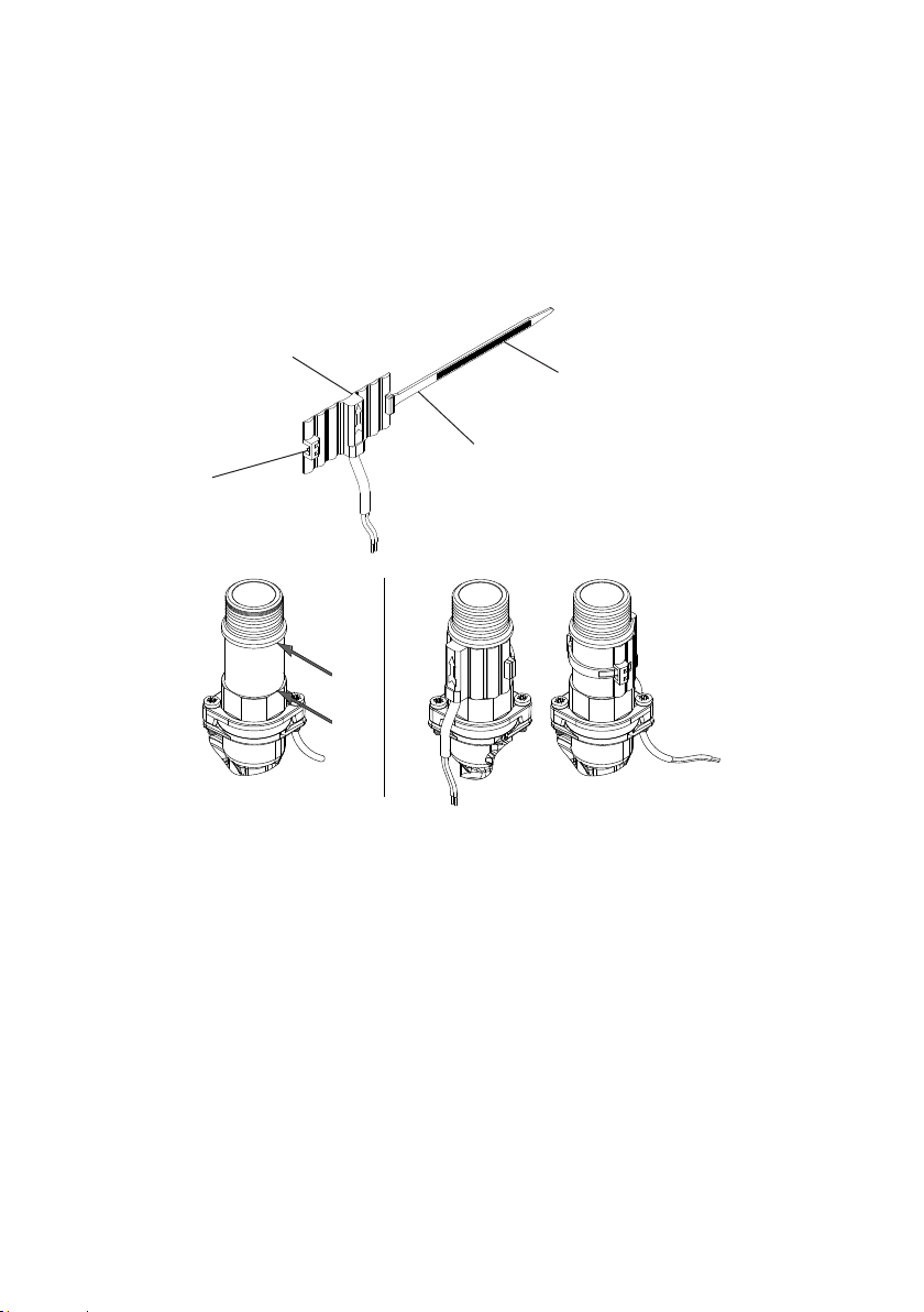
Firstly feed the tie wrap through the retainer on the reed switch, ensuring that the tie wrap
serrations are facing outward (Fig 15).
Now locate the reed switch within the body groove as highlighted X-X (Fig. 16), and feed
the tie wrap through the second catch.
The tie wrap can now be pulled tight to secure the reed and the excess cut to length (Fig. 17).
• INITIAL OPERATING INSTRUCTIONS
• Consult instruction manual for commissioning instructions.
• Do not run pump dry. Allow the water to be pumped to enter the pump body thus ensuring
the seal is lubricated before switching the pump on. Failure to do this will damage the seal.
• Carefully check pump and pipework for leaks whilst pump running and stationary before
leaving the installation unattended.
Fig. 15
24
Catch
Serrations
11
X
X
Fig. 16 Fig. 17
- 11 -
Cont ...
SECTION 5 - CAPACITOR REPLACEMENT
The parts required to replace the capacitor are:
ITEM QTY ITEM QTY
23 Capacitor 1 26 Screws (3.5 x 12 mm) 4
25 Adhesive Foam Pad 1
• DISASSEMBLY
• Isolate electrical supply before fitting replacement part.
• Replacing the capacitor, should only be carried out by a competent
person.
• The supply cord and internal wiring within the terminal box are routed
and secured to ensure compliance with the electrical standard
EN 60335-1. It is essential that prior to any disturbance of this internal
wiring, all cable routing and securing details are carefully noted to
ensure reassembly to the same factory pattern is always maintained.
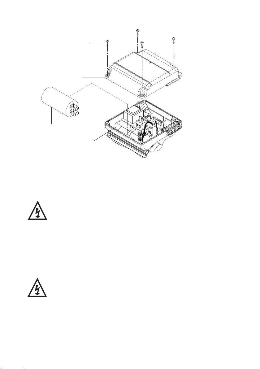
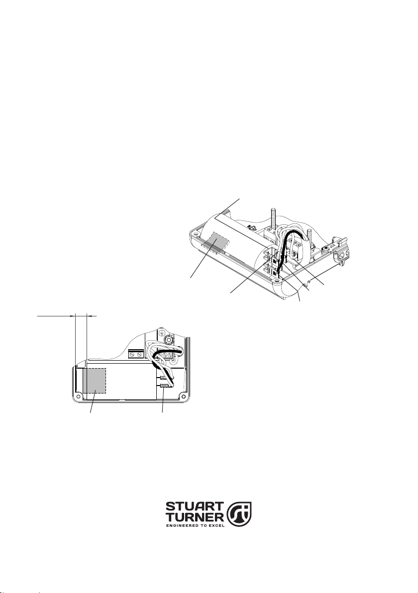
Reference Fig 18:
• Remove 4 screws (item 26), and carefully remove terminal box lid.
• IMPORTANT: Take note of capacitor wiring connection and colours before removal.
Disconnect and remove capacitor (item 23) and foam securing pad (item 25), make note of
pad fitted position.
Damaged components must be replaced. Contact Stuart Turner for
advice on replacements not supplied with kit.
LN
MN
23
25
26
Terminal box lid
Fig. 18
- 12 -
Cont ...
• REASSEMBLY
Reassembly is the reverse of the disassembly instructions, with new replacement parts fitted
as required.
Note: For correct installation the capacitor must be connected, secured and positioned as
detailed (Figs. 19, 20 & 21).
Secure terminal box lid screws to a torque of 0.8 Nm (item 26).
IMPORTANT NOTE: For correct pump rotation, ensure both blue wires are connected to the
linked capacitor terminals as shown.
• INITIAL OPERATING INSTRUCTIONS
• Consult instruction manual for commissiong instructions.
• Do not run pump dry. Allow the water to be pumped to enter the pump body thus ensuring
the seal is lubricated before switching the pump on. Failure to do this will damage the
seal.
• Carefully check pump and pipework for leaks whilst pump running and stationary before
leaving the installation unattended.
N
L
M
N
N
A
M
NL
25
Receptacles upright
Receptacles upright
Fig. 19 Fig. 20
Fig. 21
25
Brown wire from motor
connect to ‘M’ terminal Protective supplementary
insulation surrounding
motor flying wires
Black wire from motor
Blue wire from motor
Linked terminal
Link wire blue connect
to ‘N’ terminal
23

- 13 -
Cont ...
SECTION 6 - PRINTED CIRCUIT BOARD REPLACEMENT
The parts required to replace the printed circuit board are:
ITEM QTY ITEM QTY
25 Adhesive Foam Pad 1 29 Printed Circuit Board 1
26 Screws, Self Tapping (3.5 x 12 mm) 4
Note: - When fitted this printed circuit board will detect the following fault conditions:
• Dry running caused by water starvation to the pump.
If the above fault condition occurs, then the pump will stop.
The fault should therefore be rectified before restarting the pump.
Check that there is sufficient water supply to the pump and also ensure that all outlets are
closed.
• Protective Logic Sequence
If water starvation occurs and the power supply to the pump remains uninterrupted, the pump
controller will perform the following protective sequence.
1) If the pump detects water starvation, it will stop operation after a 1 minute period.
2) The pump will remain in the off condition for a period of 5 minutes.
3) The pump will then re-start and if the water starvation condition remains present, the pump
will then stop operation after a 1 minute period.
4) The pump will remain in the off condition for a period of 5 minutes.
5) The pump will then re-start and if the water starvation condition remains present, the pump
will then stop operation after a 1 minute period.
6) The pump will remain in the off condition for a period of 5 minutes.
7) The pump will then re-start and if the water starvation condition remains present, the pump
will then stop operation after a 1 minute period.
8) After three consecutive resets are performed the pump will remain in the off condition
indefinitely.
9) To restart the pump, the power supply should be first isolated for a period of at least 10
seconds before switching on again.
If the pump fails to operate normally after three attempts to re-start, then please consult Stuart
Turner PumpAssist +44 (0) 800 31 969 80.
• Fault Finding
The PCB is also fitted with a “power on” indicator light. This will remain illuminated when
mains power is supplied to the board.
The indicator light is located on the PCB within the terminal box.
This operation should only be carried out by a competent person
- 14 -
Cont ...
To view the light the following procedure must be followed:-
• Isolate the mains electrical power supply from the pump.
• Remove the four screws (item 26) retaining the terminal box lid (Fig. 22).
• Lift the terminal box lid off.
• IMPORTANT – Ensure there is no contact with any of the internal parts of the terminal box.
• Briefly reconnect the mains power supply to the pump – the indicator light should illuminate if
the pump has been correctly wired.
• Isolate the mains electrical power supply from the pump.
• Re fit the terminal box lid ensuring no cables are trapped.
• Re fit the four terminal box lid retaining screws, tighten to 0.8 Nm.
• DISASSEMBLY
• Isolate electrical supply before fitting replacement part.
• Replacing the PCB should only be carried out by a competent person.
• The supply cord and internal wiring within the terminal box are routed
and secured to ensure compliance with the electrical standard
EN 60335-1. It is essential that prior to any disturbance of this internal
wiring, all cable routing and securing details are carefully noted to
ensure reassembly to the same factory pattern is always maintained.
Indication light
Terminal box lid
26
Fig. 22 Wiring removed for clarity
MAIN WINDING
THERMOTRIP CAPACITOR
START WINDING
LINK WIRE (BLUE)
BROWN
BLACK
GREEN / YELLOW
BLUE
BROWN
L
E
N230 VAC/1PH/50Hz
SUPPLY
BLUE
NMNL
S2 S2
FLOWSWITCH
REED (S2)
FLOWSWITCH
REED (S2)
S1 S2 S3 S3 S2 S1
Fig. 23
- 15 -
Cont ...
Reference Fig 25.
• Remove four screws (item 26) and carefully remove terminal box lid (item A).
• IMPORTANT: Take note of capacitor wiring connection and colours before removal.
• Disconnect and remove capacitor (item 23), and foam securing pad (item 25) make note of
pad fitted position.
• Remove M4 nut (item B) then M4 lock washer (item C) and plain washer (item D), this allows
removal of earth wire and cup washer (item E).
• Disconnect all wiring from terminal blocks on printed circuit board (PCB item 29).
• Remove two M4 nuts (item B) and carefully lift PCB (item 29) away from terminal box.
Damaged components must be replaced. Contact Stuart Turner for
advice on replacements not supplied with kit.
MAIN WINDING
THERMOTRIP CAPACITOR
START WINDING
FLOWSWITCH
REED (S3)
LINK WIRE (BLUE)
BROWN
BLACK
GREEN / YELLOW
BLUE
BROWN
L
E
N230 VAC/1PH/50Hz
SUPPLY
BLUE
NMNL
S3 S3 S1
S1
PRESSURE
SWITCH (S1)
PRESSURE
SWITCH (S1)
FLOWSWITCH
REED (S3)
S1 S2 S3 S3 S2 S1
Fig. 24
Fig. 25
26
AB
C
Earth wire
EB
D
B
29
25
Capacitor (item 23)
Stuart Turner Ltd, Henley-on-Thames, Oxfordshire RG9 2AD ENGLAND
Tel: +44 (0) 1491 572655, Fax: +44 (0) 1491 573704
[email protected] www.stuart-turner.co.uk
• REASSEMBLY
The replacement PCB supplied with this kit maybe of a different design to the PCB being
replaced. The new PCB is interchangeable with the existing, however, the following steps
must be adhered to.
Reassembly is the reverse of the disassembly instructions with the new replacement parts
fitted as required.
Note: For correct operation the capacitor must be secured and positioned as detailed in
Figs. 26 & 27.
The replacement PCB’s mains supply cord must be routed and secured as shown in Figs. 23 or
24.
Re-connect all internal wiring as detailed in appropriate wiring diagram and ensure the
internal wiring is routed and secured to the same pattern as noted in disassembly section
(except mains supply cord, see Figs. 23 or 24).
Secure PCB nuts to a torque of 1.5 Nm (item B).
Secure terminal box lid screws to a torque of 0.8 Nm (item 26).
IMPORTANT NOTE: For correct pump rotation, ensure both blue wires are connected to the
linked capacitor terminals as shown.
• INITIAL OPERATING INSTRUCTIONS
• Consult instruction manual for commissioning instructions.
• Do not run pump dry. Allow the water to be pumped to enter the pump body thus ensuring
the seal is lubricated before switching the pump on. Failure to do this will damage the seal.
• Carefully check pump and pipework for leaks whilst pump running and stationary before
leaving the installation unattended.
Stuart Turner Limited reserves the right to amend specifications without notice.
N
L
M
N
Fig. 26
Fig. 27
Linked Terminal
25
25
Blue
Receptacles Upright
Receptacles Upright
10.5 mm
9.5 mm
Blue
Black
Issue No: 1616/1-03
Pt. No. 20002
Other manuals for Monsoon Extra S1.4 bar
1
This manual suits for next models
1
Table of contents
Other Stuart Turner Industrial Equipment manuals


Popular Industrial Equipment manuals by other brands

SYNAPTICON
SYNAPTICON SOMANET Circulo installation guide

Amtrol
Amtrol THERM-X-TROL ST-20V-C Installation & operation instructions

Mönninghoff
Mönninghoff HexaFlex 313. Series Operating and assembly instructions

Knick
Knick ProLine P16800 user manual

Angelus
Angelus 180S Service Notices

HappyJapan
HappyJapan HCR2 installation manual


