Stuart Turner 31778 User manual
Cont ...
INSTALLATION INSTRUCTIONS
SERVICE KIT FLOW SWITCH MANIFOLD REPLACEMENT KIT.
Part Nos. 31778, 31784
Monsoon Universal Twin Pumps
KIT CONTENTS
ITEM QTY ITEM QTY
1 Flow Switch Manifold Assembly 1 5 ‘O’-Ring (ID 15.0 mm x 3.5 mm sec) 2
2 ‘O’-Ring (ID 10.1 mm x 1.6 mm sec) 1 6 Screw Self Tapping M4 × 16 4
3 Tie Wrap 1 7 ½ “ BSP Rubber Washer 1
4 ‘O’-Ring (ID 24.6 mm x 2.4 mm sec) 2 8 Screw Self Tapping 3.5 × 12 4
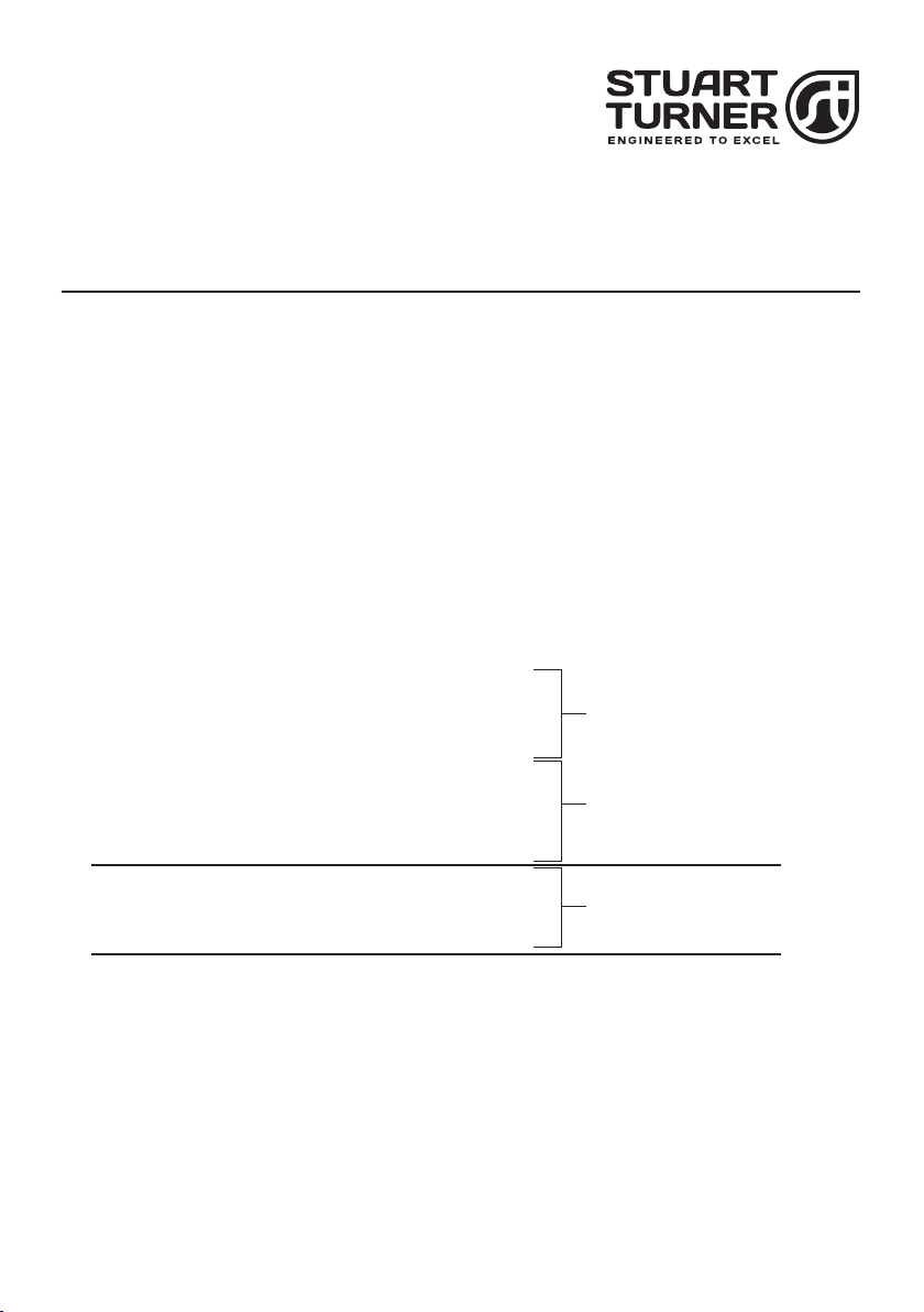
WIRING DIAGRAM
Before the removal of the flow switch manifold assembly can be achieved, the pressure
switch must be disconnected electrically and removed as shown:
Fig. Pump UK Eire
1 Monsoon Universal N2.5 bar Twin ü–
Monsoon Universal N3.5 bar Twin ü–
Monsoon Universal N4.1 bar Twin ü–
Monsoon Universal N1.5 bar Twin – ü
Monsoon Universal N2.5 bar Twin – ü
Monsoon Universal N3.5 bar Twin – ü
Monsoon Universal N4.1 bar Twin – ü
Monsoon U1.5 bar Twin üü
Monsoon U2.0 bar Twin üü
Monsoon U3.0 bar Twin üü
Monsoon U4.0 bar Twin üü
Monsoon U4.5 bar Twin üü
2 Monsoon Universal N1.5 bar Twin – ü
Monsoon Universal N2.5 bar Twin – ü
Monsoon Universal N3.5 bar Twin – ü
Monsoon Universal N4.1 bar Twin – ü
Manufactured from
November 2008
Manufactured from
October 2009
Manufactured up to
October 2008
- 2 –
Cont ...
FLOWSWITCH
REED (S3)
LINK WIRE (BLUE)
BROWN
GREEN / YELLOW
BLUE
BROWN L
S2 S3 S3 S2
E
N
230 VAC/1PH/50Hz
SUPPLY
NM
NL
S1 S1
FLOWSWITCH
REED (S2)
PRESSURE
SWITCH (S1)
MOTOR CAPACITOR
BLACK
BLUE
DISASSEMBLY
• Isolate electrical supply before fitting replacement part.
• Replacing the terminal box part components should only be carried out
by a competent person.
• The supply cord and internal wiring within the terminal box are routed
and secured to ensure compliance with the electrical standard
EN 60335–1. It is essential that prior to any disturbance of this internal
wiring, all cable routing and securing details are carefully noted to
ensure reassembly to the same factory pattern is always maintained.
FLOWSWITCH
REED (S3)
LINK WIRE (BLUE)
BROWN
GREEN / YELLOW
BLUE
BROWN L
S2 S3 S3 S2
E
N
230 VAC/1PH/50Hz
SUPPLY
NMNL
S1 S1
FLOWSWITCH
REED (S2)
PRESSURE
SWITCH (S1)
MOTOR CAPACITOR
BLACK
BLUE
Fig. 2
Pressure Switch S1
Reed Switch S3
Reed Switch S2
Fig. 1
Pressure Switch S1
Reed Switch S3
Reed Switch S2
- 3 –
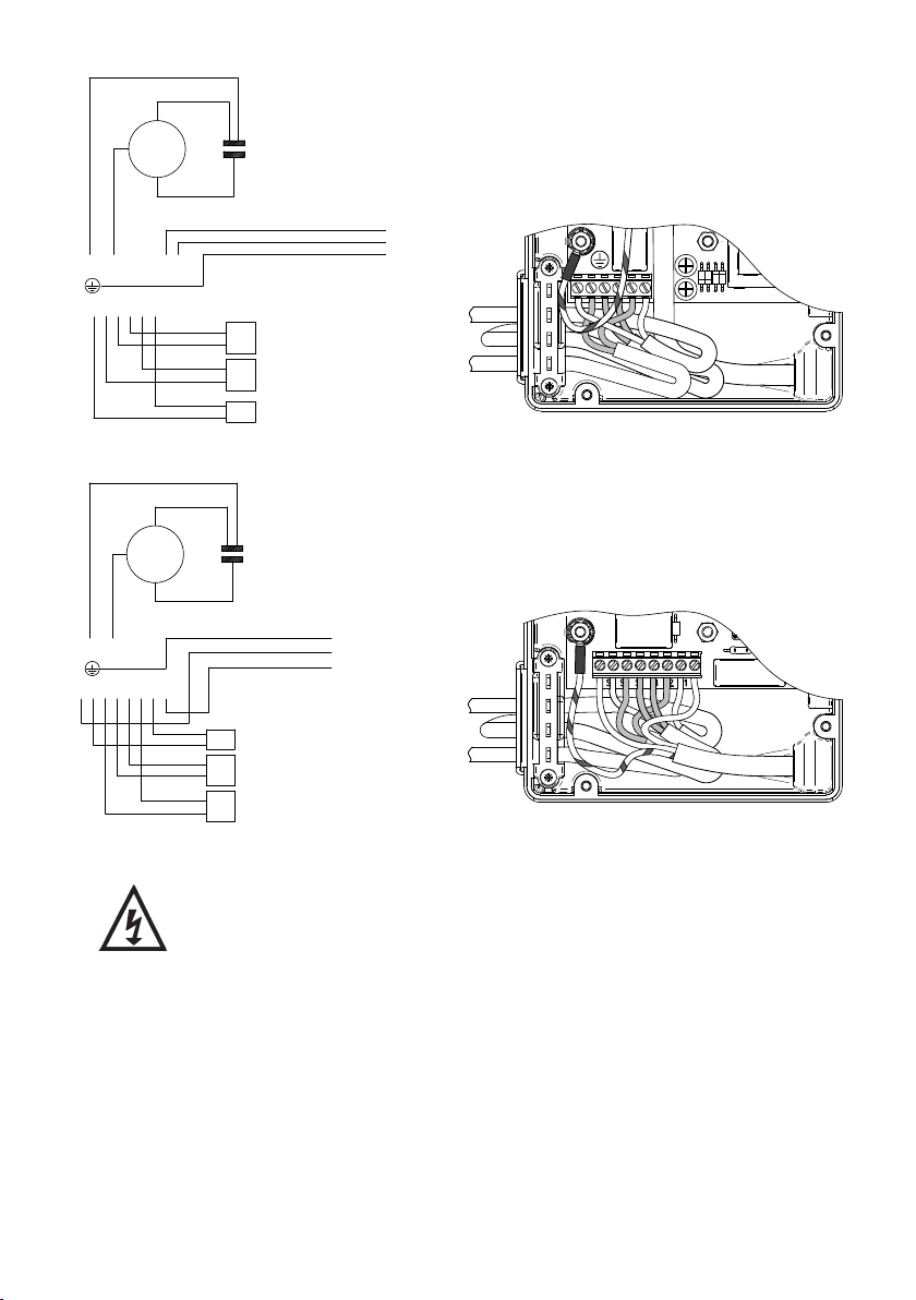
• Remove four screws and carefully remove terminal box lid (Fig. 3).
• Note the cable routing within the terminal box (Figs. 1 or 2).
• Identify and remove the pressure switch wiring from the terminal block (Figs. 1 or 2).
• IMPORTANT – take note of the cable clamp position before removal, as reassembly in
the original factory orientation is essential – Remove two screws and cable clamp (Fig. 3).
• Remove the pressure switch cable from the terminal box by gently sliding the cable out
through the sealing grommet, ensuring no damage to the seal area (Figs. 1, 2 & 3).
LN
MN
Fig. 3
4 Terminal
box lid screws
(item 8)
Terminal box lid Cable clamp screws
Cable clamp
Sealing Grommet
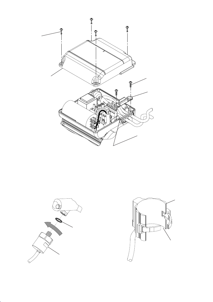
Pressure Switch Removal.
• Unscrew the pressure switch
and remove with ‘O’-ring from
the flow switch manifold (Fig 4).
Reed Switch Removal.
• Remove the reed switch by
cutting the securing tie wrap
and pulling away from flow
switch body (Fig 5).
Fig. 4 Fig. 5
‘O’-ring
Pressure switch
Reed
switch
Cut tie wrap
- 4 –
Cont ...
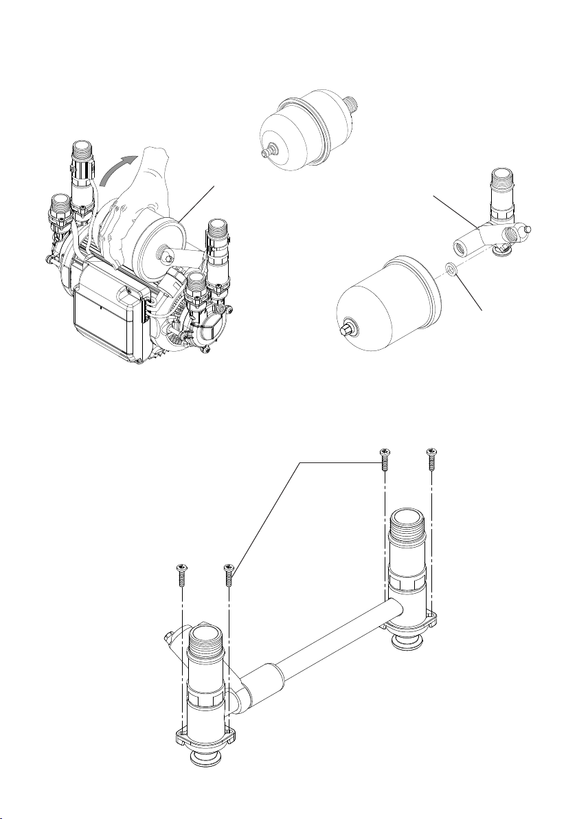
Pressure Vessel Removal.
• Unscrew and remove the pressure vessel as shown in Fig. 6.
• Note rubber washer location in manifold body (Fig. 7).
Flow Switch Assemblies Removal.
To remove the flow switch manifold, body and transfer pipe assembly.
• Remove four manifold clamp screws (A) and lift complete assembly away from pump
assembly (Fig. 8).
Fig. 6 Fig. 7
Pressure vessel Manifold body
Rubber
washer
Fig. 8
A

- 5 –
Cont ...
Disassembly of the flow switch manifold, body and transfer pipe assembly.
• Remove the transfer pipe from the flow switch manifold (Fig. 9).
• Remove the 15 mm ‘O’-ring from the flow switch manifold ensuring no damage to the
manifold parts, using ‘non-metallic’ tools (no sharp objects) (Fig. 8).
Fig. 9
Flow switch body
‘O’-ring
Transfer pipe
Flow switch
manifold
Damaged components must be replaced. Contact Stuart Turner for advice on
replacements not supplied with kit.
This manual suits for next models
1
Popular Service Equipment manuals by other brands

Magneti Marelli
Magneti Marelli ATF EXTRA PRO user manual

Hyundai
Hyundai Midtronics GRX-5100 instruction manual

Tronair
Tronair 01-1229-0011 Operation & service manual

ULTIMATE SPEED
ULTIMATE SPEED HG02236 Assembly and Safety Advice

CEMB
CEMB DWA1000CWAS manual

Invacare
Invacare TDX SP Assembly, installation and operating instructions


