Stuv 37105501 User manual

BOLZENSCHLIESSUNG
FÜR KÜHLRAUMSCHIEBETÜREN
Montageanleitung
LOCKING BOLT
FOR COLD ROOM SLIDING DOORS
Installation Instruction

- 02 -
DEUTSCH
Lesen Sie diese Montageanleitung bitte genau durch und befolgen Sie die angege-
benen Schritte.
Bewahren Sie alle Unterlagen für späteren Gebrauch auf.
Das Produkt wurde für Lagerung und Versand durch die Verpackung geschützt.
Alle verwendeten Materialien sind umweltverträglich und recyclebar. Bitte helfen
Sie mit und geben Sie die Verpackung in die entsprechenden Wertstoffbehälter.
Installation
Falls Sie Unterstützung bei der Installation des Produktes benötigen, wenden Sie
sich bitte an die Steinbach & Vollmann GmbH & Co. KG. Die Kontaktdaten nden
Sie auf der Rückseite dieser Montageanleitung.
Veränderungen an den Produkten, insbesondere Nichtbeachtung der Montageanlei-
tung, führen zum Verlust etwaiger Garantie- und Gewährleistungsansprüche.
Videoanleitung
Auf unserer Homepage nden Sie eine Videoanleitung.
Diese bendet sich im Shop in der Produktdetailansicht.
Direkten Zugang erhalten Sie durch Scannen des QR-Codes.
EINFÜHRUNG

- 03 -
DEUTSCH
LIEFERUMFANG
Bitte prüfen Sie vor Montagebeginn zunächst den Lieferumfang:
1 Außengehäuse 1 Innengehäuse 2 Dichtungen
1 Schließbolzen 1 PUSH-Aufkleber 4 Schrauben
1 Reedkontakt
(nur Magnetversion)

- 04 -
DEUTSCH
TEILE
Die im modernen und leicht zu reinigenden Design entwickelte Konstruktion be-
steht konsequent aus nicht rostenden Werkstoffen. Die speziell für Schiebetüren
entwickelte Bolzenschließung eignet sich für Türstärken von 76-100 mm.
Sie lässt sich rechts oder links einsetzen, hat eine integrierte Notöffnung und
kann optional mit Magneten zur elektronischen Verschlusszustandsanzeige aus-
gerüstet werden.
Die Bolzenschließung wird komplett mit eingebautem Prolzylinder und drei Ein-
zelschlüsseln geliefert.
PUSH Aufkleber
Innengehäuse
Außengehäuse
Dichtung
Dichtung
Mitnehmer
Schließbolzen-
Schrauben
BITTE BEACHTEN SIE UNBEDINGT DIE EINZELNEN MONTAGESCHRITTE UM
EINE EINWANDFREIE FUNKTION ZU GEWÄHRLEISTEN!
Innengehäuse-
Schrauben
- 05 -
DEUTSCH
INSTALLATION
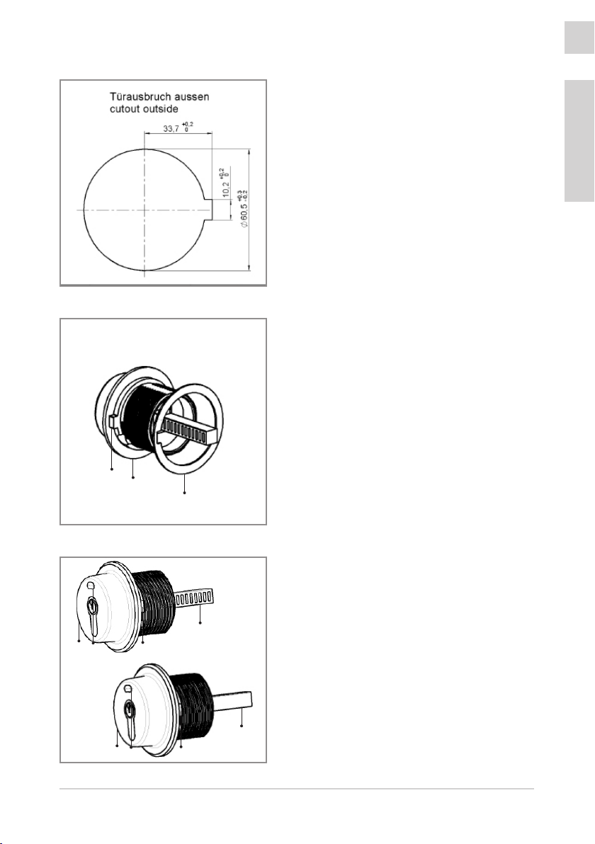
1. Schritt
Für die Verschlussaufnahme ist ein kreis-
runder Türausbruch mit einem Durchmesser
von 60,5 mm vorzusehen. Auf der Türau-
ßenseite ist zusätzlich auf der rechten Seite
eine Aussparung für die Arretierung der
Verdrehsicherung erforderlich.
2. Schritt
Legen Sie den Dichtungsring 1rückseitig
auf das Außengehäuse 2. Achten Sie dar-
auf, dass der Einschnitt im Ring über dem
Zapfen der Verdrehsicherung 3positioniert
wird.
3. Schritt
Führen Sie das Außengehäuse 2in die Tür.
Achten Sie auf folgende Einbausituation:
rechte Version: die grüne Achse 4ist mit den
Nuten seitlich zu positionieren, Schaufenster
5zeigt ROT.
linke Version: die grüne Achse 4ist mit Nuten
nach oben zu positionieren, Schaufenster 5
zeigt ROT.
Achten Sie auf die korrekte Positionierung der
Verdrehsicherung 3.
R
L
1
2
3
4
4
3
3
2
2
5
5

- 06 -
DEUTSCH
4. Schritt
Legen Sie den Dichtungsring 6 rückseitig
auf das Innengehäuse 7.
Achten Sie darauf, dass der Mitnehmer 8in
ausgefahrener Position steht.
Bei der Magnetversion müssen die beiden
Magnete 9im Mitnehmer 8außerdem
waagerecht stehen.
5. Schritt
Führen Sie das Innengehäuse 7vorsichtig
in die Tür ein. Halten Sie dabei den Mitneh-
mer 8so, dass beide Magnetbohrungen 9
in waagerechter Position stehen.
Schrauben Sie durch Gegenhalten des Au-
ßengehäuses das Innengehäuse ein, bis der
Außenring 10 mit den zwei Schraublöchern
fest auf dem Türblatt auiegt.
6. Schritt
Verschrauben Sie das Innengehäuse 7mit
den beiliegenden Schrauben 11 mit der
Türinnenseite.
INSTALLATION
67
9
9
8
710
99
8
7
11
11

- 07 -
DEUTSCH
7. Schritt
nur Version mit Magnet
Achten Sie bei der Justage des Reedkon-
taktschalters 13 darauf, dass die Entfer-
nung zum Schließbolzen 12 max. 10 mm
beträgt.
Die seitliche Entfernung der Montageplatte
14 des Reedschalters darf bis zur Mitte des
Schließbolzens 12 über alles max. 34 mm
betragen.
8. Schritt
Drücken Sie den Mitnehmer 8 ins Gehäuse.
Achten Sie dabei unbedingt darauf, dass
beide Magnetbohrungen weiterhin hori-
zontal stehen. Der Mitnehmer darf sich
beim Hineindrücken nicht verdrehen.
1312 14
INSTALLATION
Schließen Sie vor den nachfolgenden
Schritten unbedingt erst Schritte 1-6 (7) ab!
8
!

- 08 -
DEUTSCH
INSTALLATION
Detail
halbkreisförmige Schraubnuten
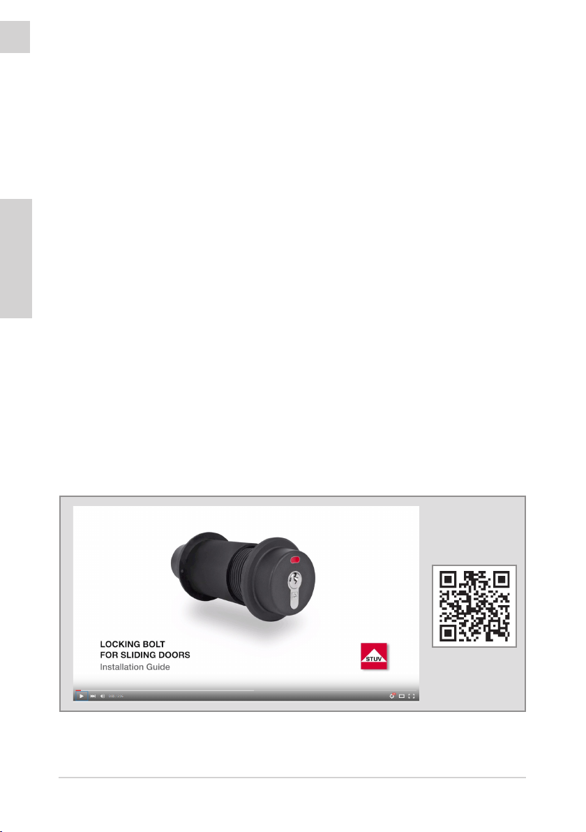
9. Schritt
Stecken Sie den Schließbolzen 12 erst jetzt
über den Mitnehmer 8. Achten Sie bei der
Positionierung darauf, dass je ein Schraubloch
über den halbkreisförmigen Schraubnuten 16
liegt.
Verschrauben Sie den Mitnehmer 8mit
beiliegenden Schrauben 11 und führen Sie
jetzt eine Funktionskontrolle durch.
Führen Sie diese Kontrolle bei montierter
Tür ausschließlich mit einer zweiten Person
auf der Außenseite durch.
12
816
1111
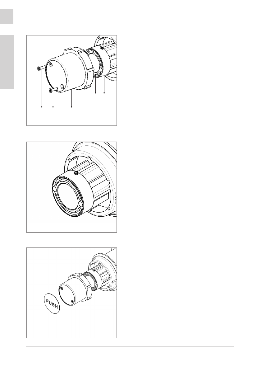
10. Schritt
Fixieren Sie zuletzt den PUSH-Aufkleber 17
in der vorgesehenen Vertiefung.

- 09 -
DEUTSCH
INSTALLATION
- 10 -
ENGLISH
INTRODUCTION
Please read these assembly instructions carefully and follow the indicated steps.
Keep all documents for future reference.
The product has been protected by packaging for storage and shipment. All ma-
terials used are environmentally compatible and recyclable. Please help to protect
our environment and put the packaging in the appropriate recycling container.
Installation
If you need any assistance during the installation of the product, please contact
Steinbach & Vollmann GmbH & Co. KG. Contact details can be found on the back
side of this brochure.
Any changes made to the product or disregard of the installation steps lead to loss
of warranty and guarantee claims.
Video Tutorial
On our website you can nd a video tutorial.
It can be found in the shop in the product detail view.
The direct access is available by scanning the QR code.

- 11 -
ENGLISH
ITEM CHECK LIST
Prior to assembling check the scope of delivery rst please.
1 Outside case 1 Inside case 2 Gaskets
1 Cam 1 PUSH-Sticker 4 Screws
1 Reed contact
switch
(for locking bolt with
magnets only)

- 12 -
ENGLISH
PARTS
The developed construction has a modern design which can be cleaned easily
and it consists consequently of non-corrosive materials. The locking bolt which is
specically developed for sliding doors is suitable for door thicknesses between
76 and 100 mm.
It can be installed either on the right or left hand side. In addition, it has an inte-
grated emergency opening and it can optionally be equipped with magnets that
display electronically the status of the locking.
The locking bolt for sliding doors is delivered with an installed prole cylinder and
three single keys.
PUSH Sticker
Inside case
Outside case
Gasket
Gasket
Cam
Cam Screws
PLEASE FOLLOW EACH INSTALLATION STEP CAREFULLY TO ENSURE
PROPER FUNCTION.
Inside Case
Screws

- 13 -
ENGLISH
INSTALLATION
1. Step
Drill a hole of 60,5 mm through the door.
Additionally prepare a cutout of 10 mm in
the outer doorleaf to protect the locking
bolt from twisting.
2. Step
Place the gasket 1backwards on the out-
side housing 2. Take care, that the groove
in the gasket is placed correctly onto the
square 3of the twisting device.
1
2
3
R
L
4
4
3
3
2
2
5
5
3. Step
Place the outside housing 2in the door. Fol-
low the instructions below:
Right hand version: Place the green axe 4
with the grooves to the side. Lock indicator 5
shows red.
Left hand version: Place the green axe 4with
the grooves to the top. Lock indicator 5shows
red.
Make sure that the anti-rotation device 3 is
positioned in a correct way.

- 14 -
ENGLISH
4. Step
Place the gasket 6 backwards on the inside
case 7.
Make sure that the cam 8is driven out.
By using the version with magnets, both
magnets 9must stay horizontal in the cam
8.
5. Step
Place the inside case 7 carefully in the door.
Keep the cam 8in that way, that both mag-
net drillings 9are in the horizontal position.
Screw, by holding the outside case, the
inside case in until the outside ring 10 with
the two holes for the screws lays tight on
the door leaf.
6. Step
Secure the inside case 7with the screws
11 on the inside of the door.
INSTALLATION
67
9
9
8
710
99
8
7
11
11

- 15 -
ENGLISH
7. Step
Locking bolt with magnets only!
Take care of the correct positioning of
the reed contact switch 13. The distance
between the locking bolt 12 and the reed
contact should be max. 10 mm.
The distance on the side of the mounting
plate 13 and the reed contact switch may
only have a maximum distance to the cen-
ter of the locking bolt 12 from 34 mm.
8. Step
Push the cam 8 into the inner housing.
Make sure that both magnet holes are
still horizontal. The cam must not twist
when pressing in.
1312 14
INSTALLATION
Make sure to nish steps 1-6 (7) completely
before proceeding!
!
8
- 16 -
DEUTSCH
INSTALLATION
Detail
semicircle screw grooves
9. Step
Insert the locking bolt 12 only now over the
cam 8. Make sure, that both drilling holes
are placed over the semicircle of the screw
grooves 16.
Tighten the cam 8with the enclosed screws
11 and carry out a functional check.
Make this test by a mounted door only
with a second person on the outside of
the door!
12
816
1111
10. Step
Place the “PUSH” sticker 17 in the
corresponding hollow.

- 17 -
ENGLISH
NOTES

Steinbach & Vollmann
GmbH & Co. KG
Schloß- und Beschlägefabrik
Parkstraße 11
42579 Heiligenhaus
Germany
Telefon +49 2056 14-0
Telefax +49 2056 14-251
E-Mail info@stuv.de
Internet www.stuv.de
08/2018 Printed in Germany
Zumutbare Abweichungen in Modellen und Farben sowie Änderungen zur Anpassung an den neuesten Stand der Technik
und Produktion bleiben ausdrücklich vorbehalten.
Copyright © 2018 Steinbach & Vollmann
Dieses Handbuch darf weder als Ganzes noch in Auszügen ohne schriftliche Genehmigung von Steinbach & Vollmann
reproduziert, vertrieben, übersetzt oder in anderer Art und Weise oder mit anderen Mitteln elektronischer oder mechanischer
Art übertragen werden. Dies schließt Fotokopien, Aufzeichnungen oder Speichern in jedweder Art ein.
This manual suits for next models
2
Table of contents
Languages:
Other Stuv Door Lock manuals


Popular Door Lock manuals by other brands


Gainsborough
Gainsborough SD8 ILLUSTRATED FITTING INSTRUCTIONS

Ingersoll-Rand
Ingersoll-Rand Schlage BE365 user guide

Cielsa Dawn
Cielsa Dawn E021 Installation and user guide

Kwikset
Kwikset 62541/01 installation guide

National Cabinet Lock
National Cabinet Lock C8173 Dimensional drawing

Opera
Opera 40600 manual


