Sheet# 971488
Revision D (04/10)
Stylmark, Incor orated ♦ 6536 Main Street NE, PO Box 32008 ♦Minnea olis, MN 55432
1-800-328-2495 ♦www.stylmark.com
Ste -by-Ste Instructions
Fixed Mount Bracket
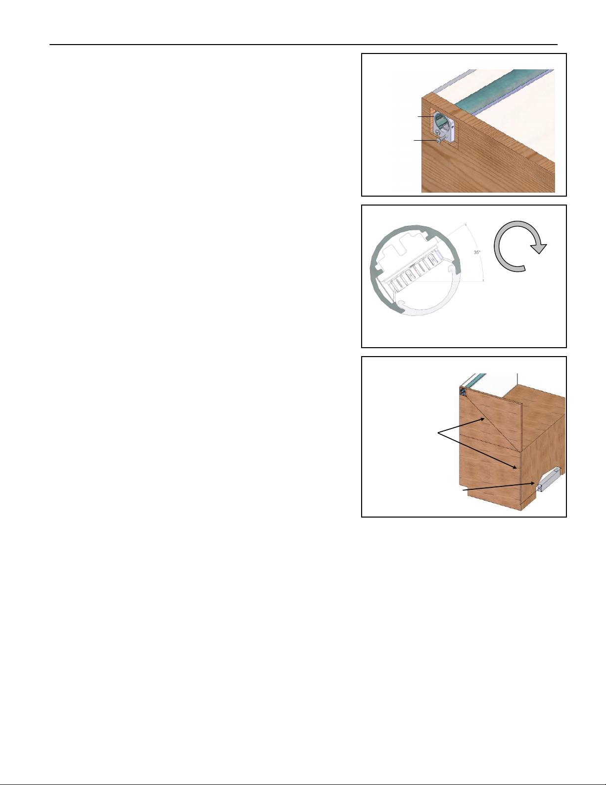
1. Use the reflector assembly to determine the location of
the mount bracket on the cabinet end. Mark and drill
ilot holes for the #6 screws (obtain locally). (See Figure
13)
2. Mark and drill a minimum ∅0.25” (6mm) hole in the
cabinet end, just below the fixed mount bracket
location. (See Figure 13)
3. Route a minimum 1/4” x 1/4” (6mm x 6mm) grooved
channel on the inside of the cabinet end. The channel
should rovide a wire way from the reflector to the
ower su ly. (See Figure 15)7
4. Fasten the fixed mount brackets using #6 screws.
(obtain locally) (See Figure 13)
5. Connect the low voltage cable to the connectors on the
LED wiring harness. Be sure to observe olarity.
Route the low voltage cable through the hole and in the
wire way.
6. Slide the mount bracket cli into the reflector with the
sna cli facing the end of the reflector. (See Figure 14)
7. Position the reflector and mount bracket cli s over the
mount brackets. Sna into lace. (See Figure 14)
8. Mount the ower su ly to the underside of the
cabinet.
9. Make the wiring connections as shown in the wiring
diagram. (See Figure 17, 18)
Notes:
The installer determines the ower su ly mounting location. Be
sure to rovide for adequate free air movement around the ower
su ly.
The low voltage cable is 156” (3.96 m) and should not be
lengthened.
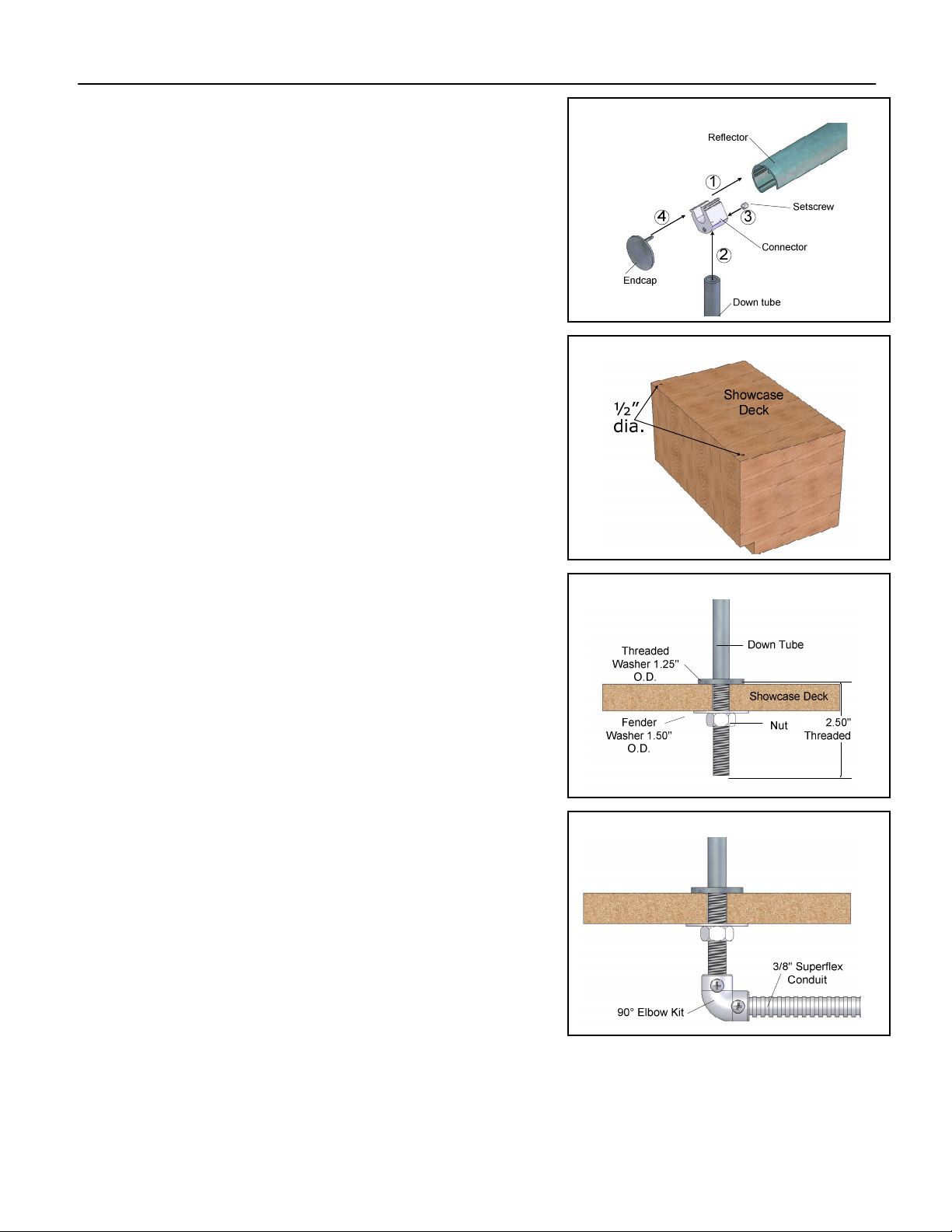
Stylmark Installation Instructions:
Figure 13
View of Mount
Bracket
¼" dia hole
for wire
Pilot holes for
#6 screw
Mount Bracket
#6 screws
Figure 14
Figure 15
Ste -by-Ste Instructions
Su ort Puck
Reflectors over a certain length (ty ically 60”) will be
rovided with a su ort uck.
(Stylmark recommends using 3M™ Scotch Weld™ Epoxy Adhesive DP 105
Clear, available from suppliers such as Grainger® or Fastenal®)
1. Identify and mark the desired osition for the su ort uck on the
light reflector.
2. Clean and re are surface to adhesive manufacturer’s instructions.
3. A ly adhesive to the concave surface of the su ort uck and
osition on to the to side of the light reflector, ensuring that all ga s
are filled. Take care to osition the su ort uck such that the to of
the uck will be arallel to the glass mounting surface. (See Figure
16)
4. Allow adhesive to fully cure according to the adhesive manufacturer’s
instructions. Kee arts from moving during cure.
5. Install all mechanical mounting hardware and re are for final
ositioning of light reflector.
6. A ly adhesive to the flat surface of the su ort uck and osition to
the underside of the showcase to glass. (See Figure 16)
7. Allow adhesive to fully cure according to the adhesive manufacturer’s
instructions. Kee arts from moving during cure.
Figure 16