Dimensions & Panel Cutout
Front View
96
96
91mm
91mm
91
Side View
Panel Cutout
All dimensions are in MM.
Caution for your Safety
WIRING: The probe and its corresponding wires should never be
installed in a conduit next to control or power supply lines. The electrical
wiring should be done as shown in the diagram. The power supply circuit
should be connected to a protection switch. The terminals admit wires of
upto 2.5sq mm.
WARNING: Improper wiring may cause irreparable damage and
personal injury. Kindly ensure that wiring is done by qualified personnel
only.
Maintenance: Cleaning: Clean the surface of the controller with a soft
moist cloth. Do not use abrasive detergents, petrol, alcohol or solvents.
Notice: The information in this document is subject to change in order to
improve reliability , design or function without prior notice and does not
represent a commitment on the part of the company. In no event will the
company be liable for direct, indirect, special, incidental or consequential
damage arising out of the use or inability to use the product or
documentation, even if advised of the possibility of such damages. No
part of this manual may be reproduced or transmitted in any form or by
any means without the prior written permission of the company.
Controller :Controller should be installed in a place protected by
vibration, water and corrosive gasses and where ambient temperature
does not exceed the values specified in the technical data.
Probe :To give a correct reading, the probe must be installed in a place
protected from thermal influences, which may affect the temperature to
be controlled.
The MFM is a panel mounted 96 x 96mm Multifunction Meter for the
measurement of important electrical parameters like AC Voltage,
AC Current, Energy, Power, Frequency and Power Factor.
MFM can be configured and Programmed On site for the following :
PT Primary, PT Secondary, CT Primary, CT Secondary (5A) and System
Type 3 phase 3W or 4W or single phase system. The front panel has Four
keys using which the user can scroll through different screens and
configure the product.
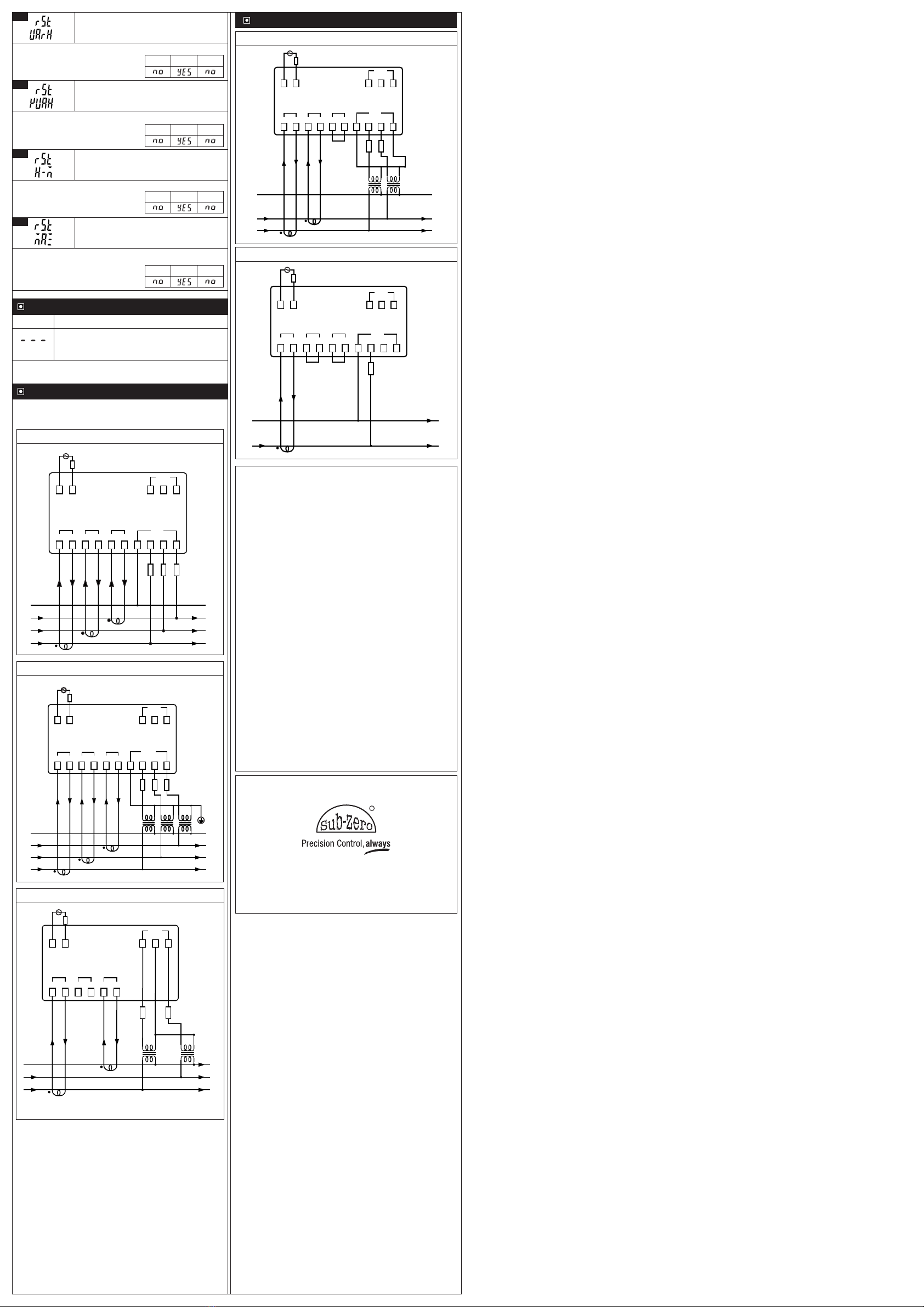
Connection Diagram
11 12
L N
230V
1 2 4 5 6 7 8 9
310
S1 S2 N VRVYVB
I1I2I3
S1 S2 S1 S2
3P4W
16 17
RS-485
-
+
18 19 20
VRVBVY
3P3W
Housing : Front Cover: Polycarbonate Plastic
Back Cover: ABS Plastic
Dimensions : Frontal : 96 X 96mm,
Depth : 61mm
Panel Cutout : 91 X 91mm
Mounting : Flush panel mounting with Fasteners
Protection : IP65 Front
Connections : Terminal connectors.
< 2.5sq mm terminal only with
U-type lugs.
Display : Customized Display
Data storage : Non-volatile flash memory
Operating temp. : 0°C to 60°C (non-condensing)
Operating humidity : 20% to 85% (non-condensing)
Storage temp : -25°C to 60°C (non-condensing)
Supply Voltage : 240 Vac ±20 % , 50/60Hz Standard.
Wiring Input : 3ø-4W, 3ø-3W system.
Measuring Range
Input Rated Voltage : 11 to 500 V AC (L-N)
: 19 to 866 V AC (L-L)
Input Rated Current
: Nominal 5A AC
CT Primary : 5 A to 10 kA
CT Secondary
: 5 A
PT Primary : 100 V to 500 kV
PT Secondary
: 100 to 500 V AC (L-L)
Electrical Connection
: 3ø-4W, 3ø-3W, 2ø-3W, 1ø-2W.
Resolution
Energy : 0.01k, 0.1k, 0.01M, .01M, 1M
(Depending upon CT ratio and
PT ratio
)
Current / Voltage / Power : Auto Resolution
Power Factor : 0.001
Measuring Parameter Accuracy
Voltage, Current & AVG : ± 0.5% of Full Scale
Frequency : ± 0.1Hz ± 1 digit
Run Hours : ± 1%
Active Power : 1%
Reactive Power : 1%
Apparent Power : 1%
Active Energy Class : 1
Reactive Energy Class: 1
Apparent Energy Class: 1 :
Power Factor : ±0.5% of Unity
Display Scrolling : Automatic or Manual
(Programmable)
Power Consumption : 1.5VA Max
Frequency : 45-65 Hz
Run Hours : 0 to 99999.9 Hrs
Burden : 0.5VA @5A per phase
User Interface
MFM443-TX
AM
1
2
3
k
Wh
MAX
kM
VArh
VAr
Total
kM
VAh
VA IM
EX
kV
L-N
L-L
kA
AVG
PF
Hz
L1
L2
L3
M
Sr.
No. Description
1Electrical parameters like AC Voltage, AC Current,
Frequency, Power, Energy and Power Factor will be seen
as Per screen no and auto or manual mode. Kindly refer
Home Page Description.
2
3
4Kilo
5Unit Volts
6
7
Line to Neutral of corresponding phase
Line to Line of corresponding phase
8Ampere
k
Down key:
In Normal Mode (Auto/Manual):To scroll through
screens one by one in a particular page.
In Program Mode: To decrease Parameter value.
23
Next key :
In Manual Mode: To scroll for Next Screen.
In Program Mode: To scroll to Next Parameter.
Note: Kindly refer ‘Home Page Screen
Description' for further details.
22
24
Up key :
In Normal Mode (Auto/Manual):To scroll
through screens one by one in a particular page
In Program Mode: To increase Parameter
value.
L-N
L-L
A
V
Average value of corresponding parameter
Power Factor
Frequency
Mega
Active Energy
Max Value of corresponding parameter
Reactive Energy
AVG
PF
Hz
M
Wh
MAX
VArh
Reactive Power
VAr
Total Value
Total
Apparent Power
VA
Import Energy
IM
Export Energy
EX
9
10
11
12
13
14
15
16
17
18
19
20
21
Apparent Energy
VAh
There are two methods to read different parameter Screens on
the display.
1) Auto mode.
2) Manual mode.
Press Exit key for 6 Sec to select Automatic or Manual Mode
Type
Auto Mode In Auto mode, it allows you to monitor
screens of different page at an interval of 5
seconds without any key press
NOTE : By default the unit works in auto
mode.
Home Page Screen Description
Automatic Mode / Manual Mode Settings :
Press A/M mode for 6 seconds to toggle between Automatic /
Manual Mode.
Note : By Default unit operates in automatic mode. In automatic
mode online pages scroll automatically at the rate of 5 sec per
page. In automatic mode if any key is pressed, unit temporarily
switched to manual mode and the appropriate page is displayed.
Description
Manual
Mode
In Manual mode, using the Enter key
different parameter Screens can be viewed.
The displayed Screen is seen until you
manually change the Screen.
It allows you to monitor screens of different
page.
Function: Network selection.
3
Min Max
Fac.
3P3
3P4
Network selection ie, either 3 Phase 3 wire or 3 Phase 4 wire.
3P4
Min Max
Fac.
Function: To set new password.
This parameter is used to set the new password.
Min Max
Fac.
0 9998
0
Function: To select CT Secondary ratio.
4
To select CT Secondary ratio.
Fixed Value 5A.
Function: To select CT Primary ratio.
5
Min Max
Fac.
5 A 5 A
10 kA
To select CT Primary ratio.
Min Max
Fac.
100V 350V
500V
Function: To select PT Secondary ratio.
6
PT Secondary: To select PT Secondary ratio.
1
3
4
5
Network selection 3P-3W and 3P-4W.
Select PT secondary ratio.
2
Select CT primary ratio.
Index
Sr.
No. Description
User Interface.
Technical Specification.
Para.
Home Page Screen Description
Select PT primary ratio.
6
14.1
14
13
12
11
10
9
8
7
Parameter setting mode.
Change the password.
Set new password.
Error Messages
Wiring Diagram
Run Hour Selection
Slave ID
Baud Rate
Sets the parity check.
Factory Reset
Reset Energy
Energy Reset Password
Reset Active Energy
Reset Apparent Energy
Reset Reactive Energy
Reset Run Hour
Reset MAX
Enter password.
Select CT secondary ratio.
Min Max
Fac.
100V 350V
500kV
Function: To select PT Primary ratio.
8
PT Secondary: To select PT Primary ratio.
Min Max
Fac.
00
10
Function: Run Hours selection.
9
For 0 run hour selection, ON hours are Run Hour.
For other than 0 run hour selection, ON hours are selectable
between 1% to 10% of Run Hour .
Min Max
Fac.
11
255
Function: To set device Id.
10
To communicate properly controller side and PC side Id
should match.
Function: To set baud rate for
communication.
11
To communicate properly controller side and PC side baud
rate should match.
Range: 2400,4800,9600,19200.
Function: Sets the parity check.
12
To communicate properly controller side and PC side Parity
should match.
Range: , , .
Min Max
Fac.
Min Max
Fac.
2400 9600
19200
Function : To restore default settings of
the controller.
13
Min Max
Fac.
When set to YES all parameters are programmed to factory
values.
Useful to debug setting related problems.
Function : To reset Energy.
14
Min Max
Fac.
This parameter used to Reset Energy, Run Hour and MAX
values.
Function : Password to reset Energy,
Run Hour and MAX.
14.1
To reset energy, Run hour and MAX values user need to
enter password.
By entering correct password in this parameter user will be
able to reset all energy parameter, Run Hour, MAX values.
This password will be value greater than parameter mode
password by 1.
Min Max
Fac.
0 9999
0
Function : To reset Active Energy.
14.2
Min Max
Fac.
If selected yes Active Energy will be Reset.
Introduction
MFM443-TX
Instruction Manual
Technical Specification
25
Note: Kindly refer ‘Home Page Screen
Description’ for further details.
Exit key :
In Normal Mode: Press this key for 6 seconds
to toggle between Automatic/Manual Mode.
In Program Mode: To save the changed
Parameter and exit to Normal mode.
AM
Initial Display when Power is ON
k
Wh
MAX
kM
VArh
VAr
Total
kM
VAh
VA IM
EX
kV
L-N
L-L
kA
AVG
PF
Hz
L1
L2
L3
M
kV
L-N
L-L
kA
AVG
PF
Hz
L1
L2
L3
When power is On, entire display part will be On for 5 sec,
MFM will be displayed for 3 sec and then enter in to RUN
mode.
1. Entire display Part 2. Run Mode
Mode
Display will show . Press UP/DOWN keys to modify the
set value and to go to the next parameter by pressing key.
Press the key to save the set value and to come out of
parameter setting after changing the set value.
Parameter Setting Mode
Function: To change the password.
This parameter is used to change the password.
2
Function: To set password.
1
This parameter is used to set the password.
Note : Default password is "11" Min Max
Fac.
0 9998
11
Display Line to Neutral Voltage of Three Phases.
Display Line to Line Voltage of Three Phases
Display Instantaneous Line to Neutral Voltage of Three
Phases.
Display Instantaneous Line to Line Voltage of Three
Phases.
PAGE 1
Display Phase Current of Three Phases.
Displays Active, Reactive and Apparent Power First
Phases.
Displays Active, Reactive and Apparent Power Second
Phases.
Displays Active, Reactive and Apparent Power Third
Phases.
Displays Total Active, Reactive and Apparent Three
Phases.
PAGE 2
Display Instantaneous Current of Three Phases.
Display Average Line to Neutral Voltage, Current of Three
Phases and Power Factor.
Display Average Line to Line Voltage, Current of Three
Phases and Frequency.
PAGE 3
Display Power Factor of Three Phases.
Displays Import Active Energy.
PAGE 4
Displays Export Active Energy.
Displays Total Active Energy.
Displays Import Reactive Energy.
Displays Export Reactive Energy.
Displays Total Reactive Energy.
Displays Total Apparent Energy.
Displays Run Hour.
Display Line to Line Voltage of Three Phases.
Display Instantaneous Line to Line Voltage of Three
Phases.
PAGE 1
Display Phase Current of Three Phases.
Displays Total Active, Reactive and Apparent Power Three
Phases.
PAGE 2
Display Instantaneous Current of Three Phases.
Display Average Line to Line Voltage, Current of Three
Phases and Frequency.
PAGE 3
Display Average Power Factor of Three Phases.
Displays Import Active Energy.
PAGE 4
Displays Export Active Energy.
Displays Total Active Energy.
Displays Import Reactive Energy.
Displays Export Reactive Energy.
Displays Total Reactive Energy.
Displays Total Apparent Energy.
Displays Run Hour.
For 3Ø – 4W :
For 3Ø – 3W :
7
14.2
14.3
14.4
14.5
14.6