SunFounder Rollarm User manual

www.sunfounder.com
Preface
About SunFounder
SunFounder is a technology company focused on Raspberry Pi and Arduino open source
community development. Committed to the promotion of open source culture, we strive to
bring the fun of electronics making to people all around the world and enable everyone to
be a maker. Our products include learning kits, development boards, robots, sensor
modules and development tools. In addition to high quality products, SunFounder also offers
video tutorials to help you build your own project. If you have interest in open source or
making something cool, welcome to join us! Visit www.sunfounder.com for more!
About This Kit
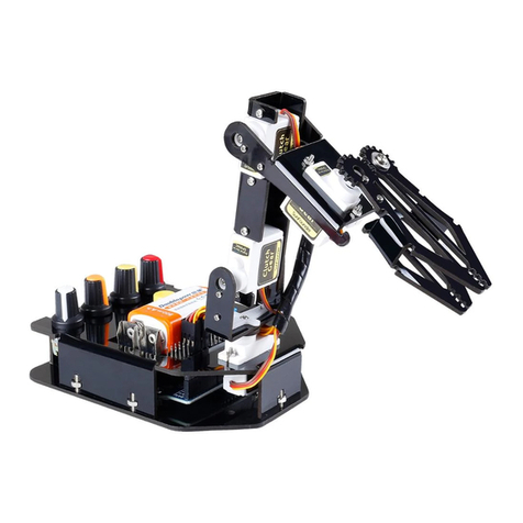
The Rollarm Kit for Arduino is designed for mass hobbyists to learn robot arm control. With
the open source MCU Arduino UNO and a servo expansion board, the robot arm is easy to
use and full of fun. You can control its four axes by the 4 potentiometers on the handle, as
well as make them move on your computer. In addition, it can memorize the movements
it's made and repeat again and again, making it a great tool for repeated tasks.
In this book, you can learn the basics of how a mechanical arm works and how to make
one piece by piece. For more information, please go to our website www.sunfounder.com
and find the tutorial under LEARN -> Get tutorials. Also video tutorials about the assembly
and playing are provided under VIDEO -> Robot Kit -> DIY Control Robot Arm Kit for Arduino-
Rollarm.
Free Support
If you have any TECHNICAL questions, add a topic under FORUM section on our
website and we'll reply as soon as possible.
For NON-TECH questions like order and shipment issues, please send an email to
service@sunfounder.com. You're also welcomed to share your projects on FORUM.

www.sunfounder.com
Contents
1. Introduction .................................................................................................................................... 1
1.1 Overview .......................................................................................................................... 1
2. Components List............................................................................................................................ 2
2.1 Acrylic Plates ................................................................................................................... 2
2.2 Connecting Components ........................................................................................... 3
2.3 Electronic Components ............................................................................................... 5
2.4 Tools ................................................................................................................................... 7
2.5 Self-Provided Components ......................................................................................... 7
3. How to Control............................................................................................................................... 8
4. Getting Started with Software ................................................................................................... 8
4.1 Arduino ............................................................................................................................. 8
4.1.1 Description ............................................................................................................... 8
4.1.2 Install Arduino IDE ................................................................................................... 8
4.2 Resources Download.................................................................................................. 12
5. Assembly........................................................................................................................................ 13
5.1 Base Bottom Plate + Riband ..................................................................................... 13
5.2 Base Bottom Plate + Battery Holder ....................................................................... 13
5.3 Base Bottom Plate + Circuit Board.......................................................................... 14
5.4 Base Bottom Plate + Base Fixing Plate ................................................................... 15
5.5 Base Upper Plate + Servo .......................................................................................... 16
5.6 Base Fixing Plate + Base Upper Plate ..................................................................... 17
5.7 Joint 1-Connecting Plate + Servo Rocker Arm .................................................... 18
5.8 Joint 1 Connecting Plate ........................................................................................... 19
5.9 Base + Joint 1 Connecting Plate ............................................................................. 20
5.10 Joint 2 + Right Joint Plate 2 ....................................................................................... 23
5.11 Joint 1 Connecting Plate + Joint 2 Connecting Plate....................................... 26
5.12 Joint 1 Connecting Plate ........................................................................................... 28
5.13 Gripper Fixing Plate ..................................................................................................... 29
5.14 Gripper Driving Plate + Gripper Driven Plate ....................................................... 30
5.15 Grippers + Gripper Fixing Plate ................................................................................ 33
5.16 Gripper Fixing Plate + Right Joint Plate 3............................................................... 35
5.17 Joint 2 Connecting Plate + Joint 3 Connecting Plate....................................... 36
5.18 Left Joint Plate 3 ........................................................................................................... 37
5.19 Handle............................................................................................................................. 38
5.20 Wiring............................................................................................................................... 42
6. Control the Rollarm..................................................................................................................... 43
6.1 Manual Control ............................................................................................................ 43
6.2 Automatic Control....................................................................................................... 44
6.3 Code Explanation........................................................................................................ 45
6.4 PC Control (by Labview) ........................................................................................... 48
6.4.1 Installing Labview Software ............................................................................... 48
6.4.2 Running the Labview........................................................................................... 49

www.sunfounder.com
1
1. Introduction
1.1 Overview
The Rollarm Kit is an interesting and useful learning tool for Arduino and robot hobbyists. With
the acrylic design and code based on Arduino, it enables users to learn programming from
easy to difficult, control the mechanical arm freely and perform various fun operations!
This fun mechanical arm consists of 4 axes, each controlled by a servo. Powered by two
18650 batteries, the control systems is composed of SunFounder Uno board, servo extension
board, and remote control board. The kit includes all necessary components like acrylic
plates, circuit boards, and connector parts. For your better learning, installation and
debugging video tutorials are provided on our website. Also you can download the user
manual which elaborates on the installation procedures and program explanation. With
these resources, you can quickly and effortlessly make creative projects with the Rollarm.
Now let's go to get the fun!

www.sunfounder.com
2
2. Components List
2.1 Acrylic Plates
Prior to assembling the Rollarm, you need to remove the residues in the holes of the plates
and the stickers on the plates. Here we take the Joint 1 fixing plate for example.
1. Check whether there are some residues
in the holes of the acrylic plate.
2. Use a tool with a pointed end to remove
the residue.

www.sunfounder.com
3
3. Make sure that all the residues are
cleared.
4. Use the pointed tool to scratch off the
sticker on the plate.
2.2 Connecting Components
Name
Component
Qty.
M1.2*4
Self-tapping Screw
14
M2*8 Screw
8
M2 Nut
8
M3*8 Flat-Head Screw
2
M3*8 Screw
10

www.sunfounder.com
4
M3*10 Screw
18
M3 Nut
20
M7 Thin Nut
4
3*10*1 Washer
1
M3*10 Aluminum
Tube
5
M3*6 Corn Rivet
2
φ3*φ8*4 Band Edge
Bearing
3

www.sunfounder.com
5
2.3 Electronic Components
Name
Component
Qty.
SunFounder Servo
(9g)
4
Potentiometer Button
4
Button
1
18650*2 Battery
Holder
1

www.sunfounder.com
6
SunFounder Mars
Board
1
Expansion Board
1
Potentiometer
Module
1
USB Type-C Cable
1
RJ11 Cable
2
Riband
1

www.sunfounder.com
7
3M Non-skid Pad
4
Heat Shrink Tubing
2
Cable Clip
2
2.4 Tools
Screw Driver
1
2.5 Self-Provided Components
18650 Battery
2

www.sunfounder.com
8
3. How to Control
1. Install Arduino IDE
2. Assemble the Rollarm (Remember to configure the servos before assembly. Pay
attention to the detailed operations)
3. Control with handle: download the Rollarm package and run the program
(Indispensable step before operating the Rollarm)
4. Control with Labview: download the Labview to your PC and install for control
(download is a must-do before subsequent operating)
Let’s get started. Enjoy!
4. Getting Started with Software
4.1 Arduino
4.1.1 Description
Arduino is an open source platform that applies simple software and hardware. You can
get it in a short even when you know little of it. It provides an integrated development
environment (IDE) for code editing and compiling, compatible with multiple control boards.
So you can just download the Arduino IDE, upload the sketches (i.e. the code files) to the
board, and then you can see experimental phenomena. For more information, refer to
http://www.arduino.cc.
4.1.2 Install Arduino IDE
The code in this kit is written based on Arduino, so you need to install the IDE first. Skip it if you
have done this.
Step 1: Go to the arduino.cc website and click Download. On the page, check the software
list on the right side under Download the Arduino Software.

www.sunfounder.com
9
Find the one that suits your operation system and click to download. There are two versions
of Arduino for Windows: Installer or ZIP file. You're recommended to download the former.
Step 2: Double click the .exe file and the following window will show up. Click I Agree. The
following interface will show up.
Choose Next.

www.sunfounder.com
10
Click Browse to choose the installation path or enter a directory at the Destination Folder.
Click Install.
The following interface will show up. Note: After the installing progress bar goes to the end,
the Close button may be enabled for some PC. Just click it to complete the installation.

www.sunfounder.com
11
Then a prompt appears. Select Always trust software for "Adafruit Industries" and click Install.
Select Always trust software for "Arduino srl" and click Install.
After the installation is done, click Close. Then an Arduino icon will appear on the desktop:

www.sunfounder.com
12
4.2 Resources Download
1. For downloading the program, go to LEARN->Get tutorials->Robot Kit-> DIY Control
Robot Arm kit for Arduino-Rollarm and download the package:
2. Downloading the Labview software
The link for downloading (you may also find the link in the PDF file downloaded before):
https://s3.amazonaws.com/sunfounder/Arduino/Labview.zip
Note:
Labview/Rollarm/Rollarm’s Installer/setup.ex: The installer of Labview on your PC.
Then choose your installation path.
3. For related introduction and installation videos of the DIY Control Robot Arm kit for
Arduino-Rollarm, please click VIDEO -> Robot Kit -> DIY Control Robot Arm Kit for
Arduino-Rollarm.

www.sunfounder.com
13
5. Assembly
5.1 Base Bottom Plate + Riband
1. Cut the 50cm ribbon into halves. Thread the ribbon through the Acrylic plate. Leave
the riband with one end of a long part and the other of a short one. Thread another
riband through the base bottom plate.
5.2 Base Bottom Plate + Battery Holder
1. Place the battery holder on the base
bottom plate. Cling two M3 nuts
underneath the plate and keep them
aligned with the holes of the holder. Pay
attention to put the end without holder
power lines at the right side.
2. Insert two M3*10 flat-head screws into
the nuts and fasten them with the screw
driver.

www.sunfounder.com
14
3. Fold the ribbon in the battery holder.
4. Align the anode of the battery with
that of the battery cover and so does the
cathode.
5. Insert the battery into the battery holder.
5.3 Base Bottom Plate + Circuit Board
1. Align the four acrylic washers with the
holes of the base bottom plate (a spare
washed is provided in case).
2. Place the four acrylic washers on the
base bottom plate.

www.sunfounder.com
15
3. Align the acrylic washers and holes on
the plate. Cling 4 M3 nuts to the holes
underneath the plate.
4. Place the Mars board onto the plate
with its holes aligned with the washers.
Fasten them with the M3*12 screws.
5. Align the pin headers of the expansion
board with the sockets of the Mars board.
6. Insert the pin headers into the sockets.
5.4 Base Bottom Plate + Base Fixing Plate
1. Put an M3 nut in the hole of the base
fixing plate. Align its bulges with the holes
of the base bottom plate.
2. Insert the bulges into the holes. Fix the
two plates with the M3 nut and the M3*10
screw.

www.sunfounder.com
16
3. Mount the other base fixing plate in the same way.
5.5 Base Upper Plate + Servo
1. Align the servo with the slot of the base
upper plate with the rotating axis close to
the middle line of the base upper plate.
2. Insert the servo into the slot.
3. Hold an M2 nut underneath the hole of
the servo and the upper plate and insert
an M2*8 screw.
4. Fasten them with the screw driver.
5. Fasten the other screw and nut in the same way.

www.sunfounder.com
17
5.6 Base Fixing Plate + Base Upper Plate
1. Align the holes of the base upper plate
with the bulges of the base fixing plate.
2. Insert the bulges into the holes.
3. Put an M3 nut in the hole of the base
fixing plate, insert an M3*10 screw through
the plate into the nut and fasten them
with the screw driver.
4. Fasten the other screw in the same way.
5. Paste four non-skid pads onto the
corners of the base bottom plate.
6. It will be like this after pasting.

www.sunfounder.com
18
5.7 Joint 1-Connecting Plate + Servo Rocker Arm
1. Align the servo rocker arm with the
hole of the Joint 1-connecting plate.
2. Put the rocker arm on the connecting
plate and rotate it to align its holes with
those of the plate.
3. Align the holes like this:
4. Insert an M1.2*4 self-tapping screw into
a hole of the plate through the rocker
arm.
5. Fasten them with the screw driver.
6. Fasten the other self-tapping screws in
the same way.
7. Fix a servo rocker arm on the Right Joint Plate 1 in the same way.
Other manuals for Rollarm
1
Table of contents
Other SunFounder Robotics manuals

SunFounder
SunFounder PiArm User manual

SunFounder
SunFounder PiSloth User manual

SunFounder
SunFounder RollFlash User manual

SunFounder
SunFounder PiDog User manual

SunFounder
SunFounder Bionic Robot Lizard User manual

SunFounder
SunFounder 3in1 Kit User manual

SunFounder
SunFounder Sloth Learning Kit User manual

SunFounder
SunFounder RollbotMicro User manual

SunFounder
SunFounder PiCrawler Kit User manual

SunFounder
SunFounder PiCar-4WD User manual