Sungrow COM100D User manual

CCOOMM110000DD//CCOOMM110000EESSmmaarrtt
CCoommmmuunniiccaattiioonn BBooxxUUsseerr
MMaannuuaallCCOOMM110000DD__EE--UUEENN--VVeerr1122--
220022110077 VVeerrssiioonn::11..22
COM100D_E-UEN-Ver12-202107 Version:1.2
COM100D/COM100E
SSmmaarrtt CCoommmmuunniiccaattiioonn BBooxx
UUsseerr MMaannuuaall


I
CCoonntteennttss
1 About This Manual ....................................................................................... 1
1.1 Validity ......................................................................................................... 1
1.2 Type Description .......................................................................................... 1
1.3 Intended Use................................................................................................ 1
1.4 Target Group................................................................................................ 1
1.5 How to Use This Manual............................................................................... 2
1.6 Symbol Explanation...................................................................................... 2
2 Safety Instruction ........................................................................................ 3
3 Product Introduction ................................................................................... 5
3.1 Function Description .................................................................................... 5
3.1.1 Brief Introduction ................................................................................ 5
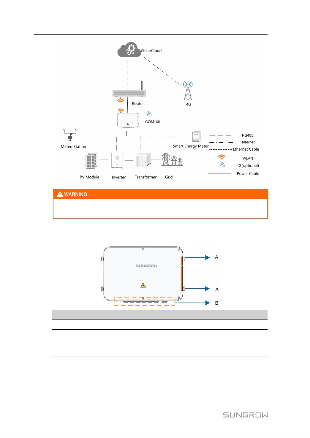
3.1.2 Networking Application....................................................................... 5
3.2 Appearance................................................................................................. 6
3.3 Dimensions.................................................................................................. 6
4 Mechanical Installation .............................................................................. 8
4.1 Unpacking and Inspection............................................................................ 8
4.2 Location Requirements ................................................................................ 9
4.3 Installation Tools........................................................................................... 9
4.4 Installation Method....................................................................................... 9
4.4.1 Wall-Mounting.................................................................................. 10
4.4.2 Pole-Mounting (Optional).................................................................. 12
4.5 Magnetic Base Antenna Connection (Optional)........................................... 13
5 Electrical Connection ............................................................................... 15
5.1 Waterproof Terminal Description ................................................................ 15
5.2 Internal Structure........................................................................................ 16
5.3 Preparation Before Cable Connection......................................................... 16
5.4 Grounding.................................................................................................. 17
5.5 External AC Power Supply Cable ................................................................ 18
5.6 RS485 Port ................................................................................................ 19
5.7 Ethernet Port.............................................................................................. 19
5.8 I/O Module (Optional)................................................................................. 20

II
5.9 External DC Power Supply Cable ................................................................ 22
5.10 Inspection after Cable Connection............................................................ 23
6 Commissioning ........................................................................................... 24
6.1 Check before Commissioning..................................................................... 24
6.2 Commissioning Steps................................................................................. 24
7 Grid Dispatching Function ...................................................................... 26
7.1 Function Description .................................................................................. 26
7.2 Interface Description.................................................................................. 27
7.2.1 Digital Control Interface .................................................................... 27
7.2.2 Analog Control Interface ................................................................... 29
7.2.3 DRM Control Interface ...................................................................... 29
8 WEB Interface ............................................................................................ 31
8.1 Running Requirements............................................................................... 31
8.2 Configure PC Network Parameters............................................................. 31
8.3 Login Steps................................................................................................ 31
8.4 Interface Introduction ................................................................................. 32
9 Appendix ...................................................................................................... 34
9.1 Technical Parameters................................................................................. 34
9.2 Dry Contact Wiring Cable ........................................................................... 35
9.3 Quality Guarantee ...................................................................................... 35
9.4 Contact Information ................................................................................... 36

1
1 About This Manual
1.1 Validity
This manual is valid for the smart communication box researched and manufactured by
Sungrow Power Supply Co., Ltd.
•COM100D
•COM100E
The foregoing smart communication boxes are referred to as the "COM100" for short
unless otherwise specified.
1.2 Type Description
TTyyppee CCoonnffiigguurraattiioonn CCoommmmuunniiccaattiioonn mmaannnneerr
COM100D
Includes the Logger1000A, switch-
mode power supply, surge protection
device, micro circuit breaker, MPLC
switch, MPLC primary node, and lighting
device inside
Support of 4G and WLAN
communication
COM100E
Includes the Logger1000B, switch-
mode power supply, surge protection
device, miniature circuit breaker, MPLC
switch, MPLC primary node, and lighting
device inside
Support of WLAN
communication
The magnetic base antenna and I/O module are optional components. If you
want to purchase them, please contact SUNGROW.
1.3 Intended Use
This manual is intended to provide the reader with detailed information on the COM 100
and describe how to install and operate the device.
1.4 Target Group
This manual is intended for technically qualified persons who need to install, operate,
and maintain the COM100 and users who need to perform daily operations.

2
1.5 How to Use This Manual
Read this manual carefully before performing operation on the device. Keep the manual
in a convenient place for future reference.
All rights reserved including the pictures, symbols, and markings used in this manual.
Any reproduction or disclosure, even partially, of the contents of this manual is strictly
prohibited without prior written authorization of SUNGROW.
The content of the manual will be periodically updated or revised as per the product
development. It is probably that there are changes in manuals for the subsequent
module edition. If there any inconsistency, the actual product shall prevail.
1.6 Symbol Explanation
This manual contains important safety and operational instructions that must be
accurately understood and respected during the installation and maintenance of the
equipment.
To ensure the optimum use of this manual, note the following explanations of the
symbols used.
DANGER indicates a hazard with a high level of risk which, if not avoided, will
result in death or serious injury.
WARNING indicates a hazard with a medium level of risk which, if not avoided,
could result in death or serious injury.
CAUTION indicates a hazard with a low level of risk which, if not avoided, could
result in minor or moderate injury.
NOTICE indicates a situation which, if not avoided, could result in equipment or
property damage.
NOTE indicates additional information, emphasized contents or tips to help
you solve problems or save time.
1 About This Manual User Manual

3
2Safety Instruction
This chapter mainly introduces safety instructions that need to be respected during the
operation of COM100.
The COM100 has been designed and tested strictly according to international safety
regulations. As electrical and electronic equipment, the COM100 must be installed,
commissioned, operated, and maintained in strict accordance with related safety
instructions.
Incorrect operation or work may cause:
•injury or death to the operator or a third party;
•damage to the COM100 and other properties.
Therefore, the following safety instructions must be read and always kept in mind prior
to any work. All detailed work-related safety warnings and notes will be specified at the
critical points in corresponding chapter.
All operation and electrical work must only be performed by qualified personnel.
BBeeffoorree IInnssttaallllaattiioonn
After receiving the device, please check if there is damage caused during
transport. Contact SUNGROW or the logistic company once any problem is
detected.
The related operators must be familiar with the safety instructions in this manual
and other safety regulations about the installation, operation and maintenance
of the COM100.
Correct moving, transport, installation, operation and maintenance are
important for the long-term operation of the COM100.
DDuurriinngg IInnssttaallllaattiioonn
The COM100 can only be used as described in this manual. Altering the product
without authorization or using spare parts not sold or recommended by
SUNGROW may lead to fire, electric shock or other damages.

4
Disconnect all electrical connections and the upstream input switch and make
sure the COM100 is voltage-free during installation.
MMaaiinntteennaannccee aanndd RReeppllaacceemmeenntt
The maintenance of the COM100 can only be performed by qualified personnel
from service dept. of SUNGROW or other qualified personnel.
End user can never maintain or replace the modules and other parts. Serious
personal injury or property loss may follow if otherwise.
Never replace the internal components of the COM100 without authorization.
SUNGROW shall not be held liable for any possible damage caused by
ignorance of this warning.
2 Safety Instruction User Manual

5
3 Product Introduction
3.1 Function Description
3.1.1 Brief Introduction
COM100 integrates the hardware and software functions of the data acquisition
Logger1000 which applies to grid-connected scenarios below 540V, mainly including
industrial, commercial, and household scenarios. It supports various networking modes
and installation forms as well as the protection function. It features flexible networking,
auxiliary maintenance, and easy operations.
FFlleexxiibbllee nneettwwoorrkkiinngg
•Support of RS485, Ethernet and WLAN communication
•Support of access by various environment sensors, Smart Energy Meters, and
Meteo Stations
•Support of IV curve online diagnosis with iSolarCloud
AAuuxxiilliiaarryy mmaaiinntteennaannccee
•Support of batch inverter parameter setting and software upgrading
•Support of remote desktop function
•Support of grid control instruction and power factor control
•Support of local real-time monitoring
•Support of automatic search and allocation of inverter address
EEaassyy ooppeerraattiioonn
•Equipped with lighting device for ease of night maintenance
•Plastic enclosure, lighter weight and easier installation
3.1.2 Networking Application
The COM100 can monitor running information of the PV system in real time and transfer
the information to the background.
The COM100 can be connected to iSolarCloud via Ethernet, WLAN or 4G network.

6
The equipment is a professional product.
Non-professionals are strictly prohibited to install and operate this equipment.
3.2 Appearance
IItteemm NNaammee DDeessccrriippttiioonn
AMounting ear 4, for ease of installation
BWaterproof terminal
For details about the definition,
refer to section 5.1 "Waterproof
Terminal Description."
3.3 Dimensions
The dimensions of the COM100 are as follows:
3 Product Introduction User Manual

8
4 Mechanical Installation
4.1 Unpacking and Inspection
Check the scope of delivery for completeness according to the packing list. The
following items should be included:
FFiigguurree 44--11 Scope of delivery
IItteemm NNaammee DDeessccrriippttiioonn
A COM100 -
B Documents Quick user manual, delivery inspection report,
packing list, warranty card, and certificate
C Cable tie 12, used for binding the cables
DHexagon bolt
assembly
4, M6 x 45, used for wall-mounting to fasten
the device on the metal surface
EExpansion bolt 4, M6 x 60, used for wall-mounting to fasten
the device on the concrete wall
F Terminal resistor
6x120Ω
Note: if there are more than 15 devices
connected on the RS485 bus, it is
recommended to connect a 120Ω terminal
resistor in parallel on the A and B lines at the
head of the bus
G OT terminal M4x10, used for grounding connection

9
4.2 Location Requirements
•With the ingress of protection IP66, the COM100 can be installed both indoors and
outdoors (more often).
•Operating temperature : -30℃ to +60℃; and ambient humidity: 5% to 95%, without
condensation. If otherwise, the internal components will be damaged.
•Take anti-moisture and anti-corrosion measures.
4.3 Installation Tools
Installation tools include but are not limited to the following recommended ones. If
necessary, use other auxiliary tools on site.
4.4 Installation Method
COM100 can be installed on a wall or mounted on a pole.
Be aware of the weight of the COM100 throughout the installation process!
Tip over or fall of the device due to inappropriate operation can cause personal
injury!
User Manual 4 Mechanical Installation

10
4.4.1 Wall-Mounting
Mount the COM100 onto the concrete wall or metal surface according to
onsite conditions.
Avoid drilling holes in the utility pipes and/or cables attached to back of the wall!
Operation personnel should wear goggles and dust mask throughout the drilling
process to avoid dust inhalation or contact with eyes.
The following figure shows the installation dimensions of the COM100.
4.4.1.1 Concrete Wall
Step 1 Select an appropriate installation surface.
Step 2 Mark positions for drilling holes with a marker.
Step 3 Drill the holes with a drill according to the marks made before.
4 Mechanical Installation User Manual

11
Step 4 Use a rubber hammer to secure all the expansion bolts in the delivery accessories to the
holes.
Step 5 Use the nuts, flat washers, and spring washers in the delivery accessories to fix
COM100 on the installation surface.
-- -- EEnndd
4.4.1.2 Metal Surface
Step 1 Select an appropriate installation surface.
Step 2 Mark positions for drilling holes with a marker.
User Manual 4 Mechanical Installation

12
Step 3 Drill the holes with a drill according to the marks made before.
Step 4 Use the hexagon bolts and nuts in the delivery accessories to fix COM100 on the
installation surface.
Step 5 Check and ensure that the COM100 is firmly in place.
-- -- EEnndd
4.4.2 Pole-Mounting (Optional)
COM100 can be mounted on a pole. If you need to purchase this scheme, contact
SUNGROW who will provide the design drawings.
Accessories supplied with the COM100 include matching screw assembly, nuts,
brackets, clamps, etc.
The installation procedure is as follows:
Step 1 Anchor the COM100 to the mounting-brackets by using the screw assembly via the
mounting ears, as shown in the figure below.
4 Mechanical Installation User Manual

13
Step 2 Fix the mounting-brackets with the clamps by using the nuts.
-- -- EEnndd
4.5 Magnetic Base Antenna Connection (Optional)
COM100 has a built-in antenna. If COM100 is installed in a container, a magnetic base
antenna must be purchased to remove signal shielding.
Step 1 Release the 4 screws on the front side of the COM100 and open the front cover of the
cabinet.
Step 2 Unscrew the built-in antenna of COM100.
User Manual 4 Mechanical Installation

14
Step 3 Loosen the "RF" waterproof terminal on the bottom of the COM100.
Step 4 Lead the antenna through the "RF" waterproof terminal, and secure clockwise the nut at
the end of the antenna to the corresponding terminal on the bottom of the Logger1000.
Step 5 Place the sucker antenna base on a metal surface outside the container.
-- -- EEnndd
4 Mechanical Installation User Manual

15
5Electrical Connection
5.1 Waterproof Terminal Description
FFiigguurree 55--11 Waterproof terminals on the bottom of COM100
Table 5-1 Description of waterproof terminals
NNoo.. TTaagg DDeessccrriippttiioonn
RReeccoommmmeennddeedd
ccaabbllee
ssppeecciiffiiccaattiioonnss
CCaabbllee ttyyppee
A RF Reserved, antenna
waterproof terminal - -
B AI/DI AI/DI waterproof
terminal 2 х (1-1.5) mm2Outdoor UV
rated twisted
pair with a
shielding layer
C DI/DRM DI/DRM waterproof
terminal
D RS485-1 RS485 waterproof
terminal
2 х (0.75-1.5) mm2
E ETH Ethernet waterproof
terminal -
CAT5 outdoor
UV rated
cable with a
shielding layer
FRS485-2/
IOM
RS485/IO waterproof
terminal 2 х (0.75-1.5) mm2
Outdoor UV
rated twisted
pair with a
shielding layer
G-Reserved - -
H
AC
(100~277-
V)
Waterproof terminal
for 100VAC~277VAC
power supply
2 х (1-1.5) mm2Outdoor UV
rated wire

16
NNoo.. TTaagg DDeessccrriippttiioonn
RReeccoommmmeennddeedd
ccaabbllee
ssppeecciiffiiccaattiioonnss
CCaabbllee ttyyppee
I-
Waterproof and
dustproof ventilation
valve
- -
J-Reserved - -
5.2 Internal Structure
The internal structure of the COM100 is shown in the following figure.
NNoo.. DDeessccrriippttiioonn
ALogger1000A or Logger1000B
BI/O module, switch-mode power supply, surge protection device, and
24VDC power supply
CMiniature circuit breaker, used to connect/disconnect the external
220VAC power supply
DLighting device, turn on the light before opening the front cover of the
cabinet for ease of night maintenance
EGrounding terminal
5.3 Preparation Before Cable Connection
Step 1 Release the 4 screws on the front side of the COM100 and open the front cover of the
cabinet, as shown in the figure below.
5 Electrical Connection User Manual
Other manuals for COM100D
1
This manual suits for next models
1
Table of contents
Other Sungrow Conference System manuals