Sunraele Off-Grid Inverter P 2-3kW User manual

Service Manual
Inverter/Charger
Service Manual
SUNRAELE Off-Grid Inv P 2-3kW
SUNRAELE
SUNRAELE Off-Grid Inverter P 2-3kW

Service Manual
Table of Contents
1. General Information.................................................................................................... 1
1.1 Brief Introduction ....................................................................................................1
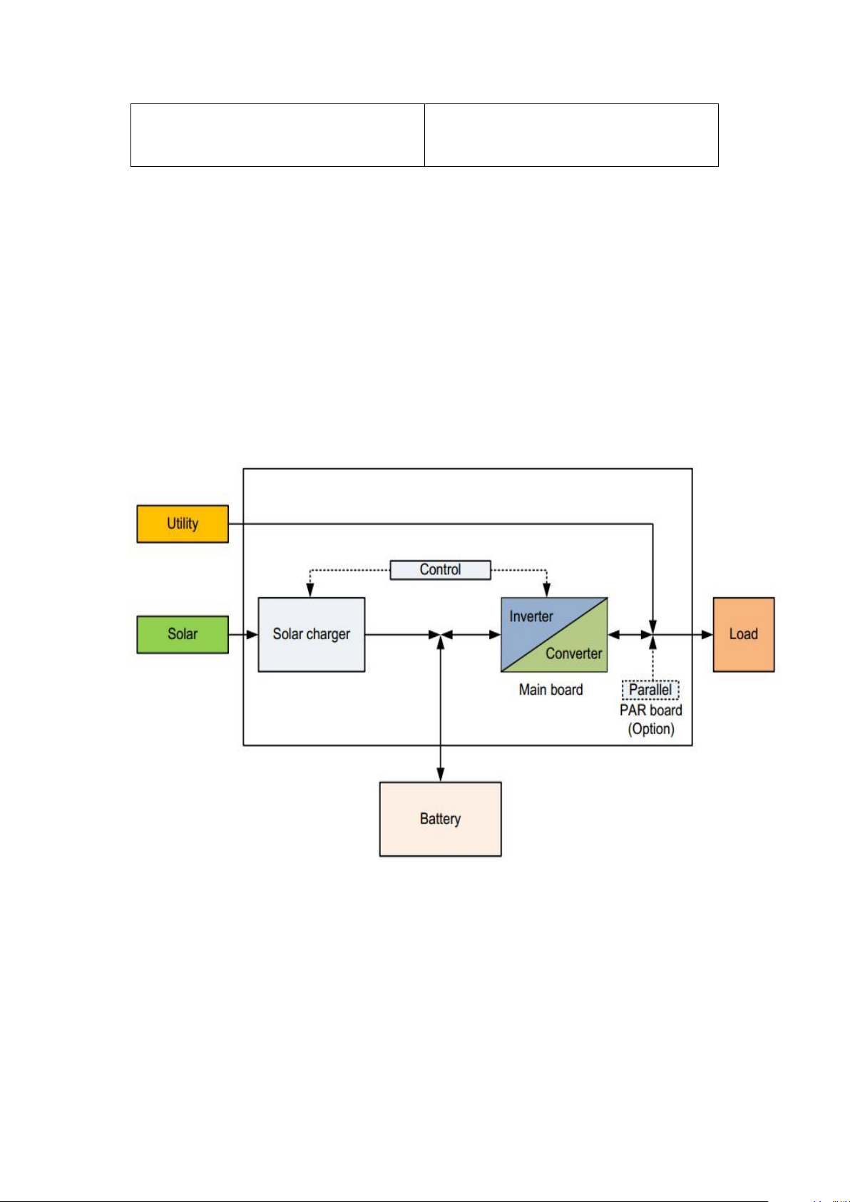
1.2 Basic Topology Introduction....................................................................................1
1.3 Overview of Inverter/Charger..................................................................................2
2. Fault and Troubleshooting.......................................................................................... 3
3. Steps to Repair .......................................................................................................... 4
3.1 Maintenance...........................................................................................................4
3.1.1 To Check DC FUSE and Capacitance............................................................4
3.1.2 DC/DC Boost Module.....................................................................................5
3.1.3 Divers.............................................................................................................6
3.2 To Check BUS Module............................................................................................9
3.2.1 Rectifier Diode................................................................................................9
3.3 To Check Full Bridge Invert Circuit........................................................................10
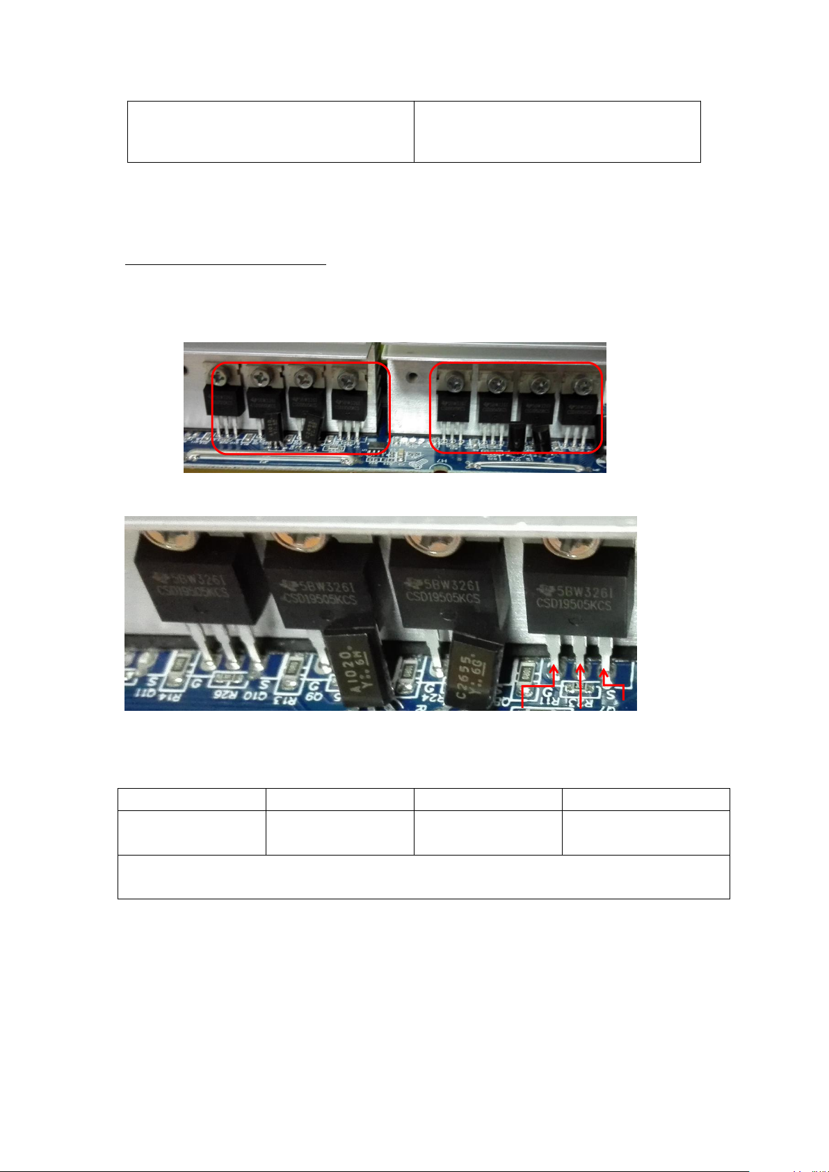
3.3.1 Power Devices...............................................................................................10
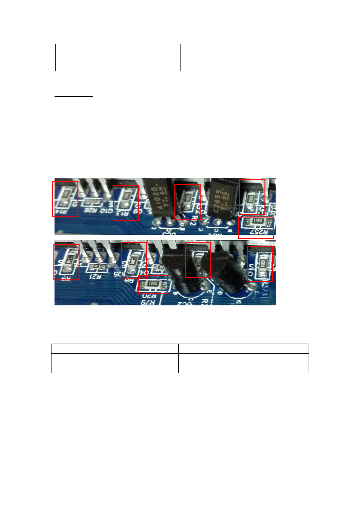
3.3.2 Divers.............................................................................................................10
3.3.3 To Check Drivers............................................................................................12
3.4 To Check AC Charging Circuit................................................................................13
3.4.1 To Inspect Power Components as.................................................................13
3.4.2 To Check Drivers............................................................................................13
3.5 To Check Rectifier Circuit.......................................................................................15
3.5.1 Charging Circuit.............................................................................................15
3.6 To Check Power Circuit.........................................................................................16
3.7 To Check MOSFETS for Reversed Protection on DC Terminal.............................19
3.8 To Check NTC Circuit.............................................................................................20
3.8.1 NTC in position of HS3 plugs in position of SW1 on main board..................20
3.8.2 NTC1 under Transformer...............................................................................20
3.8.3 NTC in HS4...................................................................................................21
3.9 To Check Fan Driver Circuit ..................................................................................22
4. Other Common Faulty Cases......................................................................................23
4.1 MOSFET Burnt.......................................................................................................23
4.2 Input Cable Disconnection......................................................................................23
4.3 Dust-covered Control Board...................................................................................24
5. Assembling Guidance..................................................................................................24
6. Test Guidance after Repairing.....................................................................................26
SUNRAELE Off-Grid Inv P 2-3kW
SUNRAELE

Service Manual
SUNRAELE Off-Grid Inv P 2-3kW
- 1 -
1. General Information
1.1 Brief Introduction
This manual is used as a tool of inspection and repairing guidance for
SUNRAELE Off-Grid Inv P 2-3kW, as well as instructions of assembling and
testing. It is best to have some electrical or electronic background knowledge.
With this guidance, hope it will help you to check and inspect the
inverter/charger first by yourself.
1.2 Basic Topology Introduction
The topology for 2KVA/3KVA shows as below:
SUNRAELE

Service Manual
SUNRAELE Off-Grid Inv P 2-3kW
- 2 -
1.3 Over review and Introduction of Inverter /charger Parts
Solar Charge Controller
& Control Board
Main Board
SUNRAELE

Service Manual
SUNRAELE Off-Grid Inv P 2-3kW
- 3 -
2. Fault and Troubleshooting
No LCD
display when
inverter turns
on
First to test battery volt to check whether it is in range of 44v-52v;
If it is in the range, to switch the inverter one to check whether the
unit starts. If the unit does not run yet, please disconnect all
connections and open the surface panel, take out the main board,
then to check and repair according to 3.7
01 First to replace the fan, to check whether it is okay; if NG, please
inspect the main board and repair according to 3.9
02 Please to check the main board and repair according to 3.8
03 Please to check first and then to repair the main board according
to 3.1, 3.6 and 3.7
06 First to start up the inverter by only connecting battery, if the fault
is still on, please inspect the main board following 3.3
08 To restart the inverter, to check whether the fault repeats, if yes, it
requires to replace the control boards.
09 To Check the main board following 3.1.2, 3.2.1, 3.4.1 and 3.5 and
to repair accordingly
52 First to restart inverter by only connecting to battery, if fault
continues, then to check the main board according to 3.1.2 and
3.4
56 First to check the connection of battery cable, if good connection,
then please to check and repair the main board following 3.1.1
and 3.1.2 accordingly
57 To replace the control board
58 First to restart inverter by connecting battery only, to check
whether it is good?
Second to connect battery and Utility but to keep switch off,
checking whether inverter charges battery? Otherwise, to check
and repair main board according to 3.1.2, 3.2.1 and 3.4.1
accordingly
72 To replace the control board
SUNRAELE

Service Manual
SUNRAELE Off-Grid Inv P 2-3kW
- 4 -
3. Steps to Repair
3.1 Battery Working Mode Test
3.1.1 To Check DC FUSE and Capacitance
F1-F6: 180-00001-00 (Fuse, F40A/32VDC UL)
Positioning
Attribute
Reference Value
Failure Status
F1-F6
Resistor
0 ohm
open
C19,C20,C39,C40: 140-00093-00 (Electrolytic Capacitor, 4200uF 35V M RAD 7.5mm
105℃)
SUNRAELE

Service Manual
SUNRAELE Off-Grid Inv P 2-3kW
- 5 -
D
G
S
If the capacitors explode, they need to be replaced.
3.1.2 DC/DC Boost Module
150-00052-00:MOSFET TI/CSD19505KCS 201A 80V N BULK TO-220
Positioning
Attribute
Reference Value
Failure Status
All MOSFET, 8pcs
Diode
SD:0.44V
DS:OL
Short-circuit
or Explosion
Note If one or more than one of them were broken, please replace all of them. For 2K, the
main board has just 6pcs MOSFETS.
SUNRAELE

Service Manual
SUNRAELE Off-Grid Inv P 2-3kW
- 6 -
3.1.3 Divers
Note: when there are power devices or components are damaged, Divers are
usually required to check.
The reference resistors listed as below.
R373,R7,R8,R9,R10,R11,R12,R13,R14,R79,R257
All the resistors are 100-10010-00 (RES CHIP TF 1/4W 10 F(1206))
To use Multi-meter to measure each resistors till to find out the broken ones
and to replace them, no need to change all the resistors.
Positioning
Attribute
Reference Value
Failure Status
All Resistors:
10 ohm
Resistor
22 ohm
Open Circuit
or other value
If resistors are need to replace, please check the diver transistors and
controlling IC.
SUNRAELE

Service Manual
SUNRAELE Off-Grid Inv P 2-3kW
- 7 -
UC2,UC4:150-00005-00 (Plug-in Transistor TOSHIBA/2SC2655-Y 2A 50V)
UC1,UC3:150-00004-00 (Plug-in Transistor TOSHIBA/2SA1020-Y 2A 50V)
UC4
UC1
UC3
E
C
UC2
B
SUNRAELE

Service Manual
SUNRAELE Off-Grid Inv P 2-3kW
- 8 -
Pin16
Pin9
Pin8
Pin1
Positioning
Attribute
Reference Value
Failure Status
UC2,UC4
Diode
BE:0.6V
BC:0.6V
CE:1V
Short-circuit or burnt
UC1,UC3
Diode
BE:0.6V
BC:1.3V
CE:0.2V
Short-circuit or burnt
U3: 160-00006-00 ( Plug-In : IC LINEAR FAIRCHILD/KA3525A)
Positioning
Attribute
Reference Value
Failure Status
U3
Diode
Pin11-Pin12:5.4M
Pin13-Pin12: 60K
Pin14-Pin12: 5.4M
Short Circuit or Burnt
If unable to make sure which components, we would like to suggest to replace them all.
Pin16
Pin9
Pin8
Pin1
SUNRAELE

Service Manual
SUNRAELE Off-Grid Inv P 2-3kW
- 9 -
Q28
3.2 To Check BUS Module
3.2.1 Rectifier Diode
Rectifier Diode: D17,D18,D19,D20
D17,D18,D19,D20: 150-10042-00 (FAIR./RHRP1560_NL 15A 600V)
Positioning
Attribute
Reference Value
Failure Status
D17,D18,D19,D20
Diode
+to-: 0.37V
-to+: OL
Short Circuit
or Broken
Note: If there is one or more than one components broken, please replace them all.
D18
+
-
D20
D19
D17
SUNRAELE

Service Manual
SUNRAELE Off-Grid Inv P 2-3kW
- 10 -
Q17
Q18
3.3 To Check Full-Bridge Invert Circuit
3.3.1 Power Parts
Q16,Q17,Q18,Q19:150-30088-00 (IGBT IR/IRGP4063D-EPBF 48A 600V TO-247)
Positioning
Attribute
Reference Value
Failure Status
Q16,Q17,Q18,Q19
Diode
EC: 0.4V
CE: OL
Short Circuit
or Broken
3.3.2 Divers
INV IGBT: Q16,Q17,Q18,Q19
Q16
Q17
Q18
Q19
G
C
E
SUNRAELE

Service Manual
SUNRAELE Off-Grid Inv P 2-3kW
- 11 -
R53,R55,R60,R63: 100-17047-00 (SMD Resistor CHIP TF 1/4W 4.7 F(1206))
R54,R56,R61,R64: 100-10100-00 (SMD Resistor CHIP TF 1/4W 100 F(1206))
ZD2,ZD3: 120-20072-00 (SMD Zen-er Diode PAN JIT 1SMA4745 16V 1W SMD)
D10,D12: 120-20007-00 (SMD Diode PANJIT/SS14 1A 40V SMD)
Positioning
Attribute
Reference Value
Failure Status
R53,R55,R60,R63
Resistor
4.7 ohm
Open Circuit or
other value
R54,R56,R61,R64
Resistor
100 ohm
ZD2,ZD3
Diode
+ to -: 0.6V
- to +: OL
Short Circuit
or Broken
D10,D12
Diode
+ to -: 0.6V
- to +: OL
ZD3
-
R54
D10
+
R55
R63
R53
R56
+
-
R60
D12
ZD3
R64
R61
SUNRAELE

Service Manual
SUNRAELE Off-Grid Inv P 2-3kW
- 12 -
3.3.3 To Check Drivers
U24,U25,U26,U27: 120-10065-00 (IC Driver Chip FOD3120 SMT)
Positioning
Attribute
Reference Value
Failure Status
U24,U25,U26,U27
Resistor
Pin8-Pin5: 2K
Pin7-Pin5:2K
Short Circuit
or Broken
C150/C151: 110-10040-00 ( SMD Capacitors CER MT 10nF 50V J NPO 103 (0805))
Positioning
Attribute
Reference Value
Failure Status
C150/C151
Capacitors
10nF
Short Circuit
or Broken
8
1
SUNRAELE

Service Manual
SUNRAELE Off-Grid Inv P 2-3kW
- 13 -
3.4 To Check AC Charging Circuit
3.4.1 To Check Power Components
Q20,Q21,Q22: 150-30032-00 ( Plug-in Transistor TSB/2SK3878 9A 900V N TUBE
TO-3PN)
Positioning
Attribute
Reference Value
Failure Status
Q20,Q21,Q22
Diode
EC: 0.4V
CE: OL
Short Circuit
or Broken
Note: If there is one or more than one components broken, please replace them all.
3.4.2 Drivers
R259,R261,R263: 100-10010-00 ( SMD Resistor CHIP TF 1/4W 10 F(1206))
R258,R260,R262: 100-10100-00 ( SMD Resistor CHIP TF 1/4W 100 F (1206))
D56/D57/D58: 120-20001-00 ( SMD Diode PANJIT/1N4148W 0.15A 75V SOD123)
Q20
C
Q22
G
Q21
E
SUNRAELE

Service Manual
SUNRAELE Off-Grid Inv P 2-3kW
- 14 -
Positioning
Attribute
Reference Value
Failure Status
R259,R261,R263
Resistor
10 ohm
Open Circuit or
other value
R258,R260,R262
Resistor
100 ohm
D56/D57/D58
Diode
EC: 0.6V
CE: OL
Short Circuit
or Broken
Note: When test diodes, please remove R259, R261, R263, otherwise the test result is not
right.
UC3843: U28
U28: 160-00001-00(Plug-in IC LINEAR ON/UC3843BNG)
Positioning
Attribute
Reference Value
Failure Status
U28
Resistor
Pin7-Pin5: 42K ; Pin6-Pin5: 30K
Short Circuit
or Broken
SUNRAELE

Service Manual
SUNRAELE Off-Grid Inv P 2-3kW
- 15 -
3.5 To Check Rectifier Circuit
3.5.1 Charging Circuit
D21/D22/D23: 150-10061-00 (Plug-in Diode ON/MBR20200CT 20A 200V SCKY RAD
BULK)
REC1: 150-10066-00 ( Plug-in Diode HY/GBU8M 8A1000V )
~
D22
D23
-
P
~
+
N
D22
D22
P
D22
D23
SUNRAELE

Service Manual
SUNRAELE Off-Grid Inv P 2-3kW
- 16 -
Positioning
Attribute
Reference Value
Failure Status
D21/D22/D23
Diode
P to N: 0.44V ; N to P: OL
Short Circuit
or Broken
REC1
Diode
~to +: 0.47V ; + to ~: OL
- to ~: 0.47; ~to -: OL
3.6 To Check Power Circuit
Q1: 150-30005-00 ( Plug-in Transistor MOSFET IR/IRF640NPBF18A 200V)
R1: 130-00211-00 ( Plug-in Resistor 3WS 0.15 J Rack F4)
U2: 120-10052-00 (IC PWM ON/UC3845BD1R2G L-1 SMD SOP-8)
SUNRAELE

Service Manual
SUNRAELE Off-Grid Inv P 2-3kW
- 17 -
CE6: 140-00044-00 (Electrolytic Capacitor 470uF35V M 5mm 105℃10*16mm Tape) If
the capacitor appears burst, please replace it.
R31: 100-17022-00 ( SMD Resistor CHIP TF 1/4W 2.2 F (1206) )
D1: 150-10009-00 (Plug-in Diode PAJIT/UF204 2A 400V ULTRAFAST AXI)
ZD4: 120-20072-00 ( SMD Zen-er Diode PAN JIT 1SMA4745 16V 1W SMD )
U11: 120-10037-00 (IC ON/MC78M05CDTG DPAK-3 SMD)
R94: 100-17047-00 ( SMD Resistor CHIP TF 1/4W 4.7 F (1206))
R90: 100-10020-00 (SMD Resistor CHIP TF 1/4W 20 F(1206))
ZD12: 120-00060-00 ( SMD Diode ON/1SMA5931BT3G DO214AC1.5W 18V SMD)
ZD12
G
I
R90
U11
R94
ZD4
U2
Q1
R31
1
S
D1
R1
G
8
D
CE6
O
SUNRAELE

Service Manual
SUNRAELE Off-Grid Inv P 2-3kW
- 18 -
R99: 100-30022-00 ( SMD Resistor CHIP TF 1W 2.2 F (0207) )
D34: 120-20048-00 (SMD Diode ON/MURA120T3 1A 200V 403D SMD)
Positioning
Attribute
Reference Value
Failure Status
Q1
Diode
SD: 0.5V ; DS: OL
Short Circuit
or Broken
D1
Diode
+ to -: 0.47V ; - to +: OL
ZD4
Diode
+ to -:0.4V ; - to +:OL
ZD12
Diode
+ to -:0.4V ; - to +: OL
D34
Diode
+ to -: 0.47V ; - to +: OL
U11
Resistor
I to O to G:OL
R99
Resistor
2.2omh
Open Circuit or
other Value
R1
Resistor
0.15omh
R31
Resistor
2.2omh
R94
Resistor
22 ohm
R90
Resistor
4.7omh
U2
Resistor
Pin7-Pin5:42K;Pin6-Pin5: 30K
Short Circuit
or Broken
SUNRAELE
Table of contents
Popular Inverter manuals by other brands

EmergoPlus
EmergoPlus PowerXtreme XS20 user manual

Projecta
Projecta IP3000 manual

Saurium
Saurium DLGE2500 Operating instruction

Sungrow
Sungrow SG250HX user manual

Dometic
Dometic PERFECTPOWER PP604 Installation and operating manual

SHENZHEN ENCOM ELECTRIC TECHNOLOGIES CO.
SHENZHEN ENCOM ELECTRIC TECHNOLOGIES CO. EN500 Series Service manual