SunSynk SSLB1 User manual
V7.0 – 03/22/2021
Power Lite Lithium Battery System
SSLB1
INSTALLATION MANUAL
Global Tech China Ltd, 3-Floor, Wai Yip Industrial Building.171 Wai Yip Street,
Kwun Tong, Kowloon, Hong Kong.
Tel: +852 2884 4318 Fax: +8522884 4816
www.sunsynk.com / sales@globaltech-china.com / www.globaltechhk.com

Index
1. INTRODUCTION ......................................................................................................................................... 4
2. SAFETY ...................................................................................................................................................... 5
2.1.
T
RANSPORTATION
.......................................................................................................................................... 5
2.2.
I
NSTALLATION
L
OCATION
................................................................................................................................. 5
2.3.
S
TORAGE
..................................................................................................................................................... 5
2.4.
G
ENERAL
S
AFETY
........................................................................................................................................... 5
2.5.
H
ANDLING
................................................................................................................................................... 6
2.6.
D
AMAGED
B
ATTERY
....................................................................................................................................... 6
2.7.
F
IRE
............................................................................................................................................................ 6
2.8.
Q
UALIFIED
P
ERSONNEL
................................................................................................................................... 6
3. SPECIFICATIONS AND FUNCTIONS ............................................................................................................. 7
3.1.
D
IMENSIONS AND
W
EIGH
................................................................................................................................ 7
3.2.
S
PECIFICATIONS
............................................................................................................................................. 8
3.3.
S
YSTEM
I
NTRODUCTION
.................................................................................................................................. 9
4. INSTALLATION ......................................................................................................................................... 10
4.1.
I
NSTALLATION
L
OCATION
E
NVIRONMENT
.......................................................................................................... 10
4.2.
F
RONT
V
IEW
............................................................................................................................................... 11
4.3.
R
ECOMMENDED
DC
B
REAKER
........................................................................................................................ 12
4.4.
DC
C
ABLE
R
EQUIREMENTS
............................................................................................................................. 12
4.5.
DC
C
ABLE
M
OUNTING
.................................................................................................................................. 12
4.5.1
M
ATERIAL
L
IST
.................................................................................................................................................. 12
4.5.2
S
TEPS
.............................................................................................................................................................. 12
4.6.
M
ASTER
-S
LAVE
C
ONFIGURATIONS
................................................................................................................... 13
4.6.1
S
INGLE
U
NIT
..................................................................................................................................................... 13
4.6.2
M
ULTI
-U
NITS
.................................................................................................................................................... 13
4.7.
C
OMMUNICATION
........................................................................................................................................ 16
4.7.1.
D
EFINITION OF
V
OLTAGE
S
AMPLING
C
ONNECTOR
................................................................................................... 16
4.7.2.
D
EFINITION OF
T
EMP
.
S
AMPLING
C
ONNECTOR
....................................................................................................... 16
4.7.3
P
ORT
RS485
AND
RS232 ................................................................................................................................... 17
5. BATTERY OPERATION AND COMMISSIONING ............................................................................................. 17
5.1.
S
YSTEM
P
OWER
ON ..................................................................................................................................... 17
5.2.
S
YSTEM
P
OWER
OFF .................................................................................................................................... 18
5.3.
S
LEEP AND WAKE UP FUNCTION
....................................................................................................................... 18
5.4.
B
UZZER FUNCTION
....................................................................................................................................... 18
5.5.
S
YSTEM
S
TATUS
I
NSTRUCTION
........................................................................................................................ 18
5.6.
LED
T
WINKLE
S
TATUS
.................................................................................................................................. 19

5.7.
S
O
C
INDICATOR
........................................................................................................................................... 19
6. MONITORING ............................................................................................................................................. 20
7. TROUBLESHOOTING ................................................................................................................................... 20
8. MAINTENANCE ........................................................................................................................................... 20
9. WARRANTY ................................................................................................................................................ 20
9.1.
W
ARRANTOR
.............................................................................................................................................. 20
9.2.
P
RODUCTS
................................................................................................................................................. 20
9.3.
P
RODUCT
W
ARRANTY
.................................................................................................................................. 21
9.4.
P
ERFORMANCE
W
ARRANTY
........................................................................................................................... 21
9.5.
W
ARRANTY
O
BLIGATIONS
............................................................................................................................. 21
9.6.
P
RODUCT
S
UITABILITY
.................................................................................................................................. 23
9.7.
W
ARRANTY
T
ERM
........................................................................................................................................ 23
9.8.
P
ERSONS
E
NTITLED TO
M
AKE
W
ARRANTY
C
LAIMS
.............................................................................................. 23
9.1.
C
LAIM
N
OTICE
............................................................................................................................................ 23
9.10.
W
ARRANTY
L
IMITATIONS
............................................................................................................................ 24
9.10.1.
E
XCLUDED
W
ARRANTY
C
LAIMS
......................................................................................................................... 24
9.10.2.
I
NTERNET
C
ONNECTIVITY
.................................................................................................................................. 24
9.11.
G
ENERAL
................................................................................................................................................. 25

Website: www.sunsynk.com E-mail: [email protected]
4
1. INTRODUCTION
Thank you for choosing Sunsynk’s energy storage system.
The energy storage module includes lithium-ion rechargeable batteries with 5.12kWh capacity, and the
controller enables a central of multiple modules.
This manual provides information regarding safety precautions to prevent possible accidents and how to
use the product. Please read this manual carefully before use for safety and keep this manual handy for
reference.
Some main features of this product are:
Long Life Span
The battery can be expected to remain serviceable for more than 10 years, considering that it is charged
and discharged once in a day at room temperature (25
°C
).
Stable
Olivine-type lithium iron phosphate batteries with excellent thermal stability and storage characteristics
are used in this product. The module also incorporates a self-monitoring function for the detection of any
abnormalities in energy storage.
Compact Design
The height is nicely designed in 3U, in favour of standard industrial applications.
High Scalability
Multiple energy storage modules can be connected in parallel, and the capacity can be customized
according to the intended use.
Website: www.sunsynk.com E-mail: [email protected]
5
2. SAFETY
Sunsynk's products are designed with full consideration of safety. However, all electrical appliances can
be dangerous if used inappropriately; it can cause a fire or electric shock that leads to severe injury or
death. For your protection, please read these safety precautions thoroughly.
2.1. Transportation
Lithium Ferro Phosphate Batteries are classed as Dangerous Goods (DG) Class 9 UN3480. It is forbidden
to subject the product to serious vibration and shock during transportation.
2.2. Installation Location
This battery set is to be installed only indoors.
The product should not be exposed the product to temperatures above or below the ambient
temperature rating specified in this manual.
The battery should not be installed in direct sunlight.
2.3. Storage
If the system is not placed to use, the system must be properly stored. Otherwise, Sunsynk shall not be
liable for any issues.
It should be stored in 60% SoC status.
It should be stored in a ventilated environment, Temp. < 35°C, RoH <65%.
It should be stored avoiding humid condition.
It should be stored in place where professionals can monitor by the system.
2.4. General Safety
Definitions of Symbols:
Below are symbols used in this manual and the unit.
Please read through the following definitions before reading the manual.
Warning If you ignore these instructions, it can lead to a fire or electric shock
causing serious injury or death.
Caution If you ignore these instructions, it can lead to electric shock or other
accidents causing injury or harm to nearby products.
Website: www.sunsynk.com E-mail: [email protected]
6
Wear insulating gloves and protection glasses during installation and connection of the set to prevent
electric shock or other injuries.
Water and/or foreign objects inside the module are not allowed.
The product should not be disassembled. Opening and modifying the set can cause a fire or electric
shock.
The cables should not be damaged. If you damage a cable, it can cause a fire or electric shock.
The battery should not be punch a hole in the product.
DO NOT touch with wet hands. If you touch the equipment with wet hands, it may cause electric shock.
The vent should not be covered. If the vent is covered, the product can overheat and cause a fire.
Keep the product away from children and animals.
DO NOT put anything, stand or sit on the battery set. If you put anything on the set, it may fall and
cause injury.
2.5. Handling
The battery should only be used as instructed.
DO NOT use the battery if it seems broken or damaged.
The battery is non-user-serviceable and should not be opened for repair.
Handle battery with care when installing or transporting.
Chemicals should not be used to clean the battery.
2.6. Damaged Battery
A damaged battery should not be used and should be returned to Sunsynk or properly discarded via a
recycling facility. Leaking electrolytes can cause skin irruption and chemical burns, so contact should be
avoided.
Eye Flush eyes with plenty of water for at least 15 minutes,
occasionally lifting the upper and lower eyelids. Get medical aid.
Skin Remove contaminated clothes and rinse skin with plenty of
water or shower for 15 minutes. Get medical aid.
Inhalation Remove from exposure and move to fresh air immediately. Use
oxygen if available.
Ingestion Give at least two glasses of milk or water. Induce vomiting
unless the patient is unconscious. Call a physician.
2.7. Fire
If the battery catches fire, a dry agent extinguisher must be available and used. DO NOT use water.
Evacuate the area and call emergency services. Toxic gas may be produced if the battery catches fire.
2.8. Qualified Personnel
Be aware that only qualified professionals should install the product.
Website: www.sunsynk.com E-mail: [email protected]
7
A qualified person is one who has skills and knowledge related to the construction and operation of the
electrical equipment and has received safety training on the hazards involved. It is authorized to energise,
ground, and tag equipment systems and circuits in accordance with established safety procedures. The
inverter and end-using system may only be commissioned by qualified personnel.
3. SPECIFICATIONS AND FUNCTIONS
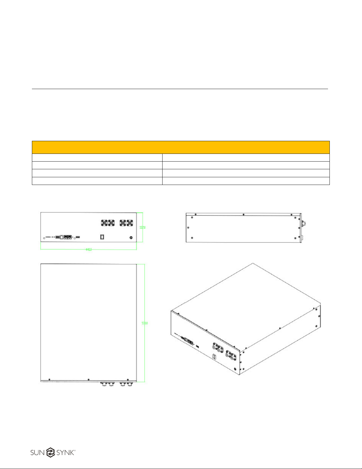
3.1. Dimensions and Weigh
SSLB1 dimensions are presented in Figure 1. It is well designed for 19-inch cabinet.
Power Lite Lithium Battery System SSLB1
Depth 530mm
Width 440mm
Height 132mm
Weight 48kg
Figure 1 - SSLB1 dimensions

Website: www.sunsynk.com E-mail: [email protected]
8
3.2. Specifications
Power Lite Lithium Battery System SSLB1
Cell Type Lithium Ferro Phosphate (LifePO4 or LFP)
Nominal Operating Voltage 51.2V
Nominal Capacity 100Ah / 5.12kWh
Rated DC Output Power 2.56kW
Depth of Discharge (DoD) 100%
Usable Capacity 5.12kWh
Packing 1P16S
IP Rating IP40
Minimum Operating Voltage 44.8V
Maximum Operating Voltage 57.6V
Standard Charging Current 50A
Max. Continuous Charging Current 50A
Standard Discharging Current 50A
Max. Continuous Discharging Current 100A (1C, 25°C ± 2°C)
Max. Pulse Discharging Current 200A(2C, 30S, 25°C ± 2°C SOC≥40%)
Max. DC Charge Power 2.56kW
Max. DC Discharge Power 5kW
Standard Charging Method 0.5C CC to 57.6V, CV at 57.6V till current is 0.05C
Min. Operating Temperature (no derating) Charging: 0°C / Discharging: -20°C
Max. Operating Temperature (no derating) Charging: 50°C / Discharging: 55°C
Operating ROH 20% ~ 80%
Storage Temperature -20 ~ 50°C
Self-discharging rate ≤5% (25°C, 50% SoC)
SoC @ end of product line 40%
Insulation Resistance >100MΩ
Voltage Difference in each module ≤20mV
Inner Resistance of single Cell 0.34 ± 0.05mΩ (fresh cell 30 ~ 40% SoC)
Altitude Below 2000m
Weight 48kg
Dimensions 440 x 530 x 132mm (not include connector,
MSD and
other parts)
Expected Life @ 25°C Greater than 10 years if used as per warranty terms
Website: www.sunsynk.com E-mail: [email protected]
9
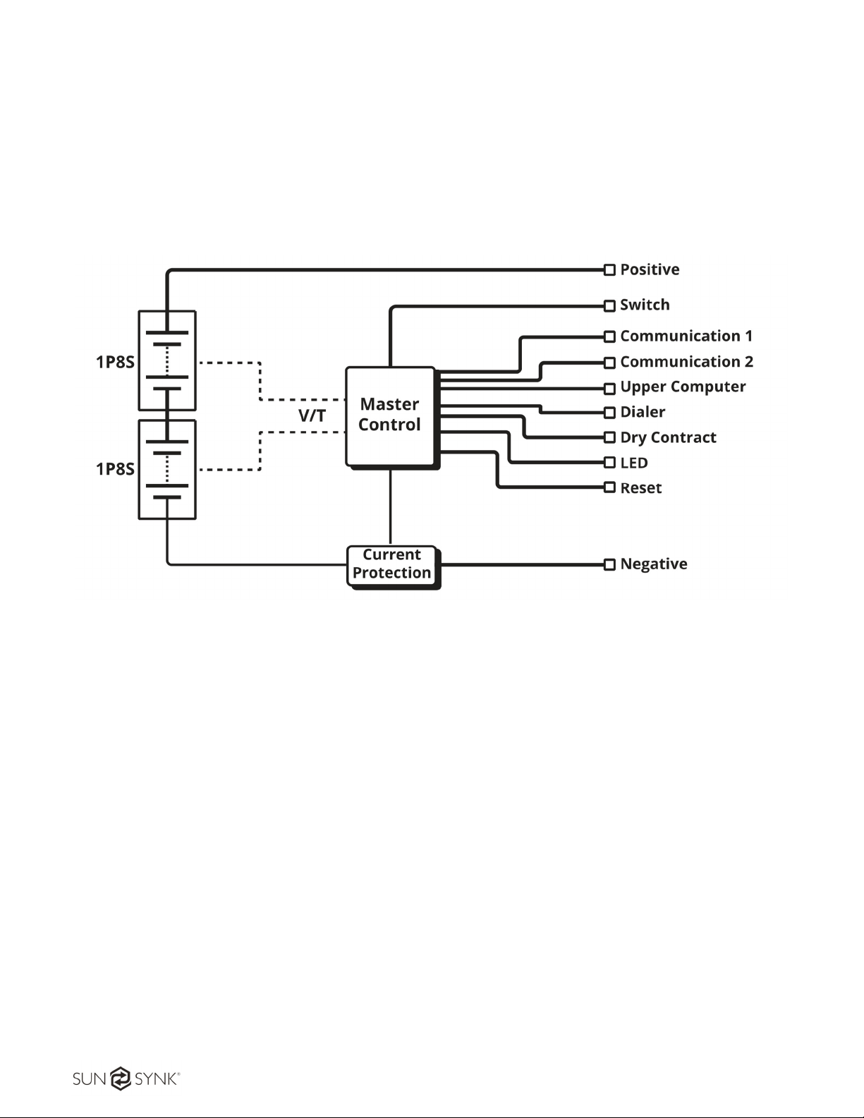
3.3. System Introduction
SSLB1 Energy Storage System is consisted of 2 sets of M025100-A modules manufactured by Sunsynk.
In each M025100-A, there are 8 pcs of 100 Ah LFP cell originated from CATL. The overall system also
provides standard communication port, i.e. CAN and RS485, to monitor the working status and
communicate with upper machine as well as the Power Conversion System (PCS) in front. The system
schematic drawing is presented in Figure 2.
Figure 2 - System schematics
The batteries are completely compatible with Sunsynk Hybrid Inverters listed below:
SUNSYNK-3.6K-SG01LP1 IP65
SUNSYNK-3.6K-SG02LP1 IP65
SUNSYNK-5.5K-SG01LP1 IP65
SUNSYNK-8.8K-SG02LP1 IP65
SUNSYNK-6K-SG02LP1
SUNSYNK-7.6K-SG02LP1
SUNSYNK-8K-3P-SG02LP1
SUNSYNK-10K-3P-SG02LP1
SUNSYNK-12K-3P-SG02LP1

Website: www.sunsynk.com E-mail: [email protected]
10
4. INSTALLATION
4.1. Installation Location Environment
The location of the battery should be in accordance with operating temperature range and IP rating
specified in the Specification section of this manual. Although the batteries run at a low temperature,
proper airflow around the batteries is recommended.
When installing the set, the following conditions should be met:
DO NOT install the product in a completely closed area with no air-conditioning, it can overheat and
cause a fire.
DO NOT place in direct sunlight or near a source of heat. This can cause deformation, a breakdown,
or a fire. Pay extra attention when you place the system near windows.
The battery must not be set where excessive oil smoke, steam, moisture or dust is contained in the
air.
Ensure that the batteries are installed in a clean environment with minimal dust.
Avoid installing the set near the ocean. If unavoidable, appropriate air filtration should be used to
prevent salt air in contact with the batteries.
For proper air circulation to dissipate heat, allow a clearance of approximately 30 cm to the sides of
the battery.
DO NOT install the set near heat sources.
Figure 3 – Minimum clearance.
Other manuals for SSLB1
2
Table of contents
Other SunSynk Camera Accessories manuals

SunSynk
SunSynk SUN-BATT-5.32R User manual

SunSynk
SunSynk SUN-BATT-5.12 Technical specifications

SunSynk
SunSynk L051100-A User manual

SunSynk
SunSynk SSLB1 User manual

SunSynk
SunSynk SSCLK3.1 User manual

SunSynk
SunSynk SUN-BATT-5.32R User manual

SunSynk
SunSynk SSLB1 User manual

SunSynk
SunSynk SUN-BATT-5.12R User manual

SunSynk
SunSynk SUN-BATT-5.12 User manual
Popular Camera Accessories manuals by other brands

Viltrox
Viltrox EF-NEX Mount instructions

Calumet
Calumet 7100 Series CK7114 operating instructions

Ropox
Ropox 4Single Series User manual and installation instructions

Cambo
Cambo Wide DS Digital Series Main operating instructions

Samsung
Samsung SHG-120 Specification sheet

Ryobi
Ryobi BPL-1820 Owner's operating manual


