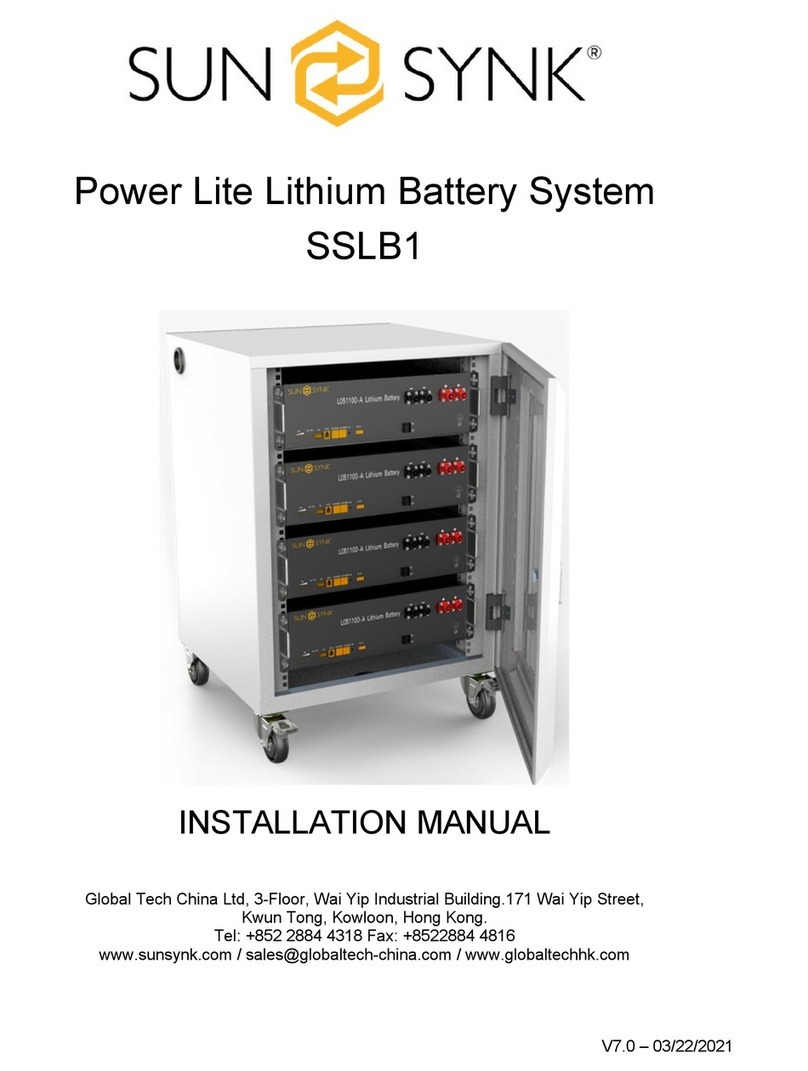
SunSynk SSLB1 User manual

SUNSYNK SSLB1 | Installation Manual1
INSTALLATION MANUAL
Global Tech China Ltd, 3 Floor, Wai Yip Industrial Building.
171 Wai Yip Street, Kwun Tong, Kowloon, Hong Kong.
Tel: +852 2884 4318 Fax: +8522884 4816
POWER LITE LITHIUM
BATTERY SYSTEM - SSLB1
v.10 (13/01/23)

SUNSYNK SSLB1 | Installation Manual2
Table of Contents
1. INTRODUCTION 4
2. SAFETY 5
2.1. Transportation 5
2.2. InstallationLocation 5
2.3. Storage 5
2.4. GeneralSafety 5
2.5. Handling 6
2.6. DamagedBattery 6
2.7. Fire 6
2.8. QualiedPersonnel 6
3. SPECIFICATIONSANDFUNCTIONS 7
3.1. DimensionsandWeigh 7
3.2. Specications 8
3.3. SystemIntroduction 8
4. INSTALLATION 10
4.1. InstallationLocationEnvironment 10
4.2. FrontView 11
4.3. RecommendedDCBreaker 11
4.4. DCCableRequirements 12
4.5. DCCableMounting 12
4.5.1. Material List 12
4.5.2. Steps 12
4.6. Master-SlaveCongurations 13
4.6.1. Single Unit 13
4.6.2. Multi-Units 13
4.7. Communication 15
4.7.1. Denition of Voltage Sampling Connector 15
4.7.2. Denition of Voltage Sampling Connector 16
4.7.3. Port CAN/RS485 and RS232 16
5. BATTERYOPERATIONANDCOMMISSIONING 17
5.1. SystemPowerON 17
5.2. SystemPowerOFF 17

SUNSYNK SSLB1 | Installation Manual3
5.3. SleepandWakeUpFunction 17
5.4. BuzzerFunction 17
5.5. SystemStatusInstruction 17
5.6. LEDTwinkleStatus 18
5.7. SoCIndicator 18
6. MONITORING 19
7. TROUBLESHOOTING 19
8. MAINTENANCE 19
9. WARRANTY 19
9.1. Warrantor 19
9.2. Warrantor 19
9.3. Warrantor 20
9.4. PerformanceWarranty 20
9.5. WarrantyObligations 20
9.6. ProductSuitability 21
9.7. WarrantyTerm 21
9.8. PersonsEntitledtoMakeWarrantyClaims 22
9.9. ClaimNotice 22
9.10. WarrantyLimitations 22
9.10.1. Excluded Warranty Claims 22
9.10.2. Internet Connectivity 23
9.11. General 23

SUNSYNK SSLB1 | Installation Manual4
Thank you for choosing Sunsynk’s energy storage system.
The energy storage module includes lithium-ion rechargeable batteries with 5.12kWh capacity, and the con-
troller enables a central of multiple modules.
This manual provides information regarding safety precautions to prevent possible accidents and how to use
the product. Please read this manual carefully before use for safety and keep this manual handy for refer-
ence.
Some prominent features of this product are:
LongLifeSpan
The battery can be expected to remain serviceable for more than 10 years, considering that it is charged
and discharged once a day at room temperature (25°C).
Stable
Olivine-type lithium iron phosphate batteries with excellent thermal stability and storage characteristics
are used in this product. The module also incorporates a self-monitoring function to detect any abnor-
malities in energy storage.
CompactDesign
The height is nicely designed in 3U, favoring standard industrial applications.
HighScalability
Multiple energy storage modules can be connected in parallel, and the capacity can be customized ac-
cording to the intended use.
1. INTRODUCTION

SUNSYNK SSLB1 | Installation Manual5
Lithium Ferro Phosphate Batteries are classed as Dangerous Goods (DG) Class 9 UN3480. It is forbidden to
subject the product to severe vibration and shock during transportation.
2. SAFETY
Sunsynk's products are designed with full consideration for safety. However, all electrical appliances can be
dangerous if misused; they can cause a re or electric shock, leading to severe injury or death. For your
protection, please read these safety precautions thoroughly.
2.1. Transportation
2.2. Installation Location
2.3. Storage
This battery set is to be installed only indoors.
The product should not be exposed to temperatures above or below the ambient temperature rating
specied in this manual.
The battery should not be installed in direct sunlight.
If the system is not placed to use, the system must be stored appropriately. Otherwise, Sunsynk shall not be
liable for any issues.
It should be stored in 60% SoC status.
It should be stored in a ventilated environment, Temp. < 35°C, RoH <65%.
It should be stored in low-humid ambients.
It should be stored where professionals can monitor it using the monitor system.
2.4. GeneralSafety
DenitionsofSymbols:
Below are symbols used in this manual and the unit.
Please read through the following denitions before reading the manual.
WARNING Ignoring these instructions can lead to a re or electric shock, causing severe
injury or death.
CAUTION Ignoring these instructions can lead to electric shock or other accidents,
causing injury or harm to nearby products.
Wear insulating gloves and protection glasses during installation and connection of the set to prevent
electric shock or other injuries.
Water and/or foreign objects inside the module are not allowed.
The product should not be disassembled. Opening and modifying the set can cause a re or electric
shock.
The cables should not be damaged. If you damage a cable, it can cause a re or electric shock.

SUNSYNK SSLB1 | Installation Manual6
2.5. Handling
The battery should only be used as instructed.
DO NOT use the battery if it seems broken or damaged.
The battery is non-user-serviceable and should not be opened for repair.
Handle the battery with care when installing or transporting it.
Chemicals should not be used to clean the battery.
2.6. DamagedBattery
A damaged battery should not be used and should be returned to Sunsynk or properly discarded via a
recycling facility. Leaking electrolytes can cause skin irruption and chemical burns, so contact should be
avoided.
Eye Flush eyes with plenty of water for at least 15 minutes, occasionally lifting the upper and
lower eyelids. Get medical aid.
Skin Remove contaminated clothes and rinse skin with plenty of water or shower for 15 min-
utes. Get medical aid.
Inhalation Remove from exposure and move to fresh air immediately. Use oxygen if available.
Ingestion Give at least two glasses of milk or water. Induce vomiting unless the patient is uncon-
scious. Call a physician.
The battery should not be punched. DO NOT punch the product
DO NOT touch with wet hands. If you touch the equipment with wet hands, it may cause an electric
shock.
The vent should not be covered. If the vent is covered, the product can overheat and cause a re.
Keep the product away from children and animals.
DO NOT put anything, stand or sit on the battery set. If you put anything on the set, it may fall and cause
injury.
2.7. Fire
A dry agent extinguisher must be available and used if the battery catches re. DO NOT use water. Evacuate
the area and call emergency services. Toxic gas may be produced if the battery catches re.
2.8. QualiedPersonnel
Be aware that only qualied professionals should install the product.
A qualied person is one who has skills and knowledge related to the construction and operation of electri-
cal equipment and has received safety training on the hazards involved. It is authorized to energize, ground,
and tag equipment systems and circuits in accordance with established safety procedures. The inverter and
end-using system may only be commissioned by qualied personnel.

SUNSYNK SSLB1 | Installation Manual7
3. SPECIFICATIONSANDFUNCTIONS
3.1. Dimensions and Weigh
SSLB1 dimensions are presented below. It is well designed for 19-inch cabinet.
PowerLiteLithiumBatterySystemSSLB1
Depth 530mm
Width 440mm
Height 132mm
Weight 48kg

SUNSYNK SSLB1 | Installation Manual8
3.2. Specications
PowerLiteLithiumBatterySystemSSLB1
Cell Type Lithium Ferro Phosphate (LifePO4 or LFP)
Nominal Operating Voltage 51.2V
Nominal Capacity 100Ah / 5.12kWh
Rated DC Output Power 2.56kW
Depth of Discharge (DoD) 100%
Usable Capacity 5.12kWh
Packing 1P16S
IP Rating IP40
Minimum Operating Voltage 44.8V
Maximum Operating Voltage 57.6V
Standard Charging Current 50A
Max. Continuous Charging Current 50A
Standard Discharging Current 50A
Max. Continuous Discharging Current 100A (1C, 25°C ± 2°C)
Max. Pulse Discharging Current 200A (2C, 30S, 25°C ± 2°C SoC≥40%)
Max. DC Charge Power 2.56kW
Max. DC Discharge Power 5kW
Standard Charging Method 0.5C CC to 57.6V, CV at 57.6V till current is 0.05C
Min. Operating Temperature (no derating) Charging: 0°C / Discharging: -20°C
Max. Operating Temperature (no derating) Charging: 50°C / Discharging: 55°C
Operating ROH 20% ~ 80%
Storage Temperature -20 ~ 50°C
Self-discharging rate ≤5% (25°C, 50% SoC)
SoC @ the end of the product life 40%
Insulation Resistance >100MΩ
Voltage Dierence in each module ≤20mV
Inner Resistance of a single Cell 0.34 ± 0.05mΩ (fresh cell 30 ~ 40% SoC)
Altitude Below 2000m
Weight 48kg
Dimensions 440 x 530 x 132mm (not include connector, MSD
and other parts)
Expected Life @ 25°C Greater than 10 years if used as per warranty terms
3.3. SystemIntroduction
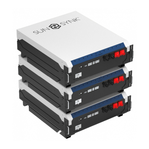
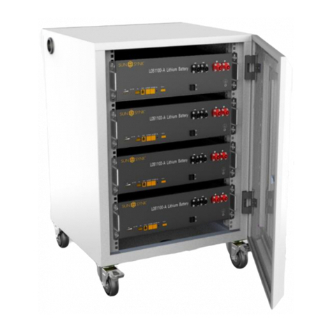
SSLB1 Energy Storage System consists of 2 sets of M025100-A modules manufactured by Sunsynk. In each
M025100-A, there are 8 pcs of 100 Ah LFP cells originating from CATL. The overall system also provides a
standard communication port, i.e., CAN and RS485, to monitor the working status and communicate with the
upper machine and the Power Conversion System (PCS) in front. The system schematic drawing is presented
below.
SUNSYNK SSLB1 | Installation Manual9
The batteries are completely compatible with Sunsynk Hybrid Inverters listed below:
SUNSYNK-3.6K-SG01LP1 IP65
SUNSYNK-3.6K-SG02LP1 IP65
SUNSYNK-5.5K-SG01LP1 IP65
SUNSYNK-8.8K-SG02LP1 IP65
SUNSYNK-6K-SG02LP1
SUNSYNK-7.6K-SG02LP1
SUNSYNK-8K-3P-SG02LP1
SUNSYNK-10K-3P-SG02LP1
SUNSYNK-12K-3P-SG02LP1

SUNSYNK SSLB1 | Installation Manual10
4. INSTALLATION
4.1. Installation Location Environment
The location of the battery should be in accordance with the operating temperature range and IP rating
specied in the Specication section of this manual. Although the batteries run at a low temperature, proper
airow around the batteries is recommended.
When installing the set, the following conditions should be met:
Please DO NOT install the product in a completely closed area with no air-conditioning. It can overheat
and cause a re.
DO NOT place in direct sunlight or near a source of heat. This can cause deformation, a breakdown, or a
re. Pay extra attention when you place the system near windows.
The battery should not be set where excessive oil smoke, steam, moisture or dust is contained in the air.
Ensure that the batteries are installed in a clean environment with minimal dust.
Avoid installing the set near the ocean. If unavoidable, appropriate air ltration should be used to
prevent salt air in contact with the batteries.
For proper air circulation to dissipate heat, allow a clearance of approximately 30 cm to the sides of the
battery.
DO NOT install the set near heat sources.
If the batteries are being installed in areas of extreme humidity levels, take the following precautions:
A humidity control agent must be placed inside the enclosure, with controlled airow to expel moist air,
and/or the system can be installed in a proper room with humidity control.
The SSLB1 battery is well-designed to be installed in a 19-inch cabinet. A suitable IP54 or above enclosure
must be used if the battery is installed outdoors.

SUNSYNK SSLB1 | Installation Manual11
Please refer to AS/NZS 5139 for the installation requirements in Australia. This product can be installed
under Section 5 of AS/NZS 5139 for Preassembled BS products.
4.2. FrontView
Item Name Model Remarks
1 SOC LED x4
2 Alarm LED
3 RUN LED
4 Dialer
5 Communication port RJ11 RS232 To upper machine
6 Communication port *2 RJ45 CAN To PCS RS485 Internal Connection
7 Reset Waken system from malfunction status
8 Dry Contact
9 Power On/O Switch
10 Port Negative x2 PSR6XAB Black 5.7, 25mm2
11 Port Positive x2 PSR6XBB Orange 5.7, 25mm2
12 GND M6 Yellow-Green, 10AWG
4.3. Recommended DC Breaker
An overcurrent protection and isolation device between the battery and inverter. The following circuit
breaker models (purchased separately) are supported:
CircuitBreakerModel Rating Certicate
Nader NDB1-125 100 A CCC, CE, CB, TUV, UL1077
NOTE: The circuit breaker should operate positive and negative conductors simultaneously.

SUNSYNK SSLB1 | Installation Manual12
4.4. DC Cable Requirements
Size OuterDiameter Max.Voltage Max.Current
21-33 mm² 10-12 mm 1000 V 120 A
CAUTION
DC cable must be a multicore wire.
4.5. DC Cable Mounting
CAUTION
Turn o the system before making electrical connections.
Ensure all the cables are in safe electrical conditions.
4.5.1. Material List
Plug IsolationCap Tail-hood
4.5.2. Steps
1. Put the wire through the isolation cap and Tail-Hood.
2. Swipe the outer isolation layer of the DC cable.

SUNSYNK SSLB1 | Installation Manual13
3. The red is used for the positive and the negative for the black contact. The end of the cable is bunched
at the terminal using a wire clamp.
4. Tighten the isolation cap and plug the contact.
5. Put the positive and negative plugs onto the system and tighten it.
6. Use an isolation cap for unused DC plugs.
4.6. Master-SlaveCongurations
The Master Pack and The Slave Pack, both with the same model (SSLB1), can be used as a single unit and in
multi-units (in parallel) mode. The customers must inform the supplier if they intend to connect more batter-
ies (multi-units mode), so one can double-check master-slave settings because the DIP address conguration
is dierent if the number of batteries in parallel changes. The Master Pack can be used individually, but Slave
Pack cannot be used separately. Each battery can be set as the master or the slave by changing the DIP ad-
dress conguration. Please refer to the attached best practice guidance document.
4.6.1. Single Unit
If you use only a single battery, it is only necessary to connect the positive and negative cables.
4.6.2. Multi-Units
You can add more batteries in parallel to increase the storage capacity. However, no cabinets or racks are
supplied with the battery.
In order to connect multi-units, some steps need to be followed. In this example, it is considered that the
user will connect up to four batteries.

SUNSYNK SSLB1 | Installation Manual14
1. Connect all positive terminals.
2. Connect all negative terminals.
3. Connect all the batteries to the same grounding point.
4. In order to set the master and slaves, it is necessary to set up the DIP switches (ON or OFF).
5. Follow the settings presented below to set the desired conguration.

SUNSYNK SSLB1 | Installation Manual15
6. It is also necessary to connect the CAN/RS485 cables between the units.
4.7. Communication
4.7.1. DenitionofVoltageSamplingConnector
PIN WireNo. Signal Wiresize(mm²) Remarks
1 B0 Signal 0.3 Cell #1-
2 B2+ Signal 0.3 Cell #2+
3 B4+ Signal 0.3 Cell #4+
4 B6+ Signal 0.3 Cell #6+
5 B8+ Signal 0.3 Cell #8+
6 B10+ Signal 0.3 Cell #10+
7 B12+ Signal 0.3 Cell #12+
8 B14+ Signal 0.3 Cell #14+
9 B16+ Signal 0.3 Cell #16+

SUNSYNK SSLB1 | Installation Manual16
PIN WireNo. Signal Wiresize(mm²) Remarks
10 NC NC NC NC
11 B1+ Signal 0.3 Cell #1+
12 B3+ Signal 0.3 Cell #3+
13 B5+ Signal 0.3 Cell #5+
14 B7+ Signal 0.3 Cell #7+
15 B9+ Signal 0.3 Cell #9+
16 B11+ Signal 0.3 Cell #11+
17 B13+ Signal 0.3 Cell #13+
18 B15+ Signal 0.3 Cell #15+
4.7.2. DenitionofVoltageSamplingConnector
PIN WireNo. Signal Wiresize(mm²) Remarks
1 T1+ Signal 0.3 Temp. #1+
2 T2+ Signal 0.3 Temp. #2+
3 T3+ Signal 0.3 Temp. #3+
4 T4+ Signal 0.3 Temp. #4+
5 T1- Signal 0.3 Temp. #1-
6 T2- Signal 0.3 Temp. #2-
7 T3- Signal 0.3 Temp. #3-
8 T4- Signal 0.3 Temp. #4-
4.7.3. PortCAN/RS485andRS232
Description - Battery Side Description - Inverter Side
CAN
Pin 1: CAN-H
Pin 5: CAN-L
Pin 2, 3, 4, 6, 7, 8: NC
Pin 4: CAN-H
Pin 5: CAN-L
Pin 1, 2, 3, 6, 7, 8: NC
RS485
Pin 1: RS485B
Pin 2: RS485A
Pin 3: GND
Pin 6: GND
Pin 7: RS485B
Pin 8: RS485A
Pin 4, 5: NC
Pin 1: RS485B
Pin 2: RS485A
Pin 3: GND
Pin 6: GND
Pin 7: RS485B
Pin 8: RS485A
Pin 4, 5: NC
RS232
Pin 3: BMS transmit; Computer receiver
Pin 4: BMS receiver; Computer transmit
Pin 5: GND
Pin 1, 2, 6: NC
Pin 3: BMS transmit; Computer receiver
Pin 4: BMS receiver; Computer transmit
Pin 5: GND
Pin 1, 2, 6: NC
The following table shows the connection for the
batterysideandinverterside.

SUNSYNK SSLB1 | Installation Manual17
5. BATTERYOPERATIONANDCOMMISSIONING
Before turning on the batteries, please check the installation:
Check the polarities of the batteries.
Check if there are no damaged cables.
Check for local installation compliance.
Check if proper airow is provided to the set.
5.1. SystemPowerON
Installation (including DC cable, communication wire connection, dialer switch, and circuit breaker) is
appropriately down.
Press the Power Switch button and then the external circuit breaker. The green LED should be twinkling
and then turn into function mode. (system status can be read from the LED signal, as shown below).
5.2. SystemPowerOFF
Attention:ItmustbeconrmedthatthesystemisobeforetakingotheDCcables.
Press the Power Switch button.
Green LED should be twinkling and then turn into stop mode.
5.3. SleepandWakeUpFunction
Number SleepCondition WakeUpCondition Mark
1 Forced sleep by upper computer Reset button
2 Forced sleep by soft switch Soft switch,
Only those equipped
with soft switch can pass
the call Wake Up
3
Total Voltage is lower than 48V
or monomer is lower than 2.8V,
and continuous No charge and
discharge current for 4 hours, no
communication goes to sleep
Reset button,
Soft switch,
Communication,
Charging
Only those equipped
with soft switch can pass
the call Wake Up
5.4. BuzzerFunction
0.25s per 1s in case of fault.
0.25s per 2S during protection.
5.5. SystemStatusInstruction
There are 6 LED indicators, 4 green LEDs that present the status of the SoC, 1 red Alarm LED and 1 green
Running Status LED (indicating charging, discharging etc.).

SUNSYNK SSLB1 | Installation Manual18
5.6. LEDTwinkleStatus
Status On O
Twinkle 1 0.25s 3.75s
Twinkle 2 0.5s 0.5s
Twinkle 3 0.5s 1.5s
5.7. SoC Indicator
SoC
LED
LED1 LED2 LED3 LED4
0~25% On O O O
25%~50% On On O O
50%~75% On On On O
75%~100% On On On On

SUNSYNK SSLB1 | Installation Manual19
6. MONITORING
The battery does not include a monitoring system. However, the user can utilise the inverter’s remote
monitoring app.
7. TROUBLESHOOTING
The Power Lite SSLB1 battery set is designed to run with most systems as a lead-acid replacement energy
storage solution. Lithium batteries have a much higher density related to lead-acid batteries, and they utilise
the settings and protections built into the ancillary equipment, the BMS.
When the battery operation is outside limits, the BMS activates to provide safe operation.
During normal operation, there will be a voltage across the terminals of the batteries. If the BMS activates
its protection circuit, the battery should restart without external assistance once the fault is cleared. The
scenario where this may not occur is on low volt disconnect. In this case, the battery circuit breaker will need
to be turned o and on again to restart the BMS.
In rare cases where the voltage does not recover, it is necessary to apply an external power source to the
battery output terminal, allowing the battery to charge up above the BMS low voltage cut-o. Once the
voltage rises above this point, the BMS will make the battery operate normally.
8. MAINTENANCE
The Power Lite SSLB1 is maintenance-free. However, some verications can be conducted as part of your
overall system maintenance.
Check LED indicators.
Check for any obstruction placed around the battery.
Check battery connections and cables for secure tting or damage.
Check circuit breakers by turning them o and on again.
9. WARRANTY
Warrantor is SunsynkLtd, located at 3-Floor,WaiYipIndustrialBuilding,171WaiYipStreet,Kwun
Tong,Kowloon,HongKongS.A.R.
9.1. Warrantor
9.2. Warrantor
The following limited warranty terms and conditions (‘Factory Warranty’) apply exclusively to SunsynkLtd’s
products of the following types (‘Covered Products’):
PowerLiteLithiumBatterySystemSSLB1
ValidDatefrom:
which:
were manufactured by and bear the original manufacturing label of SunsynkLtd.

SUNSYNK SSLB1 | Installation Manual20
were sold by SunsynkLtd directly or through a certied SunsynkLtd dealer (‘Authorised Dealer’) as new
products in the world.
were installed and commissioned by an Authorised, Certied Dealer in the world.
9.3. Warrantor
For Covered Products, SunsynkLtd covers all defects in workmanship and materials during the Warranty
Period under normal application, installation, use and service conditions as specied in SunsynkLtd’s
standard product documentation, and subject to the conditions listed below (‘Product Warranty’). The
Product Warranty is not intended to be a durability warranty, as end-user conditions and usage are variable.
SunsynkLtd specically disclaims any warranty to include specic components in any product or service.
Our goods come with guarantees that cannot be excluded under the Australian Consumer Law. You are en-
titled to a replacement or refund for a major failure and compensation for any other reasonably foreseeable
loss or damage. You are also entitled to have the goods repaired or replaced if the goods fail to be of accept-
able quality, and the failure does not amount to a major failure.
9.4. PerformanceWarranty
Sunsynk Ltd guarantees that the actual storing capacity of the original battery pack included in the Covered
Product (‘Power Lite SSLB1’) will be not less than 70% of the labelled storing capacity.
9.5. WarrantyObligations
a. During the Warranty Period,SunsynkLtd will, at its option, repair the defective parts (if economically
easible) or replace the defective part free of charge, provided that you properly notify SunsynkLtd of
the product defect within the Warranty Period and provide that SunsynkLtd, through inspection,
establishes the existence of a defect covered by this Limited Warranty.
b. SunsynkLtd will, at its option, use new and/or reconditioned parts in building replacement parts.
SunsynkLtd reserves the right to use parts or products of an original or improved design to repair or
replace your product. If SunsynkLtd repairs or replaces a product part, its warranty continues for the
remaining portion of the Warranty Period or 90 days from the date of the repair or replacement,
whichever is greater.
c. This Factory Warranty covers SunsynkLtd costs for materials necessary to re-establish the trouble-free
operation of the Covered Product. This Factory Warranty does NOT cover, however, costs of installation,
cost of removal, cost of labour for repair, cost of shipping or cost of reinstallation of a Covered Product
or parts thereof.
d. In the event of a defect of products or services supplied by SunsynkLtd, Customer’s sole remedy shall
be, at SunsynkLtd’s cost and expense up to 100% of the cost of the equipment, (a) repair or
replacement of the defective product at SunsynkLtd’s discretion, or (b) re-performance of defective
services.
e. Except for visible defects of products and services for which Customer shall provide notice to Sunsynk
Ltd immediately under Section 6.3 of SunsynkLtd’s Terms & Conditions. The Customer shall provide
written notice of any defect to Sunsynk Ltd within 10 days after discovering the defect.
f. Should SunsynkLtd be unable to repair or replace defective products or re-perform defective services
Other manuals for SSLB1
2
Table of contents
Other SunSynk Camera Accessories manuals

SunSynk
SunSynk SUN-BATT-5.12 User manual

SunSynk
SunSynk SSCLK3.1 User manual

SunSynk
SunSynk L051100-A User manual

SunSynk
SunSynk SUN-BATT-5.32R User manual

SunSynk
SunSynk SUN-BATT-5.12R User manual

SunSynk
SunSynk SUN-BATT-5.32R User manual

SunSynk
SunSynk SSLB1 User manual

SunSynk
SunSynk SUN-BATT-5.12 Technical specifications

SunSynk
SunSynk SSLB1 User manual