GivEnergy 3HY 6.0 User manual

INSTALLATION MANUAL
GENERATION 3 | 3-PHASE + STACKABLE BATTERY
3HY 6.0, 3HY 8.0, 3HY 10.0, 3HY 11.0
10.2 HV, 13.6 HV, 17.0 HV, 20.4 HV
V 1.0 09/23

SPECIFICATIONS
Specications
The 3-phase GivEnergy Hybrid Inverter is a battery
inverter and solar inverter in one unit, meaning
that the battery is AC and DC coupled.
It can be coupled directly with solar panels to
generate usable electricity in the property, as well
as store any excess energy in the battery for later
use. It features easy plug and play installation and
on / o grid phase balancing. Additionally , it will
minimise import by discharging to meet demand in
the property with a discharge rate of up to 11kW.
The unit can also be used as an AC coupled
alongside existing solar installations.
Hybrid Inverter
A TRUE MULTITASKER
Dimensions
658H x 214D x 480W (mm)
Warranty
12 years
Weight
35 Kg
Operational temperature
-25ºC - 60ºC (derating at 50ºC)
Charge / Discharge Eciency
97.6% / 96%
Start Up Voltage
200V
PV Max. Eciency
97.9%
Max. DC Input Power
6.0kW
8.0kW
10.0kW
11.0k W
-
-
-
-
9kW
12kW
15k W
15k W
PREPARATION
Item Item Name
Drill
Wire cutters
A
F
Suitable drill bit for wall and xings
Wire strippers
Pen/pencil
B
G
K
C
H
L
Set of Allen keys
Crimping tool
RJ45 crimping tool (for making own LAN cable)
D
I
M
E
J
N
O
Multimeter
Socket set for wall bolts
USB stick (for updating rmware)
Knife
Tape measure and spirit level
Laptop/tablet/phone with internet connection for commissioning
Insulated screw drivers
Before installation, the following tools are required:
Note: Please adhere to best practices and local legislation for manual handling processes when moving,
lifting and installing the equipment.

C
BOX CONTENTS
Item Item Name Qty
InverterA1
Wall Mounting BracketB1
CBolt to Secure Inverter to Mounting Bracket 2
DMounting Bracket Fixings 5
A
D
B
Introduction
Installation Requirements
Installation of all GivEnergy equipment must be carried out by a GivEnergy Approved Installer.
Please ensure that there is sucient space and ventilation around the inverter and battery before
installation.
Unit Information
The 3-Phase Hybrid Inverter is a battery inverter and PV inverter in one. It is bi-directional, meaning it
can charge from the grid (AC coupled) and from solar (DC coupled). It can also charge from existing solar
installations.
Storing the Inverter
The unit must be stored in its original packaging at temperatures between 25ºC - 60ºC.
Do not stack more than 4 units on top of each other.
If any damaged or missing parts are found, please contact GivEnergy on 01377 252 874 or email
support@givenergy.co.uk immediately. Returns must be provided in original or equivalent packaging. The
cardboard packaging is recyclable.
Packaging Contents
All information contained in this booklet refers to the assembly, installation, commissioning, and
maintenance of the 3-Phase Hybrid Inverter. Please retain this manual for future reference.
When unpacking, please check the following:
• There are no missing accessories from the packaging list
• The model and specication of the inverter’s nameplate match the order specications
GENERAL INFORMATION
Legal Disclaimer: This document is the property of GivEnergy, reproduction is prohibited.

Item Item Name
Power Flow Direction IndicatorsA
Battery connection pointB
PV Input SwitchC
DPV Input Terminals
E4G Module USB Port (Optional)
FCommunication Ports
GAC Supply Terminals (Right) and EPS Terminals (Left)
H
J
Serial No.
Warning Signs Label
I
K
L
WiFi Serial No. and Verication Code
Specication Label
Heat Sink
SYSTEM APPEARANCE
A
B
C
D
E
F
G H
I
J
L
K
Do not install in direct sunlight or near water sources
Mount the inverter at least 3 feet above ground level (outside only)
The inverter must be installed in an easily accessible location, the status display
must be visible and not obstructed
Please ensure that the wall to be mounted on is sucient enough to hold the weight
of the inverter and battery pack
The inverter must be installed in a well ventilated area with 30cm clearance
around it, free of any obstacles. The ambient temperature should be below 40ºC
to ensure optimal operation
The inverter must be installed vertically with connections always positioned at the
bottom, never install horizontally, and avoid tilting the unit
Extra care and attention must be taken when installing and maintaining any GivEnergy equipment.
The system is capable of retaining a high voltage, even when disconnected.
Safety Instructions
SAFETY AND INSTALLATION
All electrical installations must be carried out by a qualied and registered electrician and in accordance
with local wiring regulations
During operation, the heat sink may become hot. Do not touch the heat sink at the sides, or the top
of the inverter when in operation
The inverter is designed to be connected to the grid; connecting your inverter to a generator or
other power source can result in damage to the inverter or external devices
All GivEnergy equipment must be installed by a GivEnergy Approved Installer
If there are any damaged or missing parts, please contact the distributor immediately. Returns must be
provided in original or equivalent packaging
If you suspect something is wrong with the inverter, contact GivEnergy on 01377 252 874 or email
support@givenergy.co.uk

Precautions
Only GivEnergy supplied battery cables must be used
Only GivEnergy batteries should be connected to our inverters
Reversed polarity may damage the inverter
Please ensure that there is sucient space and ventilation around the inverter and battery before
installation.
The bracket is attached to the inverter when in the box. Take o the 2 bolts at the bottom to remove
the bracket.
Wall thickness should be suitable to hold the weight of the inverter. Place the wall mounting bracket
horizontally onto the wall and mark the position for the bracket holes.
Note: Take into consideration that batteries may be added at a later date. To allow for this, hang
the inverter higher to ensure there is enough space.
If installing the products outside: make sure the products are not in direct sunlight, and are
situated in a location where the inverter remains within operating temperatures. This is to ensure
the unit remains fully functional.
1.
2.
3.
STEP-BY-STEP INSTALLATION

4. Drill 5 holes at the marked positions, at least 75mm deep. Fix the mounting bracket to the wall using
5 x M6x50 expansion bolts.
Please note: If tting the inverter to a non-masonry wall, dierent xings will be required.
Mount the inverter onto the mounting bracket.
5.
6.
Remove the bottom cover. Remove the 2 screws on the bottom of the inverter with the Allen key. Pull
down the bottom cover and push the grommet out of the way.
7.
STEP-BY-STEP INSTALLATION
Make sure the DC PV isolator is switched OFF.
Wiring
For easy installation, you can take out the lever arch plug.
8.
8.
Insert the 2 x M4 safety locking screws on the left and right side to prevent the inverter from being
lifted o the bracket.
a. Lift up the lever
b. Connect the correct conductor to the corresponding lever
c. Put the lever arch plug back into the inverter
You must install a separate AC circuit-breaker per inverter in order to ensure that it is adequately protected
and can be safely disconnected under load. Please follow local legislation.

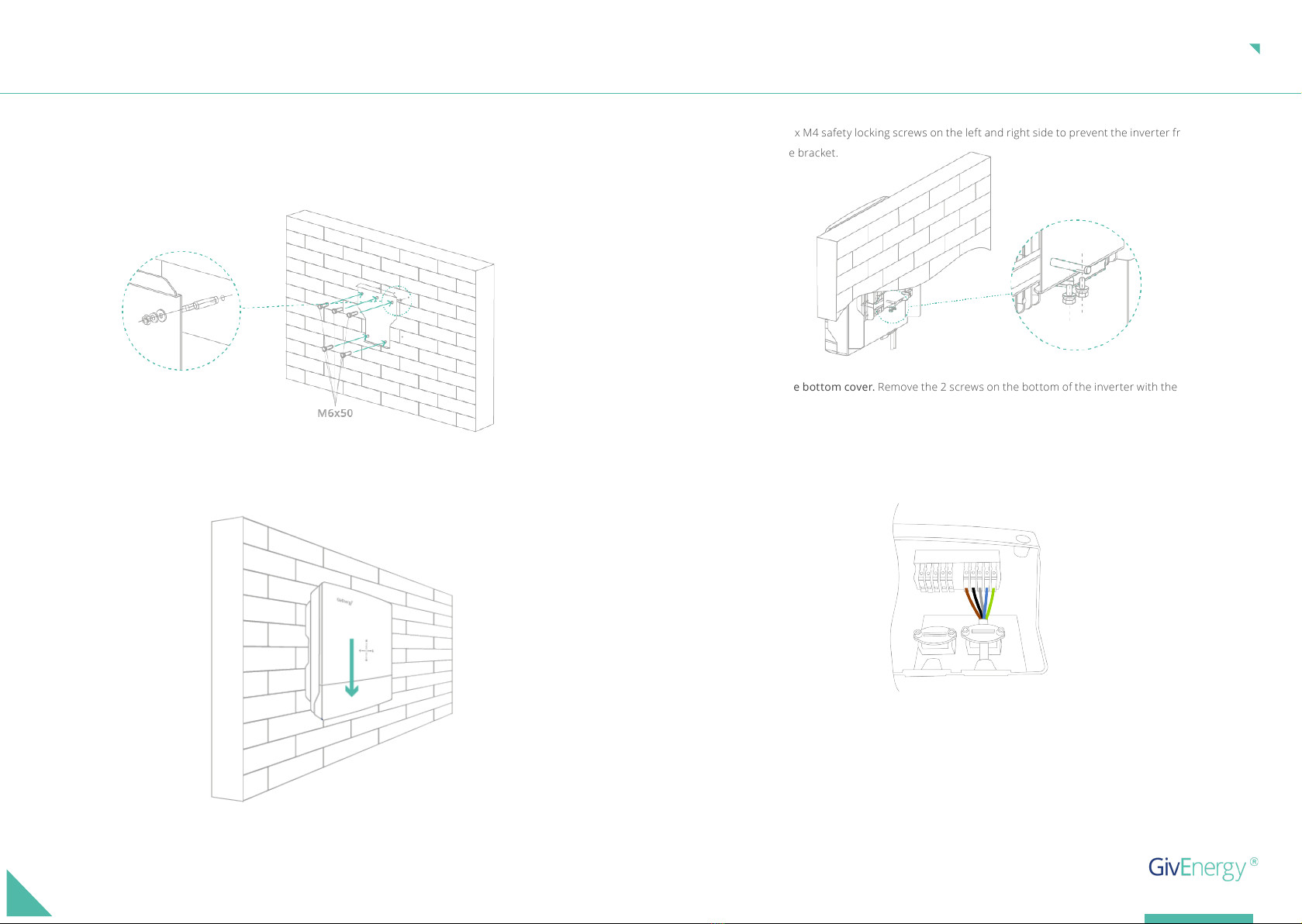
To connect the AC connector:
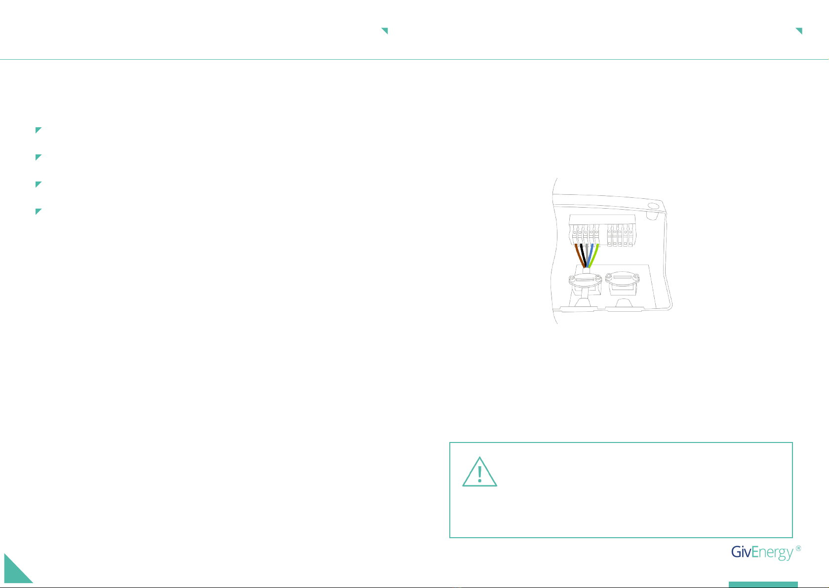
To connect the meter connections:
The PP cable will also need to have a grommet. If installing a battery, remove the PP cable from the
HV installation kit. To connect the PP cable to the inverter, make sure to use the right end of the cable.
The grommet end is the inverter end.
a. Connect the cables to their respective connection ports
a. Push and hold the orange tab
a. Pull down the red tab
c. Push the red tab back in
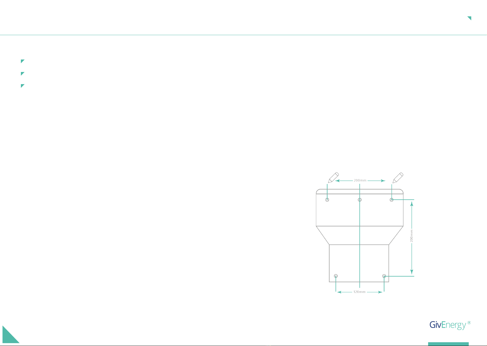
b. Cut a hole in the cable grommet
b. Plug in the cable
b. Push the connector into the socket until it clicks
d. Check that the grommet is positioned correctly
c. Release the orange tab
c. Put the saddles over the cables to ensure they stay where they are
d. Pull the cable slightly to ensure it is secure
d. For the LAN cable, make a cut down the middle of the grommet and place back in
its original position
9.
10.
11.
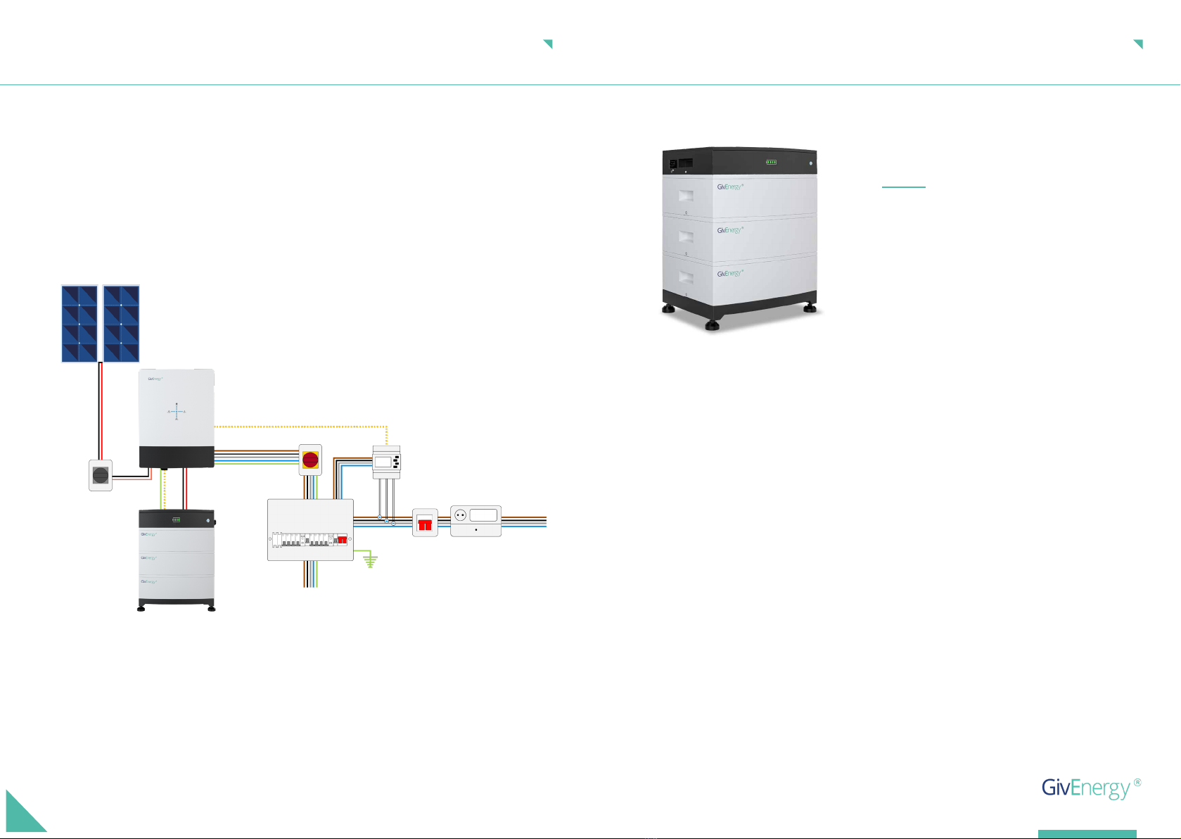
Test polarity of the PV cables.
4G Dongle. Adjust all dipswitches to o and place the dongle into the USB port under the inverter.
Use the securing screws to secure in place.
Replace the bottom front cover by sliding it up from the bottom of the inverter. Make sure that all of
the grommets are seated properly. Replace the 2 securing bolts under the inverter, taking care not to
overtighten.
Note: Everything is currently isolated and the inverter is not yet live.
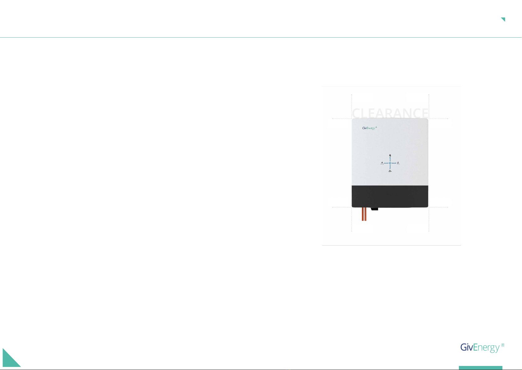
There must be adequate clearance around the inverter to allow for heat dissipation. The diagram
below illustrates the space required around the inverter.
When maintaining and cleaning the inverter, the whole system must be powered down. Clean with a soft
cloth with a light detergent if needed.
To ensure your inverter operates optimally at all times, annual maintenance checks need to be carried out.
Check for visible damage or discolouration of the switch, and that the cables are intact. Please ensure that
the top of the inverter is not obstructed in any way.
We recommend operating the rotary isolator from ON to OFF 5 times, this cleans the contacts of the rotary
switch.
Space Clearance
Maintenance
300mm 300mm
250mm
250mm
250mm
250mm
250mm250mm
CLEARANCE AND MAINTENANCE

Item Item Name
CONNECTIONS OVERVIEW
C
E
D
F
G
H
B
A
Battery connection pointA
PV Input x 2B
Built-in WiFi aerialC
EPS ConnectionE
DCommunication and LAN Connectors
FAC Connection
GDC Input Isolation Switch
H
I
J
Cable Clamps
Dipswitch
IP65 Cable Entry Glands
J
I
COMMUNICATION CONNECTIONS
WiFi
Communication/network ports
Dip Switches
USB LAN
Dipswitch
WAKE UP
METER
WATER
HEATER
DEBUG485
CAN
LAN DRM
ON OFF
+ +

Cable size requirements for the 3-Phase Hybrid Inverter are dependent on the model and the legislation of
the country it is being installed.:
The installer must calculate the size of cable needed based on the legislation and cable run length.
AC UTILITY GRID CONNECTION
3HY 6.0 - minimum 4mm² - 16mm²
3HY 10.0 - minimum 4mm² -16mm²
3HY 8.0 - minimum 4mm² -16mm²
3HY 11.0 - minimum 4mm² - 16mm²
CONNECTING TO THE EPS
The Emergency Power Supply (EPS) can provide a maximum output power of up to 11000W during a grid
failure. This output must be protected as close to the inverter as possible, with a double pole 30mA RCD
rated at up to 20A.
There are four approved methods to connect to the EPS, please refer to the EPS Connection Guide on our
Knowledge Base for more information.
If the backup terminals are used, please ensure the following:
The EPS MAX output power is 11000W. If the EPS goes over its max output, the
inverter will go into fault. The EPS output will only operate when the battery(s)
have capacity available.
Any other grid tied generation must be supplied from the grid side of the
changeover switch to avoid damage to the inverter, and void in warranty (see
the following diagrams for reference).
Backup
connection
terminals
An earth rod must be installed and connected to the main earthing terminal, as close to the origin of supply
as possible, and adequate overload / short circuit protection must be installed in accordance with the local
wiring regulations.

CONNECTING GRID METER TO INVERTER
In the system, a mid approved meter must be installed to ensure correct monitoring of the grid power. The
inverter uses this information to decide whether to charge or discharge the battery.
The CT clamps connected to the mid approved meter must be installed around the live incoming supply
to the property, with the arrow pointing in the direction of grid import, in order to monitor the complete
consumption of the building.
For further information, please refer to the meter guide on the Knowledge Base.
SPECIFICATIONS
Specications
Our stackable battery is designed to work alongside
the GivEnergy 3-Phase Hybrid Inverter.
High voltage BMS allows for greater charge and
discharge power running at a lower current,
providing higher eciency than our lesser voltage
range.
Customised power, to your property
S TACK A BLE BAT TERY
Max. Dimensions (20.4kWh)
1085H x 380D x 480W (mm)
Max. Current
Warranty
25 VDC
12 years
Max. Weight
226.3 Kg
Voltage
187 - 520 VDC
Standard Charge/Discharge
0.5C
Charging temperature
0ºC - 55º
Max. Capacity
20.4 kWh / 51 Ah
Max. Voltage
520VDC

BOX CONTENTS
GIV-BAT HV Kit
Battery (10.2kWh)
Battery (17.0kWh)
Battery (13.6kWh)
Battery (20.4kWh)
Item
Item
Item
Item
Item
Qty
Qty
Qty
Qty
Qty
Base Plate
Battery
One battery is 3.4kWh. A minimum of 3 batteries is required and a maximum of 6 is possible.
Battery
Battery
Battery
1
3
5
4
6
HV Box
Giv-Bat HV Kit
Giv-Bat HV Kit
Giv-Bat HV Kit
Giv-Bat HV Kit
Screws
Screws
Screws
Screws
1
1
1
1
1
2
2
2
2
Cable Inverter to HV Box 1
Template / Positioning Part
Wall Bolts
M6 Screws (securing battery stack)
Plug to Plug Cable with Grommet
1
2
2
1
Introduction
Installation Requirements
Installation of all GivEnergy equipment must be carried out by a GivEnergy approved installer.
HV Unit Information
The stackable batteries are designed to work with a GivEnergy 3-Phase Inverter.
Storing the Battery
The units must be stored in their original packaging at temperatures between -30ºC - 60ºC.
If any damaged or missing parts are found, please contact GivEnergy on 01377 252 874 or email
support@givenergy.co.uk immediately. Returns must be provided in original or equivalent packaging. The
cardboard packaging is recyclable.
When unpacking, please check the following:
Recycle as much as possible and dispose of waste in the correct place.
The units must be safely removed by a qualied professional. Local regulations must be adhered to and
disposed of at the correct recycling place.
Disposing of Hardware at the end of its lifetime
Packaging Contents
Disposing of Packaging
All information contained in this booklet refers to the assembly, installation, commissioning, and
maintenance of the stackable batteries. Please retain this manual for future reference.
GENERAL INFORMATION
Legal Disclaimer: This document is the property of GivEnergy, reproduction is prohibited.
There are no missing accessories from the packaging list
The model and specication of the battery’s nameplate match the order specications

Item Item Name
STATUSA
ON/OFF SwitchB
HV BoxC
D
E
H
F
I
G
J
Rotary Isolator
Battery packs
Securing screws
Base plate
Earthing point
Adjustable feet
Battery connection point
SYSTEM APPEARANCE
B
A
F
E
D
C
I
J
H
G
Only GivEnergy supplied battery cables must be used
Do not use the battery if there are any deformities, such as bulging or leakages
Do not puncture the battery
Do not throw the battery or use forceful impact
Do not attempt to repair the battery yourself (please call your Approved Installer)
The battery must be installed vertically, never install horizontally, avoid tilting the unit
Do not install in direct sunlight
Installation Instructions and Precautions
Extra care and attention must be taken when installing and maintaining any GivEnergy equipment.
The system is capable of lethal voltages, even when disconnected
Safety Instructions
If any damaged or missing parts are found, please contact GivEnergy on 01377 252 874 or email
support@givenergy.co.uk immediately. Returns must be provided in original or equivalent
packaging. The cardboard packaging is recyclable.
If you suspect something is wrong with the battery, contact GivEnergy on 01377 252 874 or email
support@givenergy.co.uk.
SAFETY AND INSTALLATION
All electrical installations must be carried out by a qualied and registered electrician and in
accordance with the IEE Wiring Regulations
All GivEnergy equipment must be installed by a GivEnergy approved installer
Ensure batteries are always xed to the wall using the mounting bracket, even when the weight of the
product is on the oor
Externally mounted batteries must always be wall mounted above the frost-line or a minimum of 50mm
An earth bond must be installed between all batteries and inverters
Do not remove the front cover unless instructed by the GivEnergy support team

1.
Stack the battery modules on the base making sure they are ush to the wall. Adjust the feet to make
sure they are ush to the wall and level left and right. Once all of the battery packs are in place use
the template to determine the location of the wall bolts. Ensure the template is level and completely
ush to the wall.
2.
STEP-BY-STEP INSTALLATION
Place the base plate down as close to the wall as possible. The base plate needs to be ush to
the wall. Cut out the skirting board if in the way.
Drill two holes at the marked points to suit the xings. Install and tighten the two expanding bolts,
leaving a 3mm gap between the bolt head and the wall to secure the HV Box.
Place the HV box on top of the batteries.
Make sure the isolator is switched o before putting on the HV box.
Use the template/positioning part to mark holes for the 2 bolts for the HV box.
4.
6.
5.
3.
Connect all of the packs together (including base plate and HV Box) using the supplied screws on both
sides.
7.
STEP-BY-STEP INSTALLATION

CONNECTING THE BATTERY TO THE INVERTER
Connect the cable to the battery and the other end to the inverter. Ensure that the grommeted
end of the cable is the inverter end. Push the plug until there is a click, lock in place using the red
tab.
Make sure there is one cable (under local legislation, 6mm2 earth cable suggested) running from
one of the earthing points on the bottom of the inverter to the earthing point on the stackable
battery.
1.
2.
When ready to power up the unit, switch on the rotary isolator on the battery. Push and hold
the button for 2 seconds to switch on the battery stack. The lights should then illuminate.
The system is now ready for commissioning.
3.
Plug to plug battery cable
One type of cables exist for connection to the stackable battery:
IMPORTANT
Battery
end
Inverter
end
All stackable battery cables are included with the product.
Note: make sure the plug is fully plugged in.
Beware of inverter end and battery end.
Instructions on how to install the cable are also on the plug itself.
BATTERY CABLES
To disconnect the cable:
To connect the cable:
Pull down the red tab
Push in the connector
Push the red tab down
Pull in the red tab
Press the orange tab
1.
1.
2.
2.
3.

START-UP AND SHUT-DOWN OF THE SYSTEM
Start-Up Procedure
Shutdown Procedure
Connect the AC circuit breaker, ensure that the system is powered.
1.
Turn o the battery by pressing the button on the front until lights have gone out1.
Disconnect the AC circuit breaker to prevent it from being reactivated4.
Check to see that the status light in the centre is ashing2.
Switch o the battery isolator to prevent it from being reactivated2.
The PV indicator should light up on the inverter (if the sun is shining)
Turn on the battery isolator
Push the button on the front of the battery until the LED lights up
Wait for the relays to start up
Make sure that the battery has a green status
The battery indicator on the inverter should light up
The system is ready to be commissioned as soon as it is powered up. Commission using the portal/
app. Ensure that the grid power is reading identical to that of the mid approved meter (this can be
found on the screen of the meter).
4.
5.
6.
7.
8.
9.
10.
Turn o the PV switch3.
Wait until all LEDs have gone out. The inverter is now shut down
5.
3. Turn on the PV switch
COMMISSIONING A SYSTEM
All systems must be commissioned to ensure correct battery and meter communications, as well as
connection to the online portal.
Note: If commissioning is incomplete, leave the battery o to avoid it going at. Without
commissioning, the system may not operate correctly.
Check that all the wires are securely connected before the battery isolator and the AC isolator is
switched on. You MUST set the parameters of the battery according to your battery system.
The inverter is connected to the internet and the connection guide has been followed correctly.
Please ensure the following conditions are met before commissioning:
Sign into the online portal at https://portal.givenergy.cloud with your GivEnergy Engineer login.
If you are a rst time user, and you do not have an account or Engineer login, please consult your
supplier to get this set up.
Accessing the Commissioning Portal
To download a fully illustrated guide, please visit our Knowledge Base at www.givenergy.co.uk

There must be adequate clearance around the batteries to allow for heat dissipation. The diagram
below illustrates the space required around the inverter.
When maintaining and cleaning the stackable battery, the whole system must be powered down. Clean
with a soft cloth with a light detergent if needed.
To ensure your stackable battery operates optimally at all times, annual maintenance checks need to be
carried out. Check for visible damage or discolouration of the switch, and that the cables are intact. Please
ensure that the top of the stackable battery is not obstructed in any way.
We recommend operating the rotary isolator from ON to OFF 5 times, this cleans the contacts of the rotary
switch.
Space Clearance
Maintenance
300mm 300mm
300mm300mm
300mm300mm
CLEARANCE AND MAINTENANCE DIP SWITCHES AND STATUS INDICATORS
What does the STATUS light mean?
Shut downOFF
Battery Energy. Flicker - Battery chargeGreen
System bootGreen light
Red
Sound
System failure
Firmware update or a fault (please consult the app or portal)
Status indicators

PARAMETER AND MODEL COMPARISON TABLE
GIV-BAT
10.8-HV
Parameter type
Height above ground (L)
High Voltage (UH)
Low Voltage (UL)
Measuring Voltage (UM1)
Measuring Voltage (UM2)
575mm
262.8Vd.c
201.6Vd.c
237~243Vd.c
216Vd.c
GIV-BAT
13.6-HV
GIV-BAT
17.0 - HV
GIV-BAT
20.4-HV
725mm
350.4Vd.c
268.8Vd.c
316~324Vd.c
288Vd.c
875mm
438.0Vd.c
336.0Vd.c
395~405Vd.c
360Vd.c
1025mm
525.6Vd.c
403.2Vd.c
474~486Vd.c
432Vd.c
DECOMMISSIONING A SYSTEM
Uninstalling the Inverter
Uninstalling a Battery
If possible, always pack the inverter in its original packaging and secure it with tension belts. If this is not
available, you may also use an equivalent sized box. The box must be capable of being closed completely
and be strong enough to support both the weight and the size of the inverter.
Packaging the Inverter
Store the inverter in a dry place where ambient temperatures are always between -25ºC and +60ºC
Storing the Inverter
Follow the shut-down procedure
1.
1.
Remove all connections and cables from the inverter
Remove all cables
2.
2.
Remove the bolts which are securing the inverter to the bracket
Remove the bolts securing the HV box
3.
3.
Lift the inverter o the bracket
Lift the HV box
Lift o all of the battery packs
Remove the base plate
4.
4.
5.
6.
Remove the wall bracket5.

WORK MODES & TROUBLESHOOTING
The system optimises the delivery of generated PV power and battery power to prioritise the
home load. Grid power is used as a last resort if solar and battery power are unavailable.
Eco Mode
This is prioritised to charge the battery during o peak times when energy is cheaper, greener,
and cleaner. The battery will start to discharge outside of the o peak time when energy is
more expensive.
O Peak Charging
The system has the ability to be used in the event of a power cut. To utilise this feature, circuits
must be connected to the inverter’s EPS terminals.
To download a fully illustrated guide on connecting the inverter to the EPS, please visit our
Knowledge Base at www.givenergy.co.uk.
Back Up / Island Mode
If you have any questions, please contact GivEnergy on 01377 252 874 or email
support@givenergy.co.uk. Alternatively, visit our troubleshooting guide on the knowledge base at
www.givenergy.co.uk.
MANUFACTURER WARRANTIES
This inverter and stackable battery are covered by a 12-year warranty. Please refer to the warranty
document for further specications.
Products Covered
12 years
12 years
12 years
12 years
Hybrid Inverter Gen 3
3-Phase 6.0
Hybrid Inverter Gen 3
3-Phase 10.0
Hybrid Inverter Gen 3
3-Phase 8.0
Hybrid Inverter Gen 3
3-Phase 11.0
12 years
Stackable Battery | HV 10.2/ 13.6/ 17.0/ 20.4

SCAN ME
TO ACCESS ALL
AVAILABLE RESOURCES
This manual suits for next models
7
Other GivEnergy Batteries Pack manuals