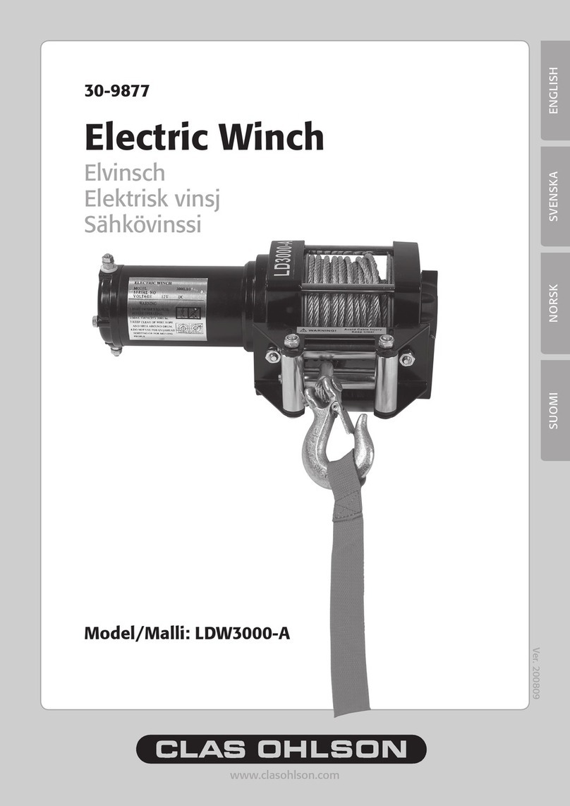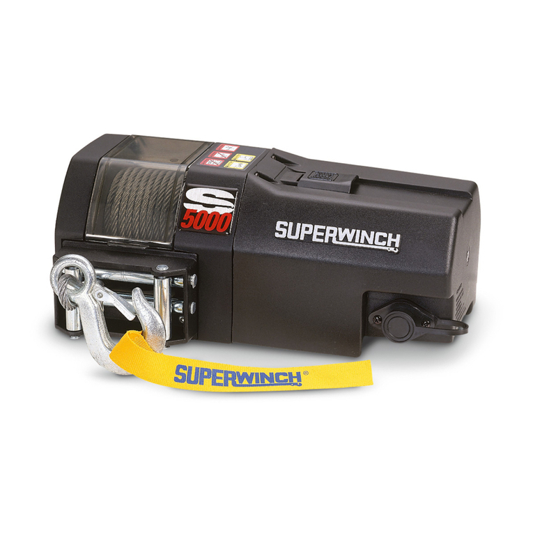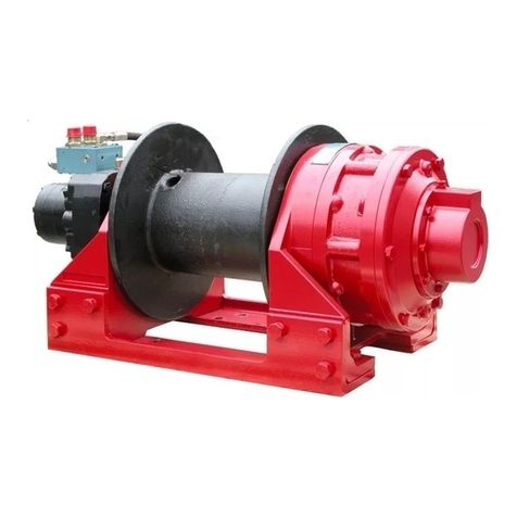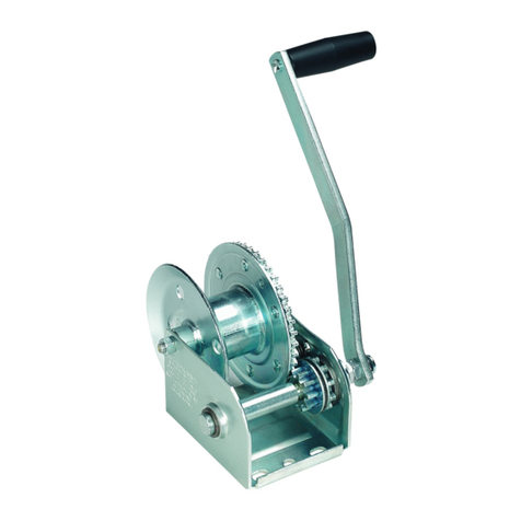
GENERALSPECIFICATIONDATA
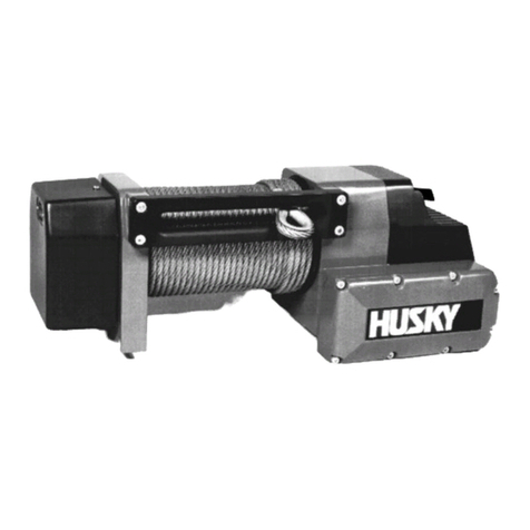
WINCH SPECIFICATION
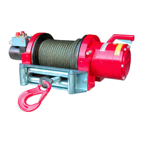
Type .......................................................... H9W
GearReduction ........................................ SteelcentredPhosphorBronzewormwheeldriven bycasehardened, groundandpolishednickel
steelwormrunninginsubstantialrollerballbearing,mountedinaheat treated aluminium housing.
Oillubricated forguaranteed long life.
Gearbox Ratio .......................................... 54:1
Drum ........................................................ Fabricatedsteelrunningincopolymermaintenance freebearingswith springloadedbrakes to
prevent over-run when pullingout therope.
Braking...................................................... The action oftheworm and wormgear providesfor substantial brakingaction
Freespool.................................................. Multi-splinedfor low contactpressure. Operatedby an easy action lever which disengages thegear
box to allow the wire rope to bepulledoutwithout usingelectricpower.
Mounting .................................................. Ficingpositions allowfor platformorin-chassis mounting in either underoroverwinding modes.
Model Designation.................................... H9W H9W
PartNo. .................................................... 8569 8588 &8589
Rated Line Pull BottomLayer .................. 40kN(9000 lbs) 40 kN(9000lbs)
Line Speed 1st. Layer (NoLoad) ............ 7.3 M/min (24 ft/min) 7.3M/min (24ft/min)
Max.Oil Pressure .................................... 124 bar (1800 p.s.i.) 124bar(1800p.s.i.)
Max.Oil Flow............................................ 45l/min (12US Gal.min) 45 l/min(12 US Gal.min)
RopeDiameter(Recommended).............. 10mm 10 mm
RopeLength ............................................ 14m(45 ft) 28 m (90ft)
Drum Diameter ........................................ 76.2mm (3”) 76.2 mm(3”)
Weight ...................................................... 28.5kg (63 lbs) 28.5 kg (63lbs)
HYDRAULIC SYSTEMSPECIFICATION
System Type ................................ Open system with filteredreturn line.
ReliefValve .................................. Set atwinch operating pressure.
Pump............................................ Withamax.oilsupplyof 60l/min(16U.S. gal/min) attopmotor rpm.Thepumpmustbecapable
ofdelivering a pressure of 130bar(1890lb/ in
2).
Reservoir...................................... Mustbefittedwithanoil filler devicecomprisingstrainer andair filter and adipstick. Thecapacityof
thetankshouldbeat least60litres(16U.S.gal).Note.Don’t fill thetankto thetop,since theremust
bespaceforexpansioninthetank.Suitable hydraulicoil isCastrolCRMLor equivalent(150LHM
32-68). Typicalviscosityrating of150-175cSTat 100°C (695-816SUSat212°F).
Hoses .......................................... Shouldhave theminimumfollowingdimensions:
Pressureand flow loss is increased as Pumpinlet line:1/2”NominalBore (N.B.).
hose length increases and/or bore size (reservoir to pump)
decreases. Pressure andreturn lines Return line:3/4” N.B.
nexcess of3.5 metres shouldbe (controlvalveto reservoir)
compensated withan increase in Pressure hoses :1/2”N.B.(Pipe;18x2mm -3/4” SCHED 80)
inominalbore size. (controlvalveto load control valve)
Pilotline, pipe :0 8-10 x 1mm -3/4”SCHED80
Motor caseDrain Line(Optional)1/4” Min. bore.
Controlvalve................................ 4-way,3-positionwithspring centred,closedcentre and builtinrelief valve. The reliefvalvemustbe
setatthewinch operating pressure. Thevalveshould be mountedasclosetothe winch as possible.
Hydraulic motor............................ Todrain line in necessary.SAE ported andfitted withBSP adaptors.
Oil Suction Strainerrating............ Approx.250 microns (0.010”).
Return Line Filter rating .............. 10-40 microns (0.0004”-0.0016”).
0
02-1
GENERAL SPECIFICATION DATA
