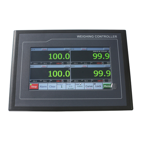
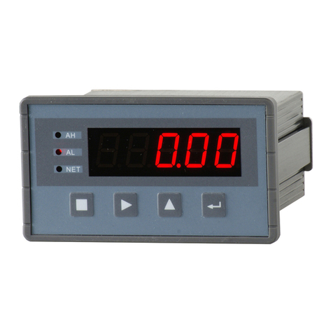
Supmeter BST100-E11 User manual

BB
STST
1010
0-0-
E1E1
1/1/
E0E0
1/1/
E2E2
1 W1 W
eigeig
hihi
nn
g Cog Co
ntnt
rr
olol
ll
erer
For: Ration Belt WeighfeederFor: Ration Belt Weighfeeder
OperatioOperatio
n n
MaMa
nunu
al V3al V3
.6.6
Changsha Supmeter TChangsha Supmeter T
echnolechnol
ogiogi
cal Co.,cal Co.,
Ltd.Ltd.

PrefacePreface
Thank you very much for your purchase!Thank you very much for your purchase!
This manual covers safety precaution, technical specification, operation interface, installation&This manual covers safety precaution, technical specification, operation interface, installation&
connection, function&operation and so on. In order to make the product running at its best, please read thisconnection, function&operation and so on. In order to make the product running at its best, please read this
manual in advance, and reserve it for the future reading.manual in advance, and reserve it for the future reading.
The continuous technology update, function improvement and quality enhancement may lead to someThe continuous technology update, function improvement and quality enhancement may lead to some
differences between this manual and the physical differences between this manual and the physical
product, please understand.product, please understand.
Without our authorization, the contents of this Without our authorization, the contents of this
manual are not allowed to manual are not allowed to
be copied and reproduced.be copied and reproduced.
Main Features:Main Features:
Suitable for Ration Suitable for Ration
Belt WBelt W
eighfeeder with Ration eighfeeder with Ration
Flow Feeding & Flow Feeding &
Ration WRation W
eight Batch eight Batch
Control.Control.
EMC design with high anti-jamming capabilitEMC design with high anti-jamming capabilit
yy
, suitable for , suitable for
industrial environment.industrial environment.
128×64 LCD display screen with 7 background colors for 128×64 LCD display screen with 7 background colors for
English/Chinese displayEnglish/Chinese display
..
Optional English keypad, Simplified Chinese keypad and COptional English keypad, Simplified Chinese keypad and C
omplexomplex
Chinese keypad.Chinese keypad.
Menu&Shortcut mode operation with key tone.Menu&Shortcut mode operation with key tone.
High-precisionHigh-precision
∑∑
--
△△
A/D conversion technology and broad-range speed pulse input A/D conversion technology and broad-range speed pulse input
circuit.circuit.
Max. ConneMax. Conne
ction Quantity: 8 Loadcells (350Ω).ction Quantity: 8 Loadcells (350Ω).
Auto-locking, Key-locking, Key-unlocking, Digital Setting&Calibration and I/O TestingAuto-locking, Key-locking, Key-unlocking, Digital Setting&Calibration and I/O Testing
functions available.functions available.
Auto Zero TrackingAuto Zero Tracking
, Speed Calibration and Belt , Speed Calibration and Belt
Length Calibration functions available.Length Calibration functions available.
One optional ‘Flow Setpoint’ analog signal input [AI: 4~20mA].One optional ‘Flow Setpoint’ analog signal input [AI: 4~20mA].
Max.3 definable ‘Flow/Control Current /…’ analog signal outputs [AO: 4~20mA].Max.3 definable ‘Flow/Control Current /…’ analog signal outputs [AO: 4~20mA].
Quick and steady PID for ration feeding control available.Quick and steady PID for ration feeding control available.
3 Definable normally open switch inputs [DI] and 4 definable normally open relay switch3 Definable normally open switch inputs [DI] and 4 definable normally open relay switch
outputs [DO].outputs [DO].
The feeder and belt weigher can be started and stopped by DI&DO signal.The feeder and belt weigher can be started and stopped by DI&DO signal.
1 ‘Totalized Weight High-speed Pulse’ output [PO].1 ‘Totalized Weight High-speed Pulse’ output [PO].
2 Optional communication ports for linking to IPC/PLC, LED Remote Display, Serial Printer2 Optional communication ports for linking to IPC/PLC, LED Remote Display, Serial Printer
and Wireless Module.and Wireless Module.
WW
eight Records per shift/day/month of a eight Records per shift/day/month of a
year can be queried and year can be queried and
printed.printed.
With the multitasking mode, the weighing&control process will not be interrupted by parameterWith the multitasking mode, the weighing&control process will not be interrupted by parameter
setting and the other operations.setting and the other operations.
Model HorizonModel Horizon
tal Patal Pa
nel-mountnel-mount
inging
: E1: E1
11
Model Model
VV
ertical ertical
PaPa
nel-mounnel-moun
ting: ting:
E0E0
11
Model Model
WW
all-mountall-mount
ing: ing:
E2E2
11

ContentsContents
1. SAFETY PRECAUTION 1. SAFETY PRECAUTION
..............................................................................................................................................
..........................................4..........................................4
2. 2.
TECHNICAL SPECIFICTECHNICAL SPECIFIC
AA
TION .......................................................................TION .......................................................................
.............................5.............................5
3. 3.
OPERAOPERA
TION INTERFTION INTERF
ACE .........................ACE .........................
..................................................................................................................................................................
..7..7
3.13.1
MM
ODELODEL
HH
ORIZONTALORIZONTAL
PP
ANELANEL
--
MOUNTINGMOUNTING
OO
PERATIONPERATION
II
NTERFNTERF
ACEACE
......................................................... 7......................................................... 7
3.23.2
MM
ODELODEL
VV
ERTICALERTICAL
PP
ANELANEL
--
MOUNTINGMOUNTING
OO
PERATIONPERATION
II
NTERFANTERFA
CECE
.............................................................. 8.............................................................. 8
3.33.3
MM
ODELODEL
WW
ALLALL
--
MOUNTINGMOUNTING
OO
PERATIONPERATION
II
NTERFANTERFA
CECE
................................................................................ 9................................................................................ 9
3.43.4
KK
EYPADEYPAD
OO
PERATIONPERATION
............................................................................................................................ 10............................................................................................................................ 10
3.53.5
SS
TATETATE
II
NDICANDICA
TIONTION
............................................................................................................................... ...............................................................................................................................
1111
4. 4.
INSTINST
ALLAALLA
TION&CONNETION&CONNE
CTION ..............................................................................................CTION ..............................................................................................
1212
4.14.1
II
NSTNST
ALLAALLA
TIONTION
..................................................................................................................................... 12..................................................................................................................................... 12
4.1.1 Model 4.1.1 Model
Panel-mounting Installation ........................................................................................... 12Panel-mounting Installation ........................................................................................... 12
4.1.2 4.1.2
Model Wall-mounting Installation ............................................................................................. 13Model Wall-mounting Installation ............................................................................................. 13
4.24.2
TT
ERMINALERMINAL
........................................................................................................................................... 14........................................................................................................................................... 14
4.2.1 4.2.1
Model Horizontal Model Horizontal
Panel-mounting Terminal Panel-mounting Terminal
............................................................................. 14............................................................................. 14
4.2.2 4.2.2
Model Wall-mModel Wall-m
ounting Terminal ................................................................................................ 14ounting Terminal ................................................................................................ 14
4.2.3 4.2.3
Model Model
VV
ertical ertical
Panel-mounting Terminal Panel-mounting Terminal
.................................................................................. 15.................................................................................. 15
5. OPERATI5. OPERATI
ON PROCEDURE ........................................................................................................ON PROCEDURE ........................................................................................................
2020
6. 6.
FUNCTION&OPFUNCTION&OP
ERAERA
TION ..........................................................................................................TION ..........................................................................................................
2121
6.16.1
MM
AINAIN
DD
ISPLAYISPLAY
II
NTERFNTERF
ACEACE
.................................................................................................................. 21.................................................................................................................. 21
6.1.1 Totalized W6.1.1 Totalized W
eight, Flow eight, Flow
& Belt & Belt
Speed ....................................................................................... 21Speed ....................................................................................... 21
6.1.2 Totalized W6.1.2 Totalized W
eight, Flow eight, Flow
& Flow & Flow
Setpoint .................................................................................. 21Setpoint .................................................................................. 21
6.1.3 Totalized W6.1.3 Totalized W
eight, Flow eight, Flow
& Control & Control
Current ............................................................................... 22Current ............................................................................... 22
6.1.4 Totalized W6.1.4 Totalized W
eight, Load eight, Load
& Load & Load
Setpoint .................................................................................. 22Setpoint .................................................................................. 22
6.1.5 Totalized W6.1.5 Totalized W
eight, Date eight, Date
& Time ................................................................................................. 23& Time ................................................................................................. 23
6.1.6 Totalized W6.1.6 Totalized W
eight, Batch eight, Batch
WW
eight & eight &
Batch Weight Setpoint........................................................ 23Batch Weight Setpoint........................................................ 23
6.1.7 Alarm Ite6.1.7 Alarm Ite
ms ............................................................................................................................... 24ms ............................................................................................................................... 24
6.1.8 6.1.8
DI&DO DI&DO
...................................................................................................................................... 25...................................................................................................................................... 25
6.1.9 AI&AO ...................................................................................................................................... 256.1.9 AI&AO ...................................................................................................................................... 25
6.1.10 AD V6.1.10 AD V
alue, Totalized Weight Pulse, alue, Totalized Weight Pulse,
Total WTotal W
eight eight
of of
Present Shift ........................................... 25Present Shift ........................................... 25
6.26.2
MM
AINAIN
MENU ...................................................................................................................................... 26MENU ...................................................................................................................................... 26
6.3.1 Basic
Scale Par
ameters
.............................................................................................................. 28
6.3.2 Extra
Scale Parameters .............................................................................................................. 29
6.3.3 Basic
Control Parameters .......................................................................................................... 30
6.3.4 Extra Control P
arameters .......................................................................................................... 31
6.3.5
Flow Parameters ........................................................................................................................ 32
6.3.6 Speed Parameters ......................................................
................................................................ 33
6.3.7
Load Parameters ........................................................................................................................ 34
6.3.8 Weigh
t Record
Parameters ........................................................................................................ 34
6.3.9
Communication Parameters
....................................................................................................... 35
6.3.10 I
/O Parameters ......................................................................................................................... 36
6.3.11 Display
Parameters .................................................................................................................. 38
6.3.12 Date/Time Parameters .............................................
................................................................ 38
6.3.13 A Sample of
Parameter
Setting
................................................................................................ 39
6.4
F2
S
YSTEM
C
ALIBRATION
................................................................................................................... 40
6.4.1 Zero Calibration ........................................................
................................................................ 40
6.4.2 Dynamic Span Calibration
........................................................................................................ 41
6.4.3 Static Span
Calibration with
Chain W
eight ............................................................................... 42
6.4.4 Static
Span Calibration
with Hanging Weight
........................................................................... 44
6.4.5 Segmenting
Span Correction .....................................................................................................
46
6.4.6 Speed
Calibration ......................................................................................................................
48
6.4.7 Belt
Length Calibration .............................................................................................................
49
6.5
F3
W
EIGHT
R
ECORD FOR
Q
UERYING
&P
RINTING
................................................................................ 50
6.6
F4
D
ATA
C
LEARING
.............................................................................................................................
51
6.7
F5
S
ECURITY
.......................................................................................................................................
52
6.7.1 Auto-locking .............................................................................................................................. 52
6.7.2
Key-locking
............................................................................................................................... 53
6.7.3
Key-unlocking
........................................................................................................................... 53
6.7.4 Password Set..............................................................
................................................................ 54
6.7.5
RAM Reset ................................................................................................................................ 55
7.
RA
TION
FLOW AUTO-FEE
DING SYSTEM .............................................................................56
APPENDIX A. PRINT FORMATS ...................................................................................................57
APPENDIX B.
COMMUNICA
TION
PROTOCO
LS
......................................................................
58

1. Safety Precaution
Lithiu
m Battery Installa
tion
A
Lithium
battery
should
be
equipped
in
the
product.
If
it
is
not
allowed
to
be
transported
together with the product because of embargo, please make a purchase according to the
model offered by us and install it by yourself.
Prohibit using th
e p
roduct
under da
ngerous
environment
Prohibit using the product under the dangerous
environment
with combustible gas and
explosive dust. If you have
this need, please use our
explosion-pr
oof products.
Av
oi
d u
si
ng
t
he p
r
od
uc
t
un
der
ov
erh
eated
environment
Make sure that the product works under the
environment
with allowed temperature range to
get good performance and long working life.
Please keep the product away from direct sunlight. If it is installed in a cabinet, please install
cooling fans on the top of the cabinet.
Controller Grounding Protection
The product, as a low-voltage equipment, should be kept away from the high-voltage
equipments.
For avoiding bodily injury from electric shock accident and k
eeping the product separate from
strong interfere
nce, the metal shell of
the product should be grounded directly and
the ground
resistance should be less than 4Ω.
Scale Frame Grounding Protection
For avoiding bodily injury from electric shock accident and keeping the loadcells and speed
sensor separate from strong interference, the scale frame should be connected with the
electronic scale grounding net and the
ground resistance should be less than 4Ω.
Ca
ble Laying
Weighing signal, speed signal, analog signal and communication signal cables should be laid
in pipes, and do not lay them
together wi
th power cables.
Power Supply
Please make sure that the inputted voltage is correct before power-on.
If the voltage fluctuation exceeds the allowed range, please use a power stabilizer to get a
stable voltage supply.
Environmenta
l
P
rotection
Before the Lithium battery equipped in the product being discarded, please insulate its
positive or negative pole, do not put it into fire.
Although
the
product
is
made
of
the
lead-free
components,
after
used
in
the
industria
l
environments, it’s possible to be polluted. So, while being discarded as worthless, the product
should be processed lawfully as leady industrial waste for environment protection.
Other Notes
The installation, wiring and maintenance should be operated by the engineers with the
relevant professional knowledge and safety operation ability. Although being not described in
this manual, the relevant safety operating procedures and standards should be followed.

2. Technical Specification
Executing Standard
CMC GB/T 7724-2008
《
Electronic Weigh
ing
Meter
》
PRC National Standard.
OMIL R50:1997
《
Continuous Totalizing Automatic W
eighing I
nstruments
》
International
Recommendation.
Accuracy Grade: 0.5.
Display
128×64 LCD display screen with 7 background colors
for English/Chinese display.
Display Refreshing Time: Setting Range 0.1~2.0s.
Kaypad
Optional 16-key English keypad, Simplified Chinese keypad and
C
omplex
Chinese keypad.
Menu&Shortcut operation with key tone.
Loadcell Interface
Excitation Voltage/Max. Current: DC10V/250mA [8-
350Ω
loadcells].
Signal Input Range: 0~25mV.
∑
-
△
ADC: 24-bit, 100,000 internal code used.
Sampling Frequency: 200Hz.
Zero Drift: ±0.1
μ
V/
℃
R
TI (Relative
to Input).
Gain Drift: ±5ppm/
℃
.
Non-linearity: 0.005%FS.
Speed Sensor Interface
Output Voltage/Max. Current: DC12V/100mA.
Speed Pulse Input Range: 0.5~3000Hz.
Switch Signal Interface
3 Normally Open Switch Inputs [DI].
4 Normally Open Relay Switch Outputs [DO]: AC250V/DC24V, 1A.
1 ‘Totalized Weight High-speed Pulse’ Output [PO]: 100mA, DC5~24V; Weight per Pulse and
Pulse Width can be preset.
Analog Signal Interface
Max.3 Definable ‘Flow/Control Current /
…’ An
alog Signal Outputs
[AO]: 4~20mA, Non-linearity:
0.05%FS; AO
3 is
optional.
1 Optional ‘Flow Setpoi
nt’
Analog Signal Input [AI]:
4~20mA, Non-linearity: 0.05%FS.
Digital Communication Interface
COM1: Optional
RS232/RS485/RS
422/Profibus-DP/Ethernet modules.
COM2: RS232.

4.1.2
Model Wall-
mounting Installation
Outline Size
W×H×D[mm]
Mounting Size
W×H[mm]
Mounting Hole Size
[mm]
202×305×90 169×271
Ф9
Outline Size
Installation Mode

4.2 Terminal
4.2.1
Model Horizontal
Panel-mounting T
erminal
4.2.2 Model Wall-mounting Terminal
AO/A
I/PO
A
O
1
+
A
O
1
-
A
O
2
+
A
O
2
-
A
O
3
+
A
O
3
-
A
I
+
A
I
-
V
I
N
P
O
DO/DI
D
O
1
+
D
O
1
-
D
O
2
+
D
O
2
-
D
O
3
+
D
O
3
-
D
O
4
+
D
O
4
-
C
O
M
D
I
1
D
I
2
D
I
3
POWER
L
E
N
B
-
(
T
X
D
-
)
A
+
(
T
X
D
+
)
D
P
-
(
R
X
D
+
)
(
R
X
D
-
)
D
P
+
G
N
D
R
X
D
T
X
D
+
5
V
COM1 COM2
Optional
Modules
Fixed
on
PCB
1
9
LOADCELL
SENSOR
S
I
G
-
S
I
G
+
E
X
C
-
E
X
C
+
S
H
D
V
S
-
S
I
N
V
S
+
S
E
N
+
S
E
N
-
SPEED
1 10
SENSOR
V
S
+
S
I
N
V
S
-
S
H
D
E
X
C
+
E
X
C
-
S
I
G
+
S
I
G
-
S
E
N
-
S
E
N
+
AO/A
I/PO
P
O
V
I
N
A
I
-
A
I
+
A
O
3
-
A
O
3
+
A
O
2
-
A
O
2
+
A
O
1
-
A
O
1
+
DO/DI
D
I
3
D
I
2
D
I
1
C
O
M
D
O
4
-
D
O
4
+
D
O
3
-
D
O
3
+
D
O
2
-
D
O
2
+
D
O
1
-
D
O
1
+
COM1/2
POWER
N
L
E
ETHERNET

4.2.3 Model Vertical Panel-mounting Terminal
PO
VIN
AI-
AI+
AO3-
AO3+
AO2-
AO2+
AO1-
AO1+
A
O
/
A
I
/
P
O
DI3
DI2
DI1
COM
DO4-
DO4+
DO3-
DO3+
DO2-
DO2+
DO1-
DO1+
D
O
/
D
I
C
O
M
1
/
2
N
L
E
P
O
W
E
R
E
T
H
E
R
N
E
T
S
E
N
S
O
R
VS+
SIN
VS-
SHD
EXC+
EXC-
SIG+
SIG-
SEN-
SEN+

No.
Pin
Description
SENSOR
Loadcell
/
Speed
Sensor
Port
LOADCELL Loadcell
Connectio
n
Mode
6-Wire
4-Wire
[Default Set]
1
SEN+
Feedback
V
oltage
+.
2
SEN-
Feedback
V
oltage
-.
3
SIG-
W
eighing
Signal
[mV]Inp
ut
-.
W
eighing
Signal
[mV]Inp
ut
-.
4
SIG+
W
eighing
Signal
[mV]Inp
ut
+.
W
eighing
Signal
[mV]Inp
ut
+.
5
EXC-
Excitatio
n
V
oltage
-.
Excitatio
n
V
oltage
-.
6
EXC+
Excitatio
n
V
oltage
+
[DC10V]
.
Excitatio
n
V
oltage
+
[DC10V]
.
7
SHD
Shield
Ground.
Shield
Ground.
SPEED
Speed Sensor
3-Wire
[NPN Open-collector Output Type]
2-Wire
Tachogenerator
8
VS-
V
oltage
Output
-.
Pulse
Signal
Input
-.
9
SIN
Pulse
Signal
Input.
Pulse
Signal
Input
+.
Sine Wave Signal Input
Terminal 1.
10
VS+
V
oltage
Output
+
[DC12V]
.
Sine Wave Signal Input
Terminal 2.
POWER
AC220V[±15%]
Power
Input
Port
1
N
Null
Wire.
2
E
Protective
Ground.
3
L
Live
Wire.
The metal shell should be
grounded directly to avoid electric shock.

6.3.7 Load Parameters
No.
Parameter
Range
Default
Set
P500
Decimal
(LoadDecimal Point)
0: o
1: o.o
2: o.oo
1
P501
Load
Range
0.01~5000.00kg/m
([P107] Scale Unit = kg)
100.00
0.01~5000.00g/m
([P107] Scale Unit = g)
P502
Load Upper
(Load Upper Limit)
(0.0~100.0
)%
Load
Range
100.0%
P503
Load Lower
(Load Lower Limit)
(0.0~100.0
)%
Load
Range
0.0%
P504
Load
Filter
1~20
10
P505
Calc.
Speed
0.000 (Use external speed for
Load calculation)
0.001~5.000
m/s (Used for
Load calculation)
0.000
6.3.8 Weight Record Parameters
No.
Parameter
Range
Default
Set
P600
Shifts/Day
(Shifts per Day)
1:
One
Shift;
2:
T
wo
Shifts;
3:
Three
Shifts;
4:
Four
Shifts
3
P601
Shift1
Time
00:00~23:59
07:59
P602
Shift2
Time
00:00~23:59
15:59
P603
Shift3
Time
00:00~23:59
23:59
P604
Shift4
Time
00:00~23:59
23:59
P605
Auto-print
0:
OFF;
1:
Per
Hour;
2:
Per
Shift;
3:
Per
Day
0
P606
Auto-clear
(Auto Clear Screen)
0:
OFF;
1:
Per
Shift;
2:
Per
Day;
3:
Per
Month
‘Auto-clear’ has no effect on recording of weight per
shift.
0

6.3.9 Communication Parameters
No.
Parameter
Range
Default
Set
P700
Address
[Communication Address]
00~99 01
P701
P702
COM1 Baud [Rate]
COM2 Baud [Rate]
0:
1200bps;
1:
2400bps;
2:
4800bps
3:
9600bps;
4:
19200bps;
5:
115200bps
3
3
P703
P704
COM1 Parity [Check]
COM2 Parity [Check]
0: None
1: Even
2: Odd
0
0
P705
COM1 Mode
[Communication Mode]
0: Host-slave ASC (Modbus ASCII)
1: Continuous ASC
(Continuous Sending ASCII)
2: DP-Modicon (Modicon Profibus-DP)
3: DP-Siemens (Siemens Profibus-DP)
4: Print[A]
5: Print[B]
6: Host-slave RTU (Modbus RTU)
7: Continuous RTU (Continuous Sending RTU)
8: TCP
9: User1
0
P706
COM2 Mode
[Communication Mode]
0: Host-slave ASC (Modbus ASCII)
1: Continuous ASC
(Continuous Sending ASCII)
2: Unused
3: Unused
4: Print[A]
5: Print[B]
6: Host-slave RTU (Modbus RTU)
7: Continuous RTU (Continuous Sending RTU)
8: TCP
9: User1
0
P707
[Modbus]
Data
Format
Reading&W
riting Order
of 4-Byte Registers:
0:
4321
[HB4
HB3
LB2
LB1]
1:
3412
[HB3
HB4
LB1
LB2]
2:
1234
[LB1
LB2
HB3
HB4]
3:
2143
[LB2
LB1
HB4
HB3]
The HEX byte order of float and long int registers
in the weighing controller is
‘HB4 HB3 LB2 LB1’.
0

6.3.10 I/O Parameters
No.
Parameter
Range
Default
Set
P800
P801
P802
AO1 Signal
AO2 Signal
AO3 Signal
0: None
1: Flow
2: Ctrl. Current (Control Current)
3: Load
4: Speed
5: From AI [4~20mA]
6: From Comm. (Communication Port)
7: HighPulse (Totalized Weight High-speed Pulse, 4mA
→
20mA
→
4mA)
8: LowPulse (Totalized Weight Low-speed Pulse, 4mA
→
20mA
→
4mA)
9: Batch Weight (Output
Capacity:
[P217] ‘Batch Weight
Setpoint’)
1
2
0
P803
P804
P805
P806
DO1 Signal
DO2 Signal
DO3 Signal
DO4 Signal
0: None
1: Flow Upper
(Limit Alarm
)
2: Flow Lower
(Limit Alarm)
3: Load
Upper (Limit Alarm)
4: Load
Lower (Limit Alarm)
5: Speed Upper (Limit Alarm)
6: Speed Lower (Limit Alarm)
7: PID
Upper (Limit Ala
rm)
8: PID
Lower (Limit Alarm
)
9: PositiveDev (Flow
Positive Deviation Limit Alarm)
10: NegativeDev (Flow Negative
Deviation Limit Alarm)
11: LowPulse (Totalized Weight Low-speed Pulse)
12: Auto Control (Auto Feeding Control
Mode)
13: Calibrating (State)
14: Running (State)
15: From DI1
16: From DI2
17: From DI3
18: From Comm. (Communication Port)
19: Feeder Ctrl.
(Feeder Start&Stop Control)
20: Scale Ctrl. (Belt Weigher Start&Stop Control)
21: BatchEnd[ON] (Totalized Weight reaches to Batch
Weight Setpoint)
22: BatchEnd[OFF] (Totalized Weight reaches to Batch
Weight Setpoint)
0
0
0
0

6.3.13 A Sample of Parameter Setting6.3.13 A Sample of Parameter Setting
Modify the parameter ‘[P103] Speed Modify the parameter ‘[P103] Speed
Coefficient’.Coefficient’.
【【
▲▲
】】
【【
▼▼
】】
: Moving cursor.: Moving cursor.
【【
0~90~9
】】
: Digit input.: Digit input.
Main Display InterfaceMain Display Interface
【【
MENUMENU
】】
++
【【
▲▲
】】
【【
▼▼
】】
: F1 Setting: F1 Setting
【【
ENTENT
】】
【【
ENTENT
】】
++
【【
▲▲
】】
【【
▼▼
】】
【【
ENTENT
】】
1+Scale[Extra]1+Scale[Extra]
2 Control[Basic]2 Control[Basic]
F1SettingF1Setting
1 Scale[Basic]1 Scale[Basic]
P102 Belt LengthP102 Belt Length
P103 SpeedCoeff.P103 SpeedCoeff.
1 Scale[Basic]1 Scale[Basic]
P101 DecimalP101 Decimal
【【
MENUMENU
】】
: Exit: Exit
【【
ENTENT
】】
: Save: Save
MM
0100.00100.0
00
R: 1.0-99999.9R: 1.0-99999.9
P103 SpeedCoeff.P103 SpeedCoeff.
MM

6.4 F2 System Calibration6.4 F2 System Calibration
6.4.1 Zero Calibration6.4.1 Zero Calibration
Keep the belt Keep the belt
weigher running without load weigher running without load
for correcting Zero for correcting Zero
VV
alue.alue.
【【
MENUMENU
】】
: Exit: Exit
【【
ENTENT
】】
: Save: Save
MM
New New
Zero: Zero:
1440014400
E%: -1.00%E%: -1.00%
1 Zero Cal.1 Zero Cal.
Old Old
Zero: Zero:
1500015000
00
55
[R][R]
R: 1-99R: 1-99
P110 Cal. RevsP110 Cal. Revs
Remainder length of a Remainder length of a
revolutionrevolution
【【
▲▲
】】
【【
▼▼
】】
::
Display Flow, Load or AD ValueDisplay Flow, Load or AD Value
Main Display InterfaceMain Display Interface
【【
MENUMENU
】】
++
【【
▲▲
】】
【【
▼▼
】】
: F2 Calibration: F2 Calibration
【【
ENTENT
】】
++
【【
▲▲
】】
【【
▼▼
】】
: 1 Zero Cal.: 1 Zero Cal.
【【
ENTENT
】】
MM
【【
ENTENT
】】
Flow: 0.0t/hFlow: 0.0t/h
01R 10.00m01R 10.00m
1 Zero Cal.1 Zero Cal.
Zero: 14400Zero: 14400
Revolution CountRevolution Count
After running Calibration After running Calibration
Revolutions:Revolutions:
E% = (ER / Max. AD Value) × 100%E% = (ER / Max. AD Value) × 100%
ER = New Zero Value - Old Zero ValueER = New Zero Value - Old Zero Value
Max. AD Value = 60000Max. AD Value = 60000

6.4.2 Dynamic Span 6.4.2 Dynamic Span
CalibrationCalibration
Let the belt weigher run with loading measured materials or Poise Weights for correcting SpanLet the belt weigher run with loading measured materials or Poise Weights for correcting Span
Coefficient.Coefficient.
After running the last After running the last
revolution:revolution:
End 5REnd 5R
[ENT]: Input…[ENT]: Input…
2 Span Cal. Dyn.2 Span Cal. Dyn.
W: 499.2kgW: 499.2kg
【【
ENTENT
】】
Flow: 12.6t/hFlow: 12.6t/h
Wait… 1.00mWait… 1.00m
2 Span Cal. Dyn.2 Span Cal. Dyn.
W: 489.2kgW: 489.2kg
Main Display InterfaceMain Display Interface
【【
MENUMENU
】】
++
【【
▲▲
】】
【【
▼▼
】】
: F2 Calibration: F2 Calibration
【【
ENTENT
】】
++
【【
▲▲
】】
【【
▼▼
】】
: 2 Span Cal. Dyn.: 2 Span Cal. Dyn.
【【
ENTENT
】】
& Start loading& Start loading
MM
Remainder length of a Remainder length of a
revolutionrevolution
Flow: 12.6t/hFlow: 12.6t/h
01R 10.00m01R 10.00m
2 Span Cal. Dyn.2 Span Cal. Dyn.
W: 1.0kgW: 1.0kg
Revolution CountRevolution Count
【【
▲▲
】】
【【
▼▼
】】
::
Display FDisplay F
low, Load , AD Valuelow, Load , AD Value
Stop loading &Stop loading &
【【
ENTENT
】】
0000500.0000500.
00
[kg][kg]
R:0.1-9999999.9R:0.1-9999999.9
Input WeightInput Weight

6.4.3 Static Span
Calibration with Chain Weight
Keep the belt weigher running
with loading a chain weight for
correcting Span Coefficient.
Put a measured chain weight as a continuous and steady load on the belt weigher and then start the
belt weigher
.
0
5
[R]
R: 1-99
P110 Cal. Revs
Main Display Interface
【
MENU
】
+
【
▲
】
【
▼
】
: F2 Calibration
【
ENT
】
+
【
▲
】
【
▼
】
:
3 Span Cal.Stat1
【
ENT
】
M
【
ENT
】
R: 0.1-1000.0
P111 ChainWeight
010.
0
[kg/m]
【
MENU
】
: Exit
【
ENT
】
: Save
【
ENT
】
M
NewSpan: 200320
E%: -0.16%
2 Span Cal. Dyn.
OldSpan: 200000
E% = (Display Weight – Input Weight) /
Input Weight × 100%

Remainder length of a
revolution
Load: 9.98kg/m
01R 10.00m
3 Span Cal.Stat1
W: 1.0kg
Revolution Count
【
▲
】
【
▼
】
:
Display F
low, Load , AD Value
【
ENT
】
After running Calibration Revolutions:
End 5R
[ENT]: Input…
3 Span Cal.Stat1
W: 499.2kg
【
ENT
】
0000500.
0
[kg]
R:0.1-9999999.9
Input Weight
【
MENU
】
: Exit
【
ENT
】
: Save
【
ENT
】
M
NewSpan: 200320
E%: -0.20%
3 Span Cal.Stat.
OldSpan: 200000
Input Calibrating Weight = Cal. Rev.s ×
Belt Length × Chain Weight

6.4.4 Static Span
Calibration with Hanging Weight
Keep the belt weigher running
with loading hanging weights for correcting Span Coefficient.
Put a measured hanging weight as a steady load on the belt weigher and then start belt
weigher
.
0
5
[R]
R: 1-99
P110 Cal. Revs
Main Display Interface
【
MENU
】
+
【
▲
】
【
▼
】
: F2 Calibration
【
ENT
】
+
【
▲
】
【
▼
】
:
4 Span Cal.Stat2
【
ENT
】
M
【
ENT
】
0010.
0
[kg]
R: 0.1-1000.0
P112 HangWeight
【
ENT
】
01.00
0
[m]
R: 0.001-50.000
P113 WeighLength
【
ENT
】

6.4.7 Belt Length Calibration
Keep the belt weigher running at a constant speed. After the belt running time of a revolution being
measured by stopwatch, do this operation for correcting Belt Length.
New
LEN:
9.80m
Pulse: 980
7 Length Cal.
Old
LEN:
10.00m
【
ENT
】
[P102]: Belt Length [m]
Main Display Interface
【
MENU
】
+
【
▲
】
【
▼
】
: F2 Calibration
【
ENT
】
+
【
▲
】
【
▼
】
: 7 Length Cal.
【
ENT
】
M
Pulse: 35
Timer: 27.0s
7 Length Cal.
Length: 0.35m
0028.
0
[s]
R: 1.0-9999.9
Run-timer
Run-timer over or
【
ENT
】
【
MENU
】
: Exit
【
ENT
】
: Save
M
This manual suits for next models
2
Table of contents
Other Supmeter Controllers manuals

Supmeter
Supmeter BST106-F19 User manual

Supmeter
Supmeter BST100-B11 User manual

Supmeter
Supmeter BST100-E81 User manual

Supmeter
Supmeter BST106-B60S(L) User manual

Supmeter
Supmeter BST106-M10 User manual

Supmeter
Supmeter BST106-M10(GH) User manual

Supmeter
Supmeter BST106-M10 User manual
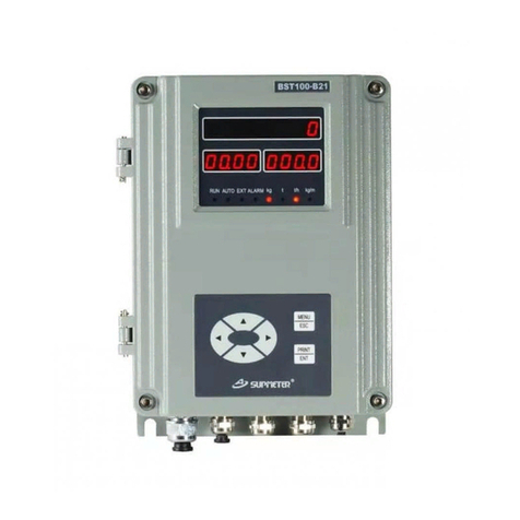
![Supmeter BST106-B60[A] User manual Supmeter BST106-B60[A] User manual](/data/manuals/1s/q/1sqb6/sources/supmeter-bst106-b60-a--manual.jpg)
Supmeter
Supmeter BST106-B60[A] User manual
Popular Controllers manuals by other brands

Federal Signal Corporation
Federal Signal Corporation SS2000+ ? Series Operation manual

Loctite
Loctite 2257357 operating manual

Emerson
Emerson Level-Trol 2500 Series instruction manual

YASKAWA
YASKAWA YRC1000 instructions

Siemens
Siemens HydroRanger 200 HMI operating instructions

Alpha IP
Alpha IP TD 61001 Series manual