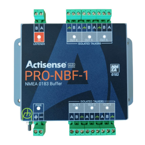
Actisense Pro Series User manual

Professional Type Approved
NMEA®0183 Buffer
Install/User Manual
Issue
Issue 1.06
Connect without limits

Contents
Company Information 4
Important Notices 5
Trademarks and Registered Trademarks 5
Fair Use Statement 5
Technical Accuracy 5
Product Registration 5
Product Guarantee 5
Product Disposal 5
Product Overview 6
Features 6
Example of a Typical PRO-NBF-1 Installation 6
Package Contents 6
Installation Warnings 8
Mounting the PRO-NBF-1 9
Bulkhead Mounting 9
DIN Rail Mounting 9
Connecting Power to the PRO-NBF-1 10
Figure 3 - Power Connection Diagram 10
Connecting to the PRO-NBF-1 Ports 11
Connecting an NMEA Talker 11
Connecting an NMEA Listener 11
Connecting an RS232 Device (PC) as a Talker 12
Connecting an RS232 Device (PC) as a Listener 12
Troubleshooting Guide 14
LED Indicators 14
Technical Support and the Returns Procedure 14
Technical Specications 15
PRO-NBF-1 Product Order Codes 16
PAGE INTENTIONALLY LEFT BLANK
© 2021 Active Research Limited © 2021 Active Research Limited

Company Information
Active Research Ltd
21 harwell Road
Poole, Dorset
UK, BH17 0GE
Telephone: +44 (0)1202 746682
Email: [email protected]
Web: www.actisense.com
Important Notices
The PRO-NBF-1 complies with the Electromagnetic Compatibility requirements according to EN60945:2002,
DNVGL-CG-0339:2019 & IACS UR E10 Rev7. The unit should always be used in conjunction with appropriately
approved shielded cable and connectors to ensure compliance. A declaration of conformity is available for
download at www.actisense.com. f the device to which this manual relates is to be installed within ve
metres of a compass, please refer to the‘Compass Safe Distance’ section in the ‘Technical Specications’
table.
Trademarks and Registered Trademarks
Actisense®and the Actisense logo are registered trademarks of Active Research Limited. All other trademarks are the
property of their respective owners.
The NMEA®name and NMEA logo are copyright held by the NMEA. All uses in this manual are by permission and no
claim on the right to the NMEA name or logo are made in this manual.
Fair Use Statement
The contents of this manual may not be transferred or copied without the express written permission of Active Research
Limited.
Copyright © 2021 Active Research Ltd. All rights reserved.
Technical Accuracy
To the best of our knowledge the information contained in this document was correct at the time it was produced.
Active Research Ltd cannot accept liability for any inaccuracies or omissions.
The products described in this manual and the specications thereof may be changed without prior notice. Active
Research Ltd cannot accept any liability for differences between the product and this document. To check for updated
information and specications please contact Active Research Limited.
Active Research Limited will not be liable for infringement of copyright, industrial property rights, or other rights of a
third party caused by the use of information or drawings described in this manual.
Product Registration
Please register your product via the online form www.actisense.com/support/prodreg.html.
Your product package includes a unit serial number. Your registration will assist Actisense Support to link your product
to your details, simplifying any future assistance you may require.
Product Guarantee
All Actisense products are provided with a 3 year guarantee as standard. To activate the 5-year guarantee offered
with this product please complete product registration online. If you suspect that the unit is faulty please refer to the
“Troubleshooting Guide” on page 14.
It is a requirement of the guarantee that all installations of electronic equipment follow the NMEA 0400 specication.
Any connection to a battery or power supply must meet the mandatory essential safety requirements that may be
imposed by local regulatory agencies.
Actisense products are intended for use in a marine environment, primarily for below deck use. If a product
is to be used in a more severe environment, such use may be considered misuse under the Active Research
Limited guarantee.
Product Disposal
Please dispose of this product in accordance with the WEEE Directive. The product should be taken to a registered
establishment for the disposal of electronic equipment.
© 2021 Active Research Limited
Professional Type Approved NMEA®0183 Buffer - PRO-NBF-1
© 2021 Active Research Limited
Page 4 Page 5

The professional Actisense NMEA Buffer (PRO-NBF-1) distributes up to six identical data streams from a single source.
Signals are buffered to ensure each receiver has the required voltage levels. Isolation on the input and each output
allows non-isolated devices to be connected safely. The device is Type Approved, enabling installation on vessels where
this is a requirement.
Features
• Works automatically with any serial protocol, including NMEA 0183
• Works automatically at any baud rate up to 115200 Baud
• Opto-isolation on the input meets the latest NMEA 0183 specication
• ISO-Drive™ provides galvanic isolation on the outputs to prevent ground loops
• Compatible with all NMEA 0183 versions without requiring conguration
• Inputs and outputs compatible with RS422 and RS232 devices
• Bulkhead Mount and optional DIN Rail Mount
• Pluggable screw terminals for quick and easy installation
• Amplication of weak input signals
• Rugged stainless steel housing suitable for harsh environments
• Metal housing acts as an RF Shield
• Diagnostic LEDs for Power, Input and Output operation
Product Overview
Package Contents
• 1 x PRO-NBF-1 with pluggable screw terminals.
Available Accessories
• Screwless Terminals
• Strain Relief Bracket kit
• DIN Rail Mount kit
PAGE INTENTIONALLY LEFT BLANK
© 2021 Active Research Limited
Professional Type Approved NMEA®0183 Buffer - PRO-NBF-1
© 2021 Active Research Limited
Page 6 Page 7

Bulkhead Mounting
Method:
Actisense recommends the PRO-NBF-1 is installed using DIN rail for the most secure installation.
However, the PRO-NBF-1 can be secured to a bulkhead using the four screw holes on either side of the PRO-NBF-1.
Mounting the PRO-NBF-1
All warnings and notices must be followed to ensure the correct operation of the PRO-NBF-1. Incorrect
installation may invalidate the guarantee.
It is highly recommended that all of the installation instructions are read before commencing the installation.
There are important warnings and notes throughout the manual that should be considered before the
installation is attempted.
Warning 1: Accuracy
The Actisense PRO-NBF-1 is designed to accurately transfer data from the input to its outputs. No data integrity checking
is performed by the PRO-NBF-1. Any incomplete, inaccurate or corrupt data received on the PRO-NBF-1 input will be
duplicated to the PRO-NBF-1 outputs. The accuracy of the data is dependant on the NMEA Talker or other source device
that generated the data.
Warning 2: Installation and Operation
This product must be installed and operated in accordance with the instructions provided. Failure to do so could result
in personal injury, damage to your boat and/or poor product performance.
Warning 3: Installation Code of Practice
When wiring the power supply to the PRO-NBF-1 ensure the isolation switch is off. Wiring the PRO-NBF-1 while the
connection is live may damage the PRO-NBF-1 and is in breach of the guarantee. Any connection to a battery or power
supply must meet the mandatory essential safety requirements that may be imposed by local regulatory agencies.
All wiring should be in accordance with the requirements of the NMEA 0400 installation specication.
Warning 4: Mounting Requirements
Select a at location to mount the PRO-NBF-1. Mounting on a contoured surface may cause damage to the case.
Do not mount the PRO-NBF-1 while the device is powered.
Do not mount the PRO-NBF-1 while the cable harness is connected.
Note that the terminals are pluggable for easy disconnection when mounting or removing the PRO-NBF-1.
Installation Warnings
DIN Rail Mounting
Method:
Install the DIN rail in the desired location.
Attach the PRO-NBF-1 to the DIN rail as shown in the diagrams below.
Ensure the PRO-NBF-1 sits ush against the DIN rail.
© 2021 Active Research Limited
Professional Type Approved NMEA®0183 Buffer - PRO-NBF-1
© 2021 Active Research Limited
Page 8 Page 9

Connecting to the PRO-NBF-1 Listener Port (INPUT)
The input to the PRO-NBF-1 is labelled ‘Listener’ and this is where the NMEA Talker should be connected:
• Connect the PRO-NBF-1 Listener A/+ to the positive data line of the NMEA Talker. When connecting RS232 or NMEA
0183 version 1 Talkers, this will be the Tx / data out of the Talker.
• Connect the PRO-NBF-1 Listener B/- to the negative data line of the NMEA Talker. When connecting RS232 or NMEA
0183 version 1 Talkers, this will be the ground / common of the Talker. Always check the manual for the correct
wiring.
Note: Only one NMEA Talker can be connected to the PRO-NBF-1 Listener (Input) ports.
Note: The NMEA Listener (Input) ports are fully isolated and is compatible with all versions of NMEA 0183 and with
RS422, RS232 and RS485 voltage levels.
Connecting to the PRO-NBF-1 Talker Port (OUTPUT)
The output to the PRO-NBF-1 is labelled ‘Talker’ and this is where the NMEA Listener should be connected:
• Connect the PRO-NBF-1 Talker A/+ to the positive data line of the NMEA Listener. When connecting RS232 or NMEA
0183 version 1 Listener, this will be the Rx / Data In of the Listener.
• Connect the PRO-NBF-1 Talker B/- to the negative data line of the NMEA Listener. When connecting RS232 or NMEA
0183 version 1 Talkers, this will be the ground / common of the Listener.
Care should be taken when creating this connection. It is only possible to wire B/- into GND thanks to Actisense ISO-
Drive technology providing protection. Consult the relevant User Manual if not using Actisense Products for wiring
instructions.
Connecting Power to the PRO-NBF-1
• The PRO-NBF-1 requires a power source providing between 10 and 35 Volts DC.
• The PRO-NBF-1 ‘+’ Terminal should be connected to the vessel power supply ‘+’ Terminal with the correctly rated
fuse (in accordance with NMEA 0400 Standard)
• The PRO-NBF-1 Negative ‘-’ Terminal should be connected to the vessels DC Ground Plate.
• The PRO-NBF-1 should only be used with standard negative ground DC systems.
NMEA 0183 Listener and Talker Designations
The NMEA have updated the NMEA 0183 specication to ensure a consistent naming convention is used for labelling
ports. The designation follows the same rules as used for Rx and Tx labelling but uses Talker and Listener instead.
The input / receiving (Rx) port will be labelled as a ‘Listener’ port.
The output / transmitting (Tx) port will be labelled as a ‘Talker’ port.
When a port is labelled ‘Listener’ it is an input and when it is labelled ‘Talker’ it is an output.
Input Output
Terminals
The PRO-NBF-1 comes with 2-way and 3-way screw connectors. Screwless terminals are available as an accessory.
PRO-NBF-1 connectors are pluggable, meaning they can be easily removed for quick and simple wire installation
without the need to unmount the PRO-NBF-1 from its installed location.
Screw Connector
3-way2-way
Screwless Connector (Supplied as an accessory)
Open the clamp inside the screwless connector by pressing down on the orange button with a small (2mm) at
headed screwdriver. This will allow the wire to be inserted. For best connections do not twist the wire strands.
Release the orange button to lower the clamp on to the wire strands for a secure termination.
© 2021 Active Research Limited
Professional Type Approved NMEA®0183 Buffer - PRO-NBF-1
© 2021 Active Research Limited
Page 10 Page 11

Connecting an RS232 Device (PC) as a Talker
A PC can be connected the same way as an RS232 type NMEA Talker.
• Connect the NBF-3 Listener A/+ to the Tx pin of the RS232 connector. (PIN 3)
• Connect the NBF-3 Listener B/- to the Ground pin of the RS232 connector. (PIN 5)
Connecting an RS232 Device (PC) as a Listener
A PC can be connected the same way as an RS232 type NMEA Listener.
• Connect the PRO-NBF-1 Listener A/+ to the Tx pin of the RS232 connector. (PIN 2)
• Connect the PRO-NBF-1 Listener B/- to the Ground pin of the RS232 connector. (PIN 5)
PAGE INTENTIONALLY LEFT BLANK
© 2021 Active Research Limited
Professional Type Approved NMEA®0183 Buffer - PRO-NBF-1
© 2021 Active Research Limited
Page 12 Page 13

Technical Specications
Troubleshooting Guide
First level PRO-NBF-1 diagnostics / fault nding can be performed by observing the LED behavior. The normal
behavior of the PRO-NBF-1 LEDs is described below. If the LEDs are not behaving as expected, this will indicate a fault
in either the device connected to the PRO-NBF-1, the wiring/connections, or the PRO-NBF-1 itself.
Name of LED and it’s behaviour If LED does not light
Power (Blue ‘PWR’) LED
Solid blue to indicate presence
of power.
• Ensure that the power terminal plug is correctly located and seated.
• Ensure that the wires are securely connected to the plug.
• Ensure that positive power and ground wires have been connected with the
correct polarity.
• Ensure that any external power fuse has not blown and that the external
power isolation switch is closed.
• Ensure that the power supply meets the Voltage and Current requirements
as dened in the Specications
Listener (Green ‘IN’) LEDs
Flashes on receipt of any data
• Ensure that the PRO-NBF-1 has power, refer to “Power (Blue ‘PWR’) LED”
above.
• Ensure that the (NMEA Talker) device connected to this input is powered and
is congured to output data.
• Ensure that the plug is correctly located and the wires are securely connected
to the plug, with the correct polarity.
• Ensure that two data wires are connected to the PRO-NBF-1 Listener
terminals. If the (NMEA Talker) device does not have a ‘negative’ data
connection/wire, connect its ground to the ‘B/-’ on the PRO-NBF-1 Listener
terminal instead.
Talker (Amber ‘OUT’) LEDs
Flashes on transmit of data
• Ensure that the PRO-NBF-1 has power, refer to “Power (Blue ‘PWR’) LED”
above.
• Ensure that the plug is correctly located and the wires are securely connected
to the plug, with the correct polarity.
• Ensure that the corresponding Green (Data IN) LED is lit to indicate that data
is being sent to the PRO-NBF-1.
• For PC Connections, Actisense NMEA Reader can be used to determine if
there is any data on the output.
Technical Support and the Returns Procedure
All installation instructions and any warnings contained in this manual must be followed before contacting Actisense
technical support. If the troubleshooting guide did not help resolve the problem and an error persists, please contact
Actisense Technical Support to help trace the issue before considering the return of the product. If the Actisense
support engineer concludes that the PRO-NBF-1 unit should be returned to Actisense, a ‘Return Merchandise
Authorisation’ (RMA) number will be issued by the support engineer.
The RMA number must be clearly visible on both the external packaging and any documentation returned with
the product. Any returns sent without an RMA Number will incur a delay in being processed and a possible
charge. Any cables originally supplied with the product are to be included in the returned box.
Technical Specication
All specications are taken with reference to an ambient temperature of 25°C unless otherwise specied.
All specications correct at time of print.
Power Supply
Input Supply Voltage 9 to 35V DC
Input Supply Current 150mA max @ 12V DC (all outputs @ full drive into 100Ω loads)
Input Protection Continuous reverse polarity and ESD protection
Power Indicator LED, Blue - Indicates unit is functioning correctly
Input Supply Connector Pluggable 2 way screw terminal, 5.08mm pitch (12 to 30 AWG)
NMEA 0183 Port - Listener & Talkers
Number of Listener / Input Ports One isolated NMEA 0183 Listener
Number of Talker / Output Ports Six isolated NMEA 0183 Talkers
Compatibility Fully NMEA 0183, RS422 & RS232 compatible. RS485 Listener compatible
Speed / baud rate 4800 to 115200 bps
Talker Output Voltage drive >= 2.2V (differential) into 100Ω
Talker Output Current drive 20mA max.
Talker Output Protection Short circuit and ESD
Talker Data Indicator LED, Orange (Flashes at data rate)
Listener Input Voltage Tolerance -15V to +15V continuous, -35V to +35V short term (<1 second)
Listener Input Protection Current limited, overdrive protection to 40V DC and ESD protection
Listener Data Indicator LED, green (Flashes to indicate valid input)
Connectors Pluggable 2/3-way screw terminals, 5.08mm pitch (12 to 30 AWG)
Isolation
NMEA 0183 Listener OPTO-Isolated, Hi-Pot tested to 1000V
NMEA 0183 Talker Uses IsoDrive™, Hi-Pot tested to 1000V
Mechanical
Housing Material 316 Stainless Steel
Dimensions 139mm (L) x 128mm (W) x 27mm (H)
Weight 335g
Mounting Bulkhead mount or DIN rail mount (DIN kit 1)
Approvals and Certications
EMC IEC 60945:2002-08, DNVGL-CG-0339:2019 & IACS UR E10 Rev7
Compass safe distance 600mm
Type Approval Certicate RINA
Operating Temperature -25 to +70°C
Storage Temperature -40 to +85°C
Maximum Relative Humidity (RH) 95% @ 55°C
Environmental Protection IP40
Guarantee 5 Years
© 2021 Active Research Limited
Professional Type Approved NMEA®0183 Buffer - PRO-NBF-1
© 2021 Active Research Limited
Page 14 Page 15

®
PRO-NBF-1 Product Order Codes
Product Dimensions:
Active Research Ltd
21 Harwell Road
Poole, Dorset
UK, BH17 0GE
Telephone: +44 (0)1202 746682
Email: [email protected]
Web: www.actisense.com
Part Number Description
PRO-NBF-1 1 OPTO input, 6 ISO-Drive outputs professional Type Approved Buffer
Accessory Description
DIN-KIT-1 Kit of 2 clips & 4 screws. Use with top hat (EN 50 022) or G section (EN 50 035) rails
A-CONPACK-
PNBF1 Pluggable Screwless Terminal pack for PRO-NBF-1
SRB-90 Kit of 2 x 90mm Stainless Steel Strain Relief Brackets
USBKIT-PRO USB To Serial Adapter for use with PRO range products
© 2021 Active Research Limited
Page 16
This manual suits for next models
1
Table of contents
Other Actisense Controllers manuals
Popular Controllers manuals by other brands

Controlli
Controlli Energon NR9001 Mounting instructions

REYNAERS
REYNAERS 062.8620 Installer manual

Ancona
Ancona PA-TM-WF01 installation instructions

IWAKI PUMPS
IWAKI PUMPS FDC-1 instruction manual

Sunforce
Sunforce BLUE SKY ENERGY IPN Remote Installation and operation manual

Western
Western WRM30 user manual

Ropex
Ropex CIRUS UPT-6010 operating instructions

Panasonic
Panasonic WRKT4504E Series Reference manual

AP
AP TC5-1N5FAB user manual

General Standards Corporation
General Standards Corporation PC104P-SIO4BX Hardware user manual

Toshiba
Toshiba P9 ASD Installation & operation manual

DPS Telecom
DPS Telecom NetGuardian LPG D-PK-NGLPG user manual