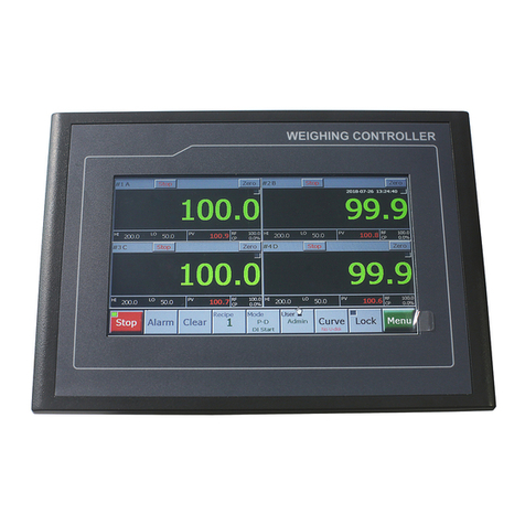
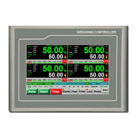
Supmeter BST106-M10 User manual

BST106-M10[FB] Weighing Controller
For: Ration Batching Scale with 4-material&2-speed Feeding
[Single-scale Mode & Four-scale Mode]
Operation Manual V5.0
Changsha Supmeter Technological Co.,Ltd.

1
Preface
Thank you very much for your purchase!
This manual covers safety precaution, technical specification, operation interface, installation&
connection, function&operation and so on. In order to make the product running at its best, please read this
manual in advance, and reserve it for the future reading.
The technology update, function enhancement and quality improvement may lead to some differences
between this manual and the physical product, please understand.
Without our authorization, the contents of this manual are not allowed to be copied and reproduced.
Main Features:
Suitable for Ration Batching Scale with 4-material&2-speed feeding [Single-scale Mode &
Four-scale Mode].
EMC design with high anti-jamming capability, suitable for industrial environment.
Cortex-A8 CPU with 600MHz Clock, 128M RAM and 128M Flash.
7”/10.2” Ultralight and ultrathin TFT touch screen with embedded weighing/control module.
Loadcell Interface
4 Loadcell ports. Max. Connection Quantity: 4×4 Loadcells (350Ω).
24-bit High-precision and high-speed ∑-△A/D conversion module with 1/1,000,000 internal
resolution and sampling frequency 800Hz.
Special anti-vibration digital filtering algorithm for ensuring the weighing stability and
accuracy when there is strong vibration on the load receptor, and the rapid response capability
when the weight signal changes.
I/O Interface
7 Definable normally open switch inputs [DI] and 18 definable normally open transistor switch
outputs [DO].
Optional ‘High/Low Speed Feed’ DOs for feeding control. Optional Low-speed Feeding
Modes: Continuous Feeding Mode and Inching Feeding Mode.
4 Definable analog signal AO[0~10V] for weight signal output or ‘High/Low Speed Feed’
control.
Digital Communication Interface
COM1[RS232]&COM2[RS485] for connecting Host IPC/PLC and LED Remote Display.
COM[RS232] for connecting RS232 Serial Printer.
USB1 for connecting USB mouse, downloading HMI software from U-disk and copying data
to U-disk.
Software Function
Manual Screen-locking/Screen-unlocking, Auto Screen-locking, Digital Setting&Calibration
and I/O Testing functions available.
Initial Zero Adjustment after Power-on, Auto Zero Tracking, Zero Fine Adjustment and Zero
Calibration functions available.
Load Calibration and Loss Calibration functions available.
10 Recipes for batching control.
Optional ‘Fall Value Auto Correction’ function.
Optional ‘Auto Pause for Deviation Alarm’, ‘Auto Pause while Gross Weight Upper Limit
Alarming’, ‘Manual Pause’and ‘Auto Re-feed’ functions.
Optional ‘Target Batch Control’ function [With Target Batch Count finished, the batching
process will stop automatically].
The Batch Records can be printed automatically.
Historical Batch Records, Totalizing Reports and Recipes can be queried and printed.
With the multitasking mode, the weighing&control process will not be interrupted by
parameter setting and the other operations.

2
Contents
1. SAFETY PRECAUTION.................................................................................................................4
2. TECHNICAL SPECIFICATION ....................................................................................................5
3. OPERATION INTERFACE ............................................................................................................6
3.1 OPERATION INTERFACE OF USER LOGIN................................................................................................6
3.2 MAIN OPERATION INTERFACE FOR APP1 SINGLE-SCALE MODE............................................................7
3.3 MAIN OPERATION INTERFACE FOR APP2 FOUR-SCALE MODE ..............................................................8
3.4 BUTTON OPERATION .............................................................................................................................9
3.5 DATA DISPLAY &QUICK SETTING.......................................................................................................10
3.6ALARM SIGN ....................................................................................................................................... 11
3.6.1 Alarm Message...........................................................................................................................11
3.6.2 Prompt Message .........................................................................................................................11
3.6.3 Error Message............................................................................................................................ 12
4. INSTALLATION&CONNECTION..............................................................................................13
4.1 INSTALLATION.....................................................................................................................................13
4.1.1 Outline Size............................................................................................................................... 13
4.1.2 Installation Angle ...................................................................................................................... 13
4.1.3 Installation Mode....................................................................................................................... 14
4.2 TERMINAL...........................................................................................................................................15
4.2.1 Terminal Diagram...................................................................................................................... 15
4.2.2 Power Supply Terminal ............................................................................................................. 15
4.2.3 Loadcell Terminal...................................................................................................................... 16
4.2.4 Digital Communication Terminal.............................................................................................. 17
4.2.5 Analog&Switch Signal Terminal............................................................................................... 18
4.3 DI/DO EX-FACTORY ASSIGNMENT......................................................................................................19
4.4 TYPICALAPPLICATION:APP1 SINGLE-SACLE MODE...........................................................................21
4.4.1 System Diagram for APP1 Single-sacle Mode.......................................................................... 21
4.4.2 DI/DO Connection for APP1 Single-Sacle Mode...................................................................... 22
4.5 TYPICALAPPLICATION:APP2 FOUR-SACLE MODE.............................................................................23

3
4.5.1 System Diagram A for APP2 Four-Sacle Mode without Mixing Bin........................................ 23
4.5.2 System Diagram B for APP2 Four-Sacle Mode with Mixing Bin............................................. 24
4.5.3 DI/DO Connection for APP2 Four-Sacle Mode ........................................................................ 25
5. OPERATION PROCEDURE ........................................................................................................26
6. FUNCTION&OPERATION ..........................................................................................................27
6.1 MAIN MENU INTERFACE .....................................................................................................................27
6.2 MAIN MENU FUNCTION ......................................................................................................................28
6.3 F1 SETTINGS .......................................................................................................................................29
6.3.1 Weighing Parameters................................................................................................................. 29
6.3.2 Calibration Parameters .............................................................................................................. 31
6.3.3 Setpoint Parameters................................................................................................................... 32
6.3.4 Working Mode Parameters........................................................................................................ 33
6.3.5 Timer Parameters....................................................................................................................... 36
6.3.6 Communication Parameters....................................................................................................... 39
6.3.7 Display Parameters.................................................................................................................... 40
6.4 F2 CALIBRATION.................................................................................................................................41
6.4.1 Static Calibration....................................................................................................................... 41
6.4.2 Loss Calibration ........................................................................................................................ 42
6.5 F9 I/OASSIGNMENT............................................................................................................................44
6.5.1 DO Assignment ......................................................................................................................... 44
6.5.2 DI Assignment........................................................................................................................... 47
6.5.3 AO Assignment.......................................................................................................................... 50
APPENDIXA. PRINT FORMATS ...................................................................................................52
APPENDIX B. REGISTER TABLE OF HOST-SLAVE MODBUS[ASCII/RTU]........................53
APPENDIX C. DATA FRAME FORMAT OF CONTINUOUS SENDING [ASCII]....................58

4
1. Safety Precaution
Lithium Battery Installation
A Lithium battery should be equipped in the product. If it is not allowed to be transported
together with the product because of embargo, please make a purchase according to the
model offered by us and install it by yourself.
Application environment
Make sure that this product works under the environment where is accord with the technical
specifications.
Do not open the shell before power-off.
Controller Protection
The product, as a low-voltage equipment, should be kept away from the high-voltage
equipments.
Scale Frame Protection
For avoiding bodily injury from electric shock accident and separating the loadcells from
strong interference, the scale frame should be grounded directly with the ground resistance
being less than 4Ω.
Cable Laying
Weighing signal, analog signal and communication signal cables should be laid in pipes, and
do not lay them together with power cables.
Power Supply
The power supply of the controller should be separated from the power supply of the driving
devices.
Please make sure that the inputted voltage is correct before power-on.
Environmental Protection
Before the Lithium battery equipped in the product being discarded, please insulate its
positive or negative pole, do not put it into fire.
While being discarded as worthless, the product should be processed lawfully as leady
industrial waste for environment protection.
Other Notes
The installation, wiring and maintenance should be operated by the engineers with the
relevant professional knowledge and safety operation ability.
Although being not described in this manual, the relevant safety operating procedures and
standards should be followed.

5
2. Technical Specification
Executing Standard
CMC GB/T 7724-2008《Electronic Weighing Meter》PRC National Standard.
OMIL R76: 2006《Non-automatic Weighing Instruments》International Recommendation.
Accuracy Grade: III.
Verification Accuracy: 0.02%.
Static Weighing Accuracy: 0.2%~0.5%.
Batching Accuracy: 0.2%~0.5%.
Structure&Configuration
7”/10.2” Ultralight and ultrathin TFT touch screen with embedded weighing/control module.
Cortex-A8 CPU with 600MHz Clock, 128M RAM and 128M Flash.
Display&Operation
16-bit Color screen with 800×480[7”] or 1024×600[10.2”] pixel and LED backlight.
Graphic display interface and touch operation.
Weight Display Range: -99,999~+999,999.
Scale Capacity: Setting Range 1~999,999.
Scale Division: Optional 1, 2, 5, 10, 20, 50.
Display Resolution: 1/100,000.
Weight Unit: Optional g, kg, t, lb[pound], oz[ounce], UserSet.
Decimal Point: Optional 0, 0.0, 0.00, 0.000.
Loadcell Interface
4 Loadcell ports. Max. Connection Quantity: 4×4 Loadcells (350Ω).
Excitation Voltage/Max. Current: DC5V, 250mA.
Signal Input Range: 0~12.5mV.
Output Sensitivity of Loadcell: 1.0~2.5mV/V.
24-bit ∑-△ADC with internal resolution 1/1,000,000.
Sampling Frequency: 800Hz.
Special Anti-vibration Digital Filtering Algorithm for precise weighing, stable display and rapid
response.
Zero Drift: ±0.1μV/℃RTI (Relative to Input).
Gain Drift: ±5ppm/℃.
Non-linearity: 0.005%FS.
Switch&Analog Signal Interface
7 Definable Normally Open Switch Inputs [DI].
18 Definable Normally Open Transistor Switch Outputs [DO]: DC24V, 500mA.
4 Definable Analog Signal Output [AO]: 0~10V/Max.50mA, Non-linearity: 0.05%FS.
Digital Communication Interface

6
COM1[RS232]&COM2[RS485] for connecting Host IPC/PLC and LED Remote Display.
COM[RS232] for connecting RS232 Serial Printer with Baud Rate ‘9600bps’, Parity Check ‘None’, 8
Data Bits and 1 Stop Bit.
USB1 for connecting USB mouse, downloading HMI software from U-disk and copying data to
U-disk.
Report Print
The Batch Records can be printed automatically.
Historical Batch Records, Totalizing Reports and Recipes can be queried and printed.
Operating Specification
Operating Voltage: DC24V±20%.
Max. Power Consumption: 10W.
7” Touch Screen
Outline Size: 226.5×163×36mm [W×H×D].
Window Size: 153.6×86.64mm [W×H].
Panel Cut-out Size: 215×152mm [W×H].
Weight: Approx. 0.72kg.
10.2” Touch Screen
Outline Size: 274×193×40mm [W×H×D].
Window Size: 220.8×132.9mm [W×H].
Panel Cut-out Size: 261×180mm [W×H].
Weight: Approx. 1.2kg.
Protection Level of Front Panel: IP65.
Operating Temperature: -25℃to + 4 5℃.
Storage Temperature: -30℃ to + 60℃.
Relative Humidity: Max. 85%RH.
3. Operation Interface
3.1 Operation Interface of User Login
Name
Operation
Note
【Login】
User Login.
Exfactory Passwords:
Operator: None.
Engineer: 0.
Administrator: 1.
Operation ‘
Main Menu / F5 User / Password / PSW
Set’ for Modifying Password.
【User Name】
After password inputted, the matching
User Name will be displayed.
Operator: User with lowest authorization.
Engineer: User with higher authorization.
Administrator: User with highest authorization.
【Operate】Enter ‘Main Operation Interface’. Operation ‘
Main Menu / F5 User / Password / Login
[Logoff]’for Re-login and Logoff.

7
3.2 Main Operation Interface forAPP1 Single-scale Mode
Parameter [906] ‘Main Display Style’= ‘0: ZQH’:
Parameter [906] ‘Main Display Style’= ‘1: GUI1’:

8
3.3 Main Operation Interface forAPP2 Four-scale Mode
Parameter [906] ‘Main Display Style’= ‘0: ZQH’:
Parameter [906] ‘Main Display Style’= ‘1: GUI1’:

9
3.4 Button Operation
Name Operation State Indicator Authorization
【Auto】Auto / Manual [Emergency Stop] switch. Green: Auto state.
Grey: Manual state.
All Users
【Start】Start. Green: Running state.
Grey: Stop state.
【Re-run】Clear Alarm & Recover Running.
【Last】Last Batch [Normal Stop].
Stop after the present batch finished. Flashing Red.
【Pause】Pause.
【E-stop】Emergency Stop.
【Alarm】
Alarm Query / Clear Alarm.
‘Auto/Pause’ state: Recover Running after
clearing alarm.
Red: Alarm state.
【Mat.】
Material Selection for Auto-Batching.
Mixer in Weighing Hopper
Running Selection
While High-speed Feeding [Only for Single-scale
Mode].
Green/Blue: Selected.
Grey: Unselected.
【Print】
Report Print:
[ Auto Print]: Print Batch Records.
[Total]: Print Totalizing Report.
[Recipe]: Print Working Recipe.
【Lock】
Screen-
locking: Locking/unlocking the operating
buttons of main display interface.
Auto Screen-locking: Refer to parameter [901].
Flashing Red: Locked.
Grey: Unlocked.
【Menu】Enter Main Menu.
【User】User Login. Display: Operator / Engineer / Admin.
【Zero】Zero Fine Adjustment [No Power-down
Protection]. Flashing green.
【High】Manual Start/Stop Mn High-speed Feeding.
Green: Working state.
【Low】Manual Start/Stop Mn Low-speed Feeding.
【Dump】Manual Start/Stop Dumping.
【MixbinDump】Manual Start/Stop Mixing Bin’s Dumping.
【Mn】Material Selection for Manual Operation.
【Clear】Clear Screen: Clear the display values of Feeding
Weight, Totalized Weight and Batch Count’. Engineer
Administrator

10
3.5 Data Display & Quick Setting
Name Description Authorization
Biggest Digits Real-time Weight / Material Mn’s Feeding Weight [Weight Unit].
[GROSS] Gross Weight.
[HI] Gross Weight Upper Limit Alarm.
[OL] Overload Alarm.
[CYCLES] Batch Count.
[▲]/HI Positive Deviation Alarm.
[▼]/LO Negative Deviation Alarm.
[TOTAL] Total Totalized Weight.
[RUN] Auto Running state.
[PAUSE] Pause state.
[ZERO] Gross Weight ≤Non-load Zero Range.
[STAB] Weight is stable.
[FED] Material Mn Feeding Ended.
[AU_FALL] ‘Fall ValueAuto Correction’Permission.
[ALL_FED] All Materials Feeding Ended.
[BAT_CON] ‘Target Batch Control’ is allowed. Refer to parameter [301] ‘ Target
Batch Control’and [203] ‘Target Batch’.
[BAT_FIN] Target Batch Finished.
[MIX]/[MIXING] The mixer is running.
[BELT] The mixing conveyor is running.
[RECIPE] ‘Working Recipe’Setting. All Users
[Mn TARGET] Mn Target Value.
[Mn FINAL] Mn Final Feeding Weight.
[SUM TARGET] The sum of the Target Values of all the materials selected for batching.
[SUM FINAL] The sum of the Final Feeding Weight of all the materials selected for
batching.
[CYCLES TARGET ]
[BAT. COUNT] Target Batch Count.
[CYCLES FINAL] Batch Count.
[Time] Date&Time.

11
3.6 Alarm Sign
3.6.1 Alarm Message
3.6.2 Prompt Message
Message Alarm Cause Solution
Gross Weight Upper
Limit Gross Weight ≥Upper Limit. Refer to parameter [204]-[207] ‘Gross Weight
Upper Limit’.
Deviation Alarm Positive Deviation Alarm.
Negative Deviation Alarm.
Refer to parameter [200] ‘Allowed Positive
Deviation’ and [201] ‘Allowed Negative
Deviation’.
Pause Alarm
For Deviation Alarm.
Refer to parameter [310] ‘
Auto Pause for
Deviation Alarm’.
It’s allowed to do ‘Manual SP3 Re-feed’ for
Negative Deviation Alarm.
Press DI button ‘Start / Clear Alarm’ to recover
running.
For Gross Weight Upper Limit
Alarm. After fault handling, press DI button ‘Start / Clear
Alarm’to recover running.
For Feeding Overtime Alarm.
Feeding Overtime Feeding Time≥T6. Refer to parameter [406] ‘T6
Max. Feeding
Time’.
Dumping Overtime Dumping Time≥T7. Refer to parameter [407] ‘T7 Max. Dumping
Time’.
Message Alarm Cause Solution
Target Batch
Finished
Alarm or Auto-stop with ‘Target
Batch Finished’.
Refer to parameter [203] ‘Target Batch’ and [301]
‘Target Batch Control’.
Last Batch It’s in the batch
ing process of the
last batch.
The message will disappear after the present batch
finished.
ZERO Invalid Over ‘Zero Fine Adjusting Range’. Refer to parameter [123]
‘Zero Fine Adjusting
Range’.

12
3.6.3 Error Message
Message Alarm Cause Solution
RAM Fault The chip RAM is damaged. Replace the chip RAM.
EEPROM Fault The chip EEPROM is damaged. Replace the chip EEPROM.
Parameter Error The chip EEPROM is damaged. Replace the chip EEPROM.
Weighing Signal
Error
Weighing signal reversed or not
connected. Connect the loadcell correctly.
ADC Fault The chip ADC is damaged. Replace the ADC module.
Over ADC Range
Weighing signal exceeds A/D
conversion range.
1. Check if the loadcell is connected.
2. Check if the capacity of loadcell is too small.
3. Check if the loading weight is too big.
Overload Alarm Gross Weight > (Scale Capacity + 9
× Scale Division).
1 . Check if the set value of parameter [102]
‘Scale Capacity’is reasonable.
2. Check if the loadcell is connected.
3. Check if the capacity of loadcell is too small.
4. Check if the loading weight is too big.
Internal Data-bus
Fault Please contact manufacturer.

13
4. Installation&Connection
4.1 Installation
4.1.1 Outline Size
4.1.2 InstallationAngle
Product Outline Size
W×H×D[mm]
Front Panel Size
W×H[mm]
Box Body Size
W×H [mm]
Panel Cut-out Size
W1×H1[mm]
7” 226.5×163×36 226.5×163 213×150 215×152
10.2” 274×193×40 274×193 259×178 261×180
The installation angle should be in the range of 0~30°.
Outline Size Panel Cut-out Size
H1
W1
7”

14
4.1.3 Installation Mode
Before installation the front end of the screw should be flat with the edge of the hook.

15
4.2 Terminal
4.2.1 Terminal Diagram
4.2.2 Power Supply Terminal
No. Pin Description
DC24V DC24V[±20%] Power Input Port
1 -DC Input -.
2 + DC Input +.
For separating the controller from the interference of the driving devices, the
DC24V power supply of the
controller should not be shared by the DI/DO.
LAN USB1 USB2
24V DC
+-
COM
1
2
DO
1 2 3 4 5 6 7 8 9 10 11
12
V- V+
COM2
DO
14
15
16
17
18
W
Tx
Rx
G
B-
A+
13
COM1
1 2 3 4 5 6 7
DI
1+
AO
2+
G 3+
4+
14 18 57
12
26913
3410
11
18 5712
269 3410
11
1 14
2 3 4 5 6 7 8 9 10
11
12
13
1 2 3 4 5 6 7 8 9 10
11
12
1-1+
E-
E+
3-
3+
P2-2+
E-
E+
4-
4+
P
LOADCELL

16
4.2.3 Loadcell Terminal
No. Pin Description
LOADCELL Loadcell Port
1 1- Weigher #1 Weighing Signal [mV] Input -.
2 1+ Weigher #1 Weighing Signal [mV] Input +.
3 E- Excitation Voltage -.
4 E+ Excitation Voltage + [DC5V].
5 3- Weigher #3 Weighing Signal [mV] Input -.
6 3+ Weigher #3 Weighing Signal [mV] Input +.
7 P Shield Ground.
8 2- Weigher #2 Weighing Signal [mV] Input -.
9 2+ Weigher #2 Weighing Signal [mV] Input +.
10 E- Excitation Voltage -.
11 E+ Excitation Voltage + [DC5V].
12 4- Weigher #4 Weighing Signal [mV] Input -.
13 4+ Weigher #4 Weighing Signal [mV] Input +.
14 P Shield Ground.

17
4.2.4 Digital Communication Terminal
No. Pin Description
7 W Special for manufacturer.
COM1 RS232 Digital Communication Port [Definable]
8 Tx Transmit Data [TXD].
9 Rx Receive Data [RXD].
10 G COM1 Signal Ground [GND].
COM2 Shield Ground [GND].
COM2 RS485 Digital Communication Port [Definable]
11 B- Data -.
12 A+ Data +.
COM RS232 Serial Printer Port [DB9]
2 RXD Receive Data.
3 TXD Transmit Data.
5 GND Signal Ground.
USB1 USB Data Copying Port / HMI Software Download Port / Mouse Port

18
4.2.5 Analog&Switch Signal Terminal
Name Pin Description
AO
0~10V Analog Output Port [Definable]
1 AO1+ Weigher #1 AO1 Output +.
2
AO2+
Weigher #2 AO2 Output +.
3 G AO Output -.
4
AO3+
Weigher #3 AO3 Output +.
5 AO4+ Weigher #4 AO4 Output +.
DI
Switch Signal Input Port [Valid with high-level input voltage 24V]
6 DI1 Switch Signal Input 1.
7
DI2
Switch Signal Input 2.
8 DI3 Switch Signal Input 3.
9
DI4
Switch Signal Input 4.
10 DI5 Switch Signal Input 5.
11
DI6
Switch Signal Input 6.
12 DI7 Switch Signal Input 7.
Name
Pin
Description
DO Transistor Switch Signal Output Port [Valid with high-level output voltage 24V]
1
V-
DC24V Input -.
2 DO1 Normally Open Contact Output 1.
3
DO2
Normally Open Contact Output 2.
4 DO3 Normally Open Contact Output 3.
5
DO4
Normally Open Contact Output 4.
6 DO5 Normally Open Contact Output 5.
7
DO6
Normally Open Contact Output 6.
8 DO7 Normally Open Contact Output 7.
9
DO8
Normally Open Contact Output 8.
10 DO9 Normally Open Contact Output 9.
11
DO10
Normally Open Contact Output 10.
12 DO11 Normally Open Contact Output 11.
13
DO12
Normally Open Contact Output 12.
14 V+ DC24V Input +.
1 DO13 Normally Open Contact Output 13.
2
DO14
Normally Open Contact Output 14.
3 DO15 Normally Open Contact Output 15.
4
DO16
Normally Open Contact Output 16.
5 DO17 Normally Open Contact Output 17.
6
DO18
Normally Open Contact Output 18.
Contact Capacity of Transistor Switch: DC24V, 500mA.

19
4.3 DI/DO Ex-factory Assignment
[*]: If need this DI function, the user can define it.
DI [Valid with high-level input voltage 24V]
No. Pin Signal Name Description
6 DI1 AUTO
[*]
Auto/Manual.
ON: Auto state.
OFF: Manual state / Emergency Stop.
7 DI2 START
Start.
‘Auto/Stop’state: Start.
In ‘Auto/Running’ process: Clear Alarm [Deviation Alarm
Acknowledge]
‘Auto/Pause’state: Clear Alarm & Recover Running.
OFF→ON→OFF.
8 DI3
LAST
Last Batch [Normal Stop].
OFF→ON→
OFF: Stop automatically after the batching
process of the present batch ended.
MIXER_START
[*]
Start Mixer.
OFF→ON→OFF.
9 DI4
DUMP_I
[*]
Manual Dump [#1-4].
ON: Manual Dump.
OFF: Stop.
MIXER_STOP
[*]
Stop Mixer.
OFF→ON→OFF.
10 DI5
BELT_START Start Mixing Conveyor.
OFF→ON→OFF.
PAUSE
[*]
Manual Pause.
OFF→ON→OFF.
11 DI6
BELT_STOP Stop Mixing Conveyor.
OFF→ON→OFF.
SP3_I
[*]
Manual SP3 Re-feed.
Valid at Auto-pause state with Mn’s Negativ
e Deviation
Alarm.
ON : Manual SP3 Re-feed.
OFF : Stop.
12 DI7 BELT_RDY
[*]
Mixing Conveyor Ready.
ON: Ready.
OFF: Not Ready.
Other manuals for BST106-M10
1
Table of contents
Other Supmeter Controllers manuals

Supmeter
Supmeter BST100-B11 User manual

Supmeter
Supmeter BST100-E11 User manual
![Supmeter BST106-B60[A] User manual Supmeter BST106-B60[A] User manual](/data/manuals/1s/q/1sqb6/sources/supmeter-bst106-b60-a--manual.jpg)
Supmeter
Supmeter BST106-B60[A] User manual

Supmeter
Supmeter BST100-E81 User manual

Supmeter
Supmeter BST106-M10 User manual

Supmeter
Supmeter BST106-M10(GH) User manual

Supmeter
Supmeter BST106-F19 User manual

Supmeter
Supmeter BST106-B60S(L) User manual
Popular Controllers manuals by other brands

Federal Signal Corporation
Federal Signal Corporation SS2000+ ? Series Operation manual

Loctite
Loctite 2257357 operating manual

Emerson
Emerson Level-Trol 2500 Series instruction manual

YASKAWA
YASKAWA YRC1000 instructions

Siemens
Siemens HydroRanger 200 HMI operating instructions

Alpha IP
Alpha IP TD 61001 Series manual