Surtek CSS02 Dimensions and installation guide

ATENCIÓN: lea, entienda y siga las instrucciones de seguridad contenidas en este
manual antes de operar esta herramienta.
WARNING: read, understand and follow the safety rules in this manual, before operating this tool.
CSS02
CARETA
ELECTRÓNICA
PARA SOLDAR
ELECTRONIC WELDING
HELMET
MANUAL DE USUARIO Y
GARANTÍA.
USER’S MANUAL AND WARRANTY

2
ENGLISHESPAÑOL
Safety Warnings
Features
Technical data
Operation instructions
Maintenance
Troubleshooting
Warranty policy
Advertencias de seguridad
Características
Especificaciones técnicas
Instrucciones de operación
Mantenimiento
Solucionador de problemas
Garantía
6
6
7
7
7
8
12
3
3
4
4
5
5
12
CONTENIDO CONTENT
SÍMBOLOS SYMBOLS
PELIGRO, ADVERTENCIA, PRECAUCIÓN:
Indica un riesgo personal o la posibilidad de
un daño.
Lea el manual de usuario: lea las instruccio-
nes contenidas en este manual.
DANGER, CAUTION, WARNING: indicates risk of
personal injury and/or the possibility of damage.
Read the user manual: read all the instructions in
this manual.

3
ESPAÑOL•Manual de usuario
CONOZCA SU HERRAMIENTA
PRODUCTO COMPLETO
1. Armazón de la careta.
2. Pin de ajuste de altura del arnés.
3. Perilla de ajuste para presión de arnés
4. Perilla de ajuste de distancia y ángulo del ar-
nés.
5. Ajuste de nivel de sombras.
6. Lente de la cubierta frontal.
7. Panel solar.
8. Placa fija.
9. Cartucho del filtro.
10. Filtro UV/IR.
FILTRO DE OSCURECIMIENTO AUTOMÁTICO
11. Perilla de control de retardo.
12. Perilla de control de sensibilidad.
13. LCD.
14. Panel solar.
15. Sensores del arco.
16. Filtro UV/IR.
ADVERTENCIAS DE SEGURIDAD
La careta electrónica/ solar con oscurecimiento
automático es ideal para la mayoría de las apli-
caciones de soldadura. El tiempo de cambio de
oscurecimiento automático de esta careta es
de 1/ 15,000 segundos al momento de que us-
ted comience a soldar. No importa el ajuste de
sombra, la protección UV/ IR está siempre estará
activado.
Los rayos del arco de soldadura pueden causar
lesiones en los ojos y quemar la piel.
*Antes de sol-
dar, inspeccione
la careta y el
filtro de auto-
oscurecimiento
para estar com-
pletamente
seguro de que
están ajustados
correctamente y
en buenas condiciones.
*Conserve limpios los sensores, la celda solar y el
filtro. Limpie el cartucho del filtro con agua y ja-
bón usando un trapo suave. No utilice solventes
o detergentes de limpieza abrasivos.
*No suelde por encima de su cabeza mientras
usa esta careta.
*Inspeccione el filtro frecuentemente. Reempla-
ce inmediatamente el lente o la tapa en caso de
rayaduras, grietas o golpes.
*Siempre utilice lentes de seguridad o gafas de
protección debajo de la careta para soldar, ade-
más de vestir ropa de protección para cuidar su
piel de radiación, quemaduras o salpicaduras.
CARACTERISTICAS
16
15
14
11 12
13

4
ESPECIFICACIONES TÉCNICAS
INSTRUCCIONES DE OPERACIÓN
1. Ajuste el diá-
metro del arnés
con la perilla
ubicada en la
parte trasera. La
perilla siempre
estará bloquea-
da hasta que se
le presione. Una
vez desbloquea-
da, gire hacia
la derecha para
apretar y hacia
la izquierda para
aflojar
2. Ajuste la altura encajando el pasador en el
orificio para asegurarlo firmemente en su lugar.
3. Para ajustar el ángulo de visión, afloje la pe-
rilla en ambos lados de la careta y cambie el
ángulo de bloqueo a la posición de inclinación
deseada (5 posiciones predeterminadas para se-
leccionar). Una vez que haya logrado el ángu-
lo deseado, apriete bien las perillas en ambos
lados. La careta podrá moverse hacia arriba,
pero no debe deslizarse hacia abajo mientras
esté en posición para soldar.
4. Para ajustar la distancia entre la cara del
usuario y el filtro de oscurecimiento automáti-
co, afloje las perillas en ambos lados de la ca-
reta hasta que la banda para la cabeza pueda
moverse hacia adelante y atrás libremente, en-
tonces coloque la banda en una de las 3 ranuras
según lo desee usted (La banda está posicionada
en la posición centro por defecto). Esto lo debe
realizar un lado a la vez y ambos lados deben
estar colocados en la misma posición para que
el filtro de oscurecimiento automático funcione
correctamente.
COMPROBACIÓN AUTOMÁTICA
Presione el botón “TEST” en cualquier lugar
para observar si cambia automáticamente al es-
tado oscuro y suéltelo para verificar que el filtro
regrese a su estado de luz.
CONTROL DE SOMBRA
Seleccione el nivel de sombra entre 9 y 13 ba-
sado en el proceso de soldadura que usted
vaya a utilizar, puede consultarlo en la “Tabla
guía de sombras”. La careta también puede ser
usada para proteger su rostro cuando esmerile.
El modo esmerilado previene que el lente del fil-
tro se auto oscurezca.
CONTROL DE SENSIBILIDAD
La sensibilidad puede ser ajustada a BAJA o
ALTA con el dial infinito. El ajuste en BAJA se
adapta al exceso de luz ambiental o con otra
máquina de soldar cerca. El ajuste ALTA se adap-
ta a la soldadura de bajo amperaje y soldadura
en área con poca luz, especialmente la soldadu-
ra con arco de argón de bajo amperaje. Las se-
lecciones entre ALTA y BAJA son adecuadas para
la mayoría de las operaciones de soldadura en
interiores y exteriores.
CONTROL DE RETARDO
Cuando cesa la soldadura, la ventana de visua-
lización cambia automáticamente de oscuro a
claro con un retraso preestablecido para com-
pensar. El tiempo de retardo se puede confi-
gurar en MIN (0.1 s) o MAX (1.0 s) con el dial
infinito. El retraso mínimo se adapta a soldadu-
ras cortas. El retardo máximo se adapta a la sol-
dadura de corriente pesada y reduce la fatiga
ocular causada por el arco. Las selecciones entre
MIN y MAX son adecuadas para la mayoría de
las operaciones de soldadura en interiores y ex-
teriores.
CSS02
ÁREA DE VISIÓN 92 X 42 mm
TAMAÑO DEL CARTUCHO 110 x 90 mm
ARCO DEL SENSOR 2
UV/IR PROTECCIÓN DIN 16
VISIÓN EN ESTADO CLARO DIN 4
VISIÓN EN ESTADO OSCURO
(SOMBRA VARIABLE) Sombra variable ex-
terna (9-13)
CONTROL DE SENSIBILIDAD Ajustable entre Bajo
– Medio – Alto
VELOCIDAD DE OSCURECIMIEN-
TO 1 / 15,000 s, de claro
a oscuro
TEMPERATURA DE OPERACIÓN -5ºC ~ + 55ºC
RETARDO DE OSCURECIMIENTO 0.1 - 1.0 s, ajustable
por dial infinito, de
claro a oscuro.
TIPO DE BATERÍA Celda solar y batería
de litio reemplazable
1 x CR2450
BAJO AMPERAJE TIG DC ≥ 10, AC ≥ 10
TEMPERATURA DE OPERACIÓN -5 °C a + 55 °C
TEMPERATURA DE ALMACENA-
MIENTO -20 °C a + 70 °C

5
ESPAÑOL•Manual de usuario
MANTENIMIENTO
REMPLAZO DEL LENTE DE LA CUBIERTA FRON-
TAL
Reemplace el lente de la cubierta frontal si está
dañado (agrietado, rayado, sucio o golpeado).
Retire el lente frontal de la cubierta frontal pre-
sionando los Interruptores de Bloqueo en la
parte inferior del Marco de Retención y extraiga
el marco y el Filtro de Oscurecimiento Automá-
tico. Saque el lente de la cubierta frontal y reti-
re cualquier película protectora antes de instalar
la nueva.
REMPLAZO DEL LENTE DE LA CUBIERTA INTE-
RIOR
Reemplace la lente de la cubierta interior si está
dañado (agrietado, rayado, sucio o golpeado).
Coloque el dedo o el pulgar en el hueco y flexio-
ne el lente de la cubierta interior hacia arriba
hasta que se libere de un borde. A continuación,
retire la película protectora antes de instalar un
lente nuevo.
REMPLAZO DE LA BATERÍA
Cuando el indicador de voltaje se torne rojo,
usted tiene que cambiar la batería. Gire las pla-
cas de la cubierta del filtro de oscurecimiento
automático y reemplace la batería antigua por
una batería de litio CR2032. Después de eso, co-
loque las cubiertas de la batería y gire para blo-
quear.
LIMPIEZA Y ALMACENAMIENTO
Mantenga los sensores, celdas solares y lentes
del filtro limpios. Limpie el filtro y la cubierta
de la careta mediante el uso de una solución de
agua y jabón, utilizando un paño suave. No uti-
lice solventes o detergentes de limpieza abrasi-
vos. Cambie el producto a “Modo Esmerilar” y
colóquelo en un lugar limpio y seco para su al-
macenamiento.
SOLUCIONADOR DE PROBLEMAS
PROBLEMAS POSIBLES
CAUSAS
SOLUCIÓN SUGE-
RIDA
Dificultad
para ver a
través del
filtro.
El plástico
protector en la
parte interna o
exterior no ha
sido removido
Remueva este plástico
Tapa de la
lente sucia
Limpie o reemplace la
tapa de la lente.
Lente del filtro
sucia
Limpie o reemplace la
lente del filtro.
El filtro no
se oscurece
cuando el
arco esta
funcionan-
do.
Está seleccio-
nado el modo
esmerilar
Ajuste el nivel de
sombras entre 9 y 13.
Los sensores
o el panel
solar están
atascados.
Asegúrese de que
el sensor o el panel
solar están expuestos
al arco de soldadura
sin bloqueos.
La sensibilidad
está en BAJA
Ajuste la sensibilidad
al nivel requerido.
Bajo voltaje de
las baterías de
litio.
Reemplace las bate-
rías de litio por unas
nuevas si el indicador
se torna rojo.
El filtro se
oscurece sin
el arco.
La sensibilidad
está en ALTA
Ajuste la sensibilidad
a un nivel requerido.
El filtro si-
gue oscuro
después de
soldar.
Está seleccio-
nado el nivel
de retardo en
MAX
Ajuste el nivel de re-
tardo a lo requerido.

6
SAFETY WARNINGS
The Solar-
Powered Au-
to-Darkening
Welding Helmet
is suitable for
most welding
applications.
This helmet’s
1/15,000-second
switch time au-
tomatically darkens the lens the moment you
start welding. No matter what shade the filter
is set to, the UV/IR protection is always present.
ARC Rays can injure eyes and burn skin
Before welding, always inspect helmet and au-
to-darkening filter (ADF) to be sure they are fit-
ted properly and in good condition.
Keep the sensors, solar cell and filter lens clean.
Clean the filter cartridge using a soap water
solution and soft cloth. Do not use solvents or
abrasive cleaning detergent.
Do not weld in the overhead position while us-
ing this helmet.
Inspect the filter lens frequently and immedi-
ately replace any scratched, cracked, or pitted
filter lens or cover lenses.
Always wear safety glasses or goggles under the
welding helmet, and protective clothing to pro-
tect your skin from radiation, burns and spatter.
FEATURES
KNOW YOUR TOOL
WHOLE PRODUCT
1. Helmet shell.
2. Headgear Height Adjusting Pin.
3. Headgear Diameter Adjusting Knob.
4. Headgear Angle & Distance Adjusting Knobs.
5. Shade No. Adjusting.
6. Front Cover Lens.
7. Solar Panel.
8. Fixed Plate.
9. Press card.
10. UV/IR Filter.
ADF GX-400S
11. Delay Control Knob.
12. Sensitivity Control Knob.
13. LCD.
14. Solar Panel.
15. Arc Sensors.
16. UV/IR Filter.
16
15
14
11 12
13

7
ENGLISH•User's Manual
TECHNICAL DATA
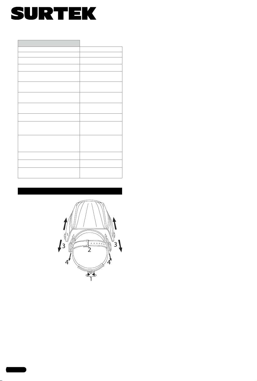
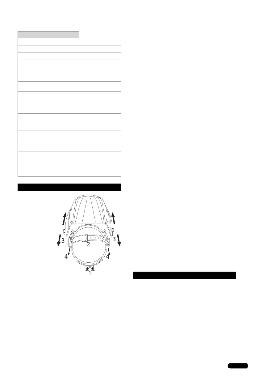
OPERATION INSTRUCTIONS
1. Adjust the
headgear dia-
meter with the
twist knob on
the back. The
knob is locked
until pushed in.
Once unlocked,
twist clockwise
to tighten and
counterclockwi-
se to loosen.
2. Adjust the
height by snap-
ping the pin into
the hole to lock securely in place.
3. To adjust the viewing angle, loosen the knob
on both sides of the helmet and change angle
locker to the desired tilt position (5 selection
and positioned in the middle by default). Once
achieving the desire angle, tighten the knobs
until snug. The helmet should still swing up, but
it should not drift downward when in place for
welding.
4. To adjust the distance between the user’s face
and ADF, loosen the knobs on both sides of the
helmet until the headband can move back and
forth freely, reposition the headband at one of
the 3 slots as desired (The headband is positio-
ned in the middle by default). This should be
done one side at a time and both sides should
be located at the same position for proper auto-
darkening filter operation.
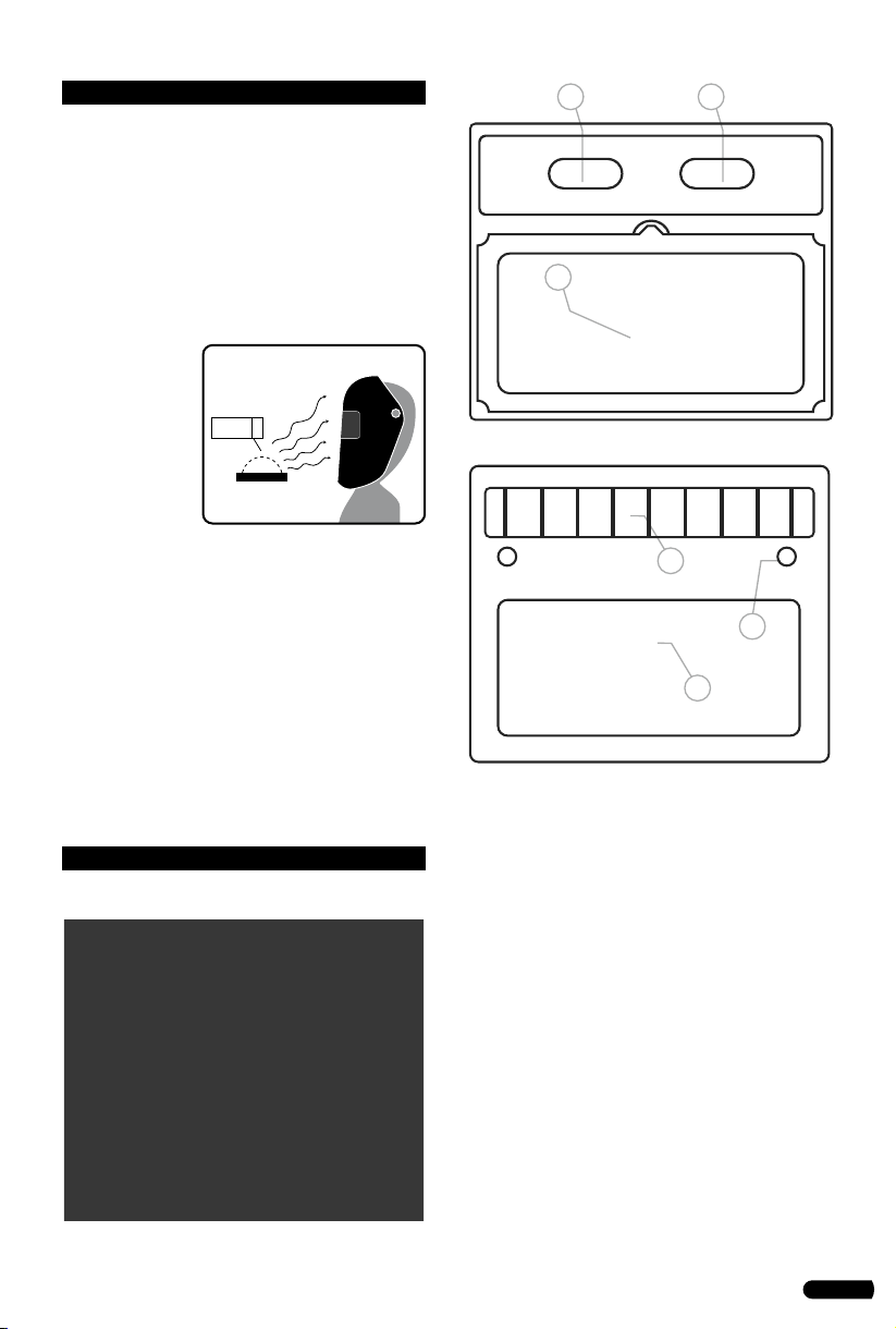
SELF-CHECK
Press the TEST Button anywhere to see if it au-
tomatically switches to dark state and release it
to check that the filter returns to the light state.
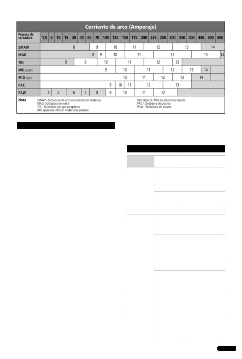
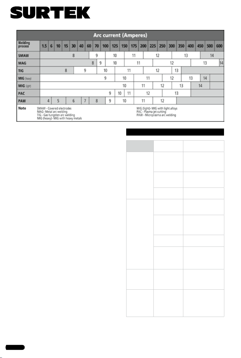
SHADE CONTROL
Select the shade 9 to 13 based upon the welding
process you will use by consulting the “Shade
Guide Table”. The welding helmet can also be
used to protect the face when grinding. Grind
mode prevents filter lens from auto-darkening.
SENSITIVITY CONTROL
The sensitivity can be set to LOW or HIGH by
using the infinitely dial knob. The LOW setting
suits excess ambient light or with another wel-
ding machine close by. The HIGH setting suits
low amperage welding and welding in areas
with low light conditions, especially low am-
perage argon arc welding. Selections between
LOW and HIGH are suitable for most of indoor
and outdoor welding operations.
DELAY CONTROL
When welding ceases, the viewing window au-
tomatically changes from dark back to light but
with a pre-set delay to compensate. The delay
time can be set to MIN (0.1 sec) or MAX (1.0 sec),
by infinitely dial knob inside the cartridge. The
minimum delay suits spot or short welds. The
maximum delay suits heavy current welding
and reduces eye fatigue from the arc. Selections
between MIN and MAX are suitable for most of
indoor and outdoor welding operations.
MAINTENANCE
FRONT COVER LENS REPLACEMENT
Replace the front cover lens if it is damaged
(cracked, scratched, pitted or dirty). Remove the
old front cover lens by pressing two Lock Swit-
ches at the bottom of the Retaining Frame and
pull the frame and ADF out. Take the old front
cover lens out, and remove any protective film
before installing the new one.
INSIDE COVER LENS REPLACEMENT
Replace the inside cover lens if it is damaged
(cracked, scratched, pitted or dirty). Place your
CSS02
VIEWING AREA 92×42mm
CARTRIDGE SIZE 110×90mm
ARC SENSOR 2
UV/IR PROTECTION UP to shade DIN 16 at
all times
LIGHT STATE DIN 4 (Grind)
DARK STATE External variable sha-
de, DIN9-13
SENSITIVITY CONTROL Low-Mid-High adjus-
table
SWITCH TIME (LIGHT TO DARK) 1/15,000 s, from Light
to Dark
DELAY CONTROL (DARK TO
LIGHT) 0.1-1.0S, by infinitely
dial knob, from Dark
to Light
POWER SUPPLY Solar cell and
1×CR2450 non-re-
placement lithium
battery
TIG AMP RATING DC≥10, AC≥10
OPERATING TEMPERATURE -5°C to +55°C
STORING TEMPERATURE -20°C to +70°C

8
finger or thumb into the recess and flex the insi-
de cover lens upwards until it releases from one
edge. Then remove any protective film before
installing the new one.
BATTERY REPLACEMENT
When low voltage indicator turns red, you have
to change batteries. Rotate cover plates on the
ADF, and replace the old battery by CR2032
lithium battery. After that, put on cover plates
of battery and rotate to lock.
CLEANING AND STORING
Keep the sensors, solar cell and filter lens clean.
Clean filter cartridge and helmet shell by using a
soapy water solution and soft cloth. Do not use
solvents or abrasive cleaning detergent. Switch
the product to Grind Mode and put it in a clean,
dry location for storage.
TROUBLESHOOTING
Problems Possible
causes
Suggested solu-
tions
Difficult to
see through
filter.
Protective film
on front/inside
cover lens not
removed.
Clean or replace front
cover lens.
Front/inside
cover lens
dirty.
Clean or replace
front/inside cover
lens.
Filter lens
dirty. Clean filter lens.
Filter does
not darken
when arc is
struck.
Grind mode
selected.
Select Weld Mode
and adjust Shade
from 9 to 13.
Sensors or
Solar Panel
blocked.
Make sure sensors
or solar panel are
exposed to weld arc
without blocking.
Set Sensitivity
to LOW.
Adjust sensitivity to
required level.
Low Voltage
of lithium
battery.
Replace with new
lithium battery if
indicator turns red.
Filter
darkens
without
arc.
Set sensitivity
to HIGH.
Adjust sensitivity to
required level.
Filter
remains
dark after
welding.
Set delay to
MAX.
Adjust sensitivity to
required level.

9
Manual de usuario • User’s manual
Notas / Notes

10
Notas / Notes

11
Manual de usuario • User’s manual
Notas / Notes

12
CSS02
URREA HERRAMIENTAS PROFESIONALES S.A.
DE C.V. Warranties this product for a period of 10
years in its parts, components and manual labour
against any manufacture defect from the purchas-
ing date.
Purchase date: ____/____/____
Product:____________________
Brand:______________________
Model:______________________
______________________________
Distributor seal and signature
Sold and Imported by:
URREA HERRAMIENTAS PROFESIONALES S.A. DE
C.V. Carretera a El Castillo, km 11.5, C.P. 45680,
El Salto, Jalisco, México. R.F.C. UHP900402Q29.
Terms:
In order to make warranty effective you must pres-
ent the product along with the warranty properly
filled and signed to an authorized distributor or
service center.
Present the invoice or ticket with official registra-
tion info of the trade from where the product was
purchased. The guarantee is effective as of the date
of purchase stated on the invoice or ticket; or with
the distributor’s stamp (with delivery date in this
policy).
URREA HERRAMIENTAS PROFESIONALES S.A.
DE C.V. Will cover the transportation cost related
to the warranty.
This warranty is not applicable in the follow-
ing cases:
· When the product has not been used according to
normal conditions or natural wear of its parts.
· When the product has not been used according
with this user’s manual instructions.
· When the product has been fixed or modified by
unauthorized or unqualified person.
URREA HERRAMIENTAS PROFESIONALES S.A.
DE C.V. garantiza este producto por el termino de
10 años en sus piezas, componentes y mano de obra
contra cualquier defecto de fabricación a partir de
la fecha de entrega.
Fecha de venta: ____/____/____
Producto: ___________________
Marca: ______________________
Modelo: ____________________
______________________________
Sello y firma de distribuidor
Comercializado e Importado por:
URREA HERRAMIENTAS PROFESIONALES S.A. DE
C.V. Carretera a El Castillo, km 11.5, C.P. 45680,
El Salto, Jalisco, México. R.F.C. UHP900402Q29.
Condiciones:
Para hacer efectiva la garantía deberá presentar
el producto junto con la póliza de garantía debi-
damente firmada y sellada por el establecimiento
donde la adquirió, en cualquiera de los centros de
servicio autorizados.
Presentar la factura o ticket con datos fiscales del
comercio de donde se adquirió el producto. La ga-
rantía cuenta a partir de la fecha de la nota o factu-
ra de compra o el sello con fechador del distribuidor
(con fecha de entrega en esta póliza).
Los gastos de transportación que se deriven del
cumplimiento de la garantía serán cubiertos por:
URREA HERRAMIENTAS PROFESIONALES S.A.
DE C.V.
Esta garantía no será valida en los siguientes
casos:
· Cuando el producto haya sido utilizado en condi-
ciones distintas a las normales o al desgaste natural
de sus partes.
· Cuando el producto no haya sido operado de
acuerdo al instructivo de uso que lo acompaña.
· Cuando el producto haya sido alterado o reparado
por personas no autorizadas.
ESPAÑOL
PÓLIZA DE GARANTÍA
ENGLISH
WARRANT POLICY
Table of contents
Languages:
Popular Welding Accessories manuals by other brands

FRONIUS
FRONIUS Robacta Reamer operating instructions

Telwin
Telwin TIGER XL instruction manual

Miller Electric
Miller Electric Millermatic 185 owner's manual

Jegs
Jegs 81544 installation instructions

Abicor Binzel
Abicor Binzel Air-blast and injection unit operating instructions

Abicor Binzel
Abicor Binzel ROBO Compact W600 Operating instruction