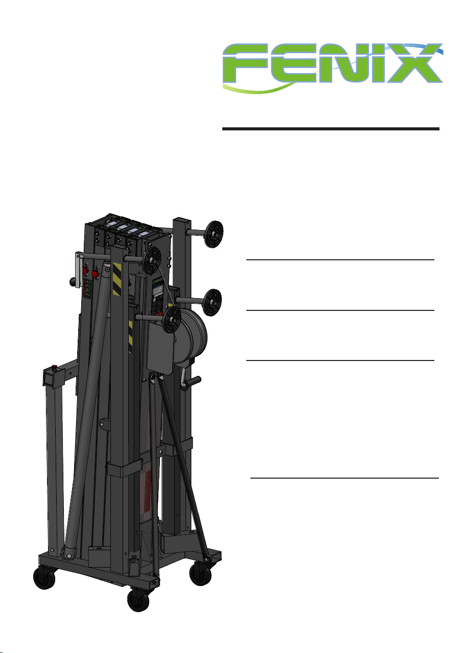
Fenix HERCULES 6.5 PLUS User manual

HERCULES 6.5 PLUS
HERCULES 6.5 PLUSHERCULES 6.5 PLUS
Nº de serie:Nº de serie:
Serial No.:
Instrucciones
Instructions
LIFTING TOWERS
Fabricante:
Manufacturer:
FENIX Stage, S.L.U.FENIX Stage, S.L.U.
Avda. de los Trabajadores, 24
Horno de Alcedo
46026 - Valencia (Spain)
Tel.: +34 96 125 08 55
www.fenixstage.comwww.fenixstage.com

22
C22.053G CERTIFICATE
Page 1 of 1
Certificate date: 01/12/2022
Issued to:
FENIX STAGE, S.L.U.
Avda. de los Trabajadores, 24
Horno de Alcedo –46026 - Valencia - Spain
The Inspector that signs this certificate has done the report nº 12245.22G for the revision of the manufacturer
documentation and machines design assessment, based on:
El Inspector que firma el presente certificado ha realizado el informe nº 12245.22G de revisión de la
documentación de fabricante y la evaluación del diseño de máquina, basado en:
•Directive 2006/42/CE on machinery that establish “Essential health and safety requirements relating
to the design and construction of machinery”/ Directiva 2006/42/CE relativa a las máquinas y que
establece los requisitos de seguridad y salud que se aplican en el diseño y construcción de máquinas.
•DGUV Rule 115-002 Staging and Production Facilities for the Entertainment Industry (regulation
17&18) / Norma DGUV 115-002 Instalaciones de montaje y producción para la industria del
entretenimiento (reglamento 17&18)
•DIN 56950-3:2015-12 & DIN EN 17206:2022-02
NAME: Lifting tower /torre de elevación
MARK: FENIX REFERENCE / TYPE / MODELO HERCULES 6.5 PLUS
Description/
descripción:
Lifting tower HERCULES 6.5 PLUS has been designed to vertically raise structures and lighting and
sound equipment to different heights / La torre elevadora HERCULES 6.5 PLUS ha sido diseñada
para elevar verticalmente estructuras y equipos de iluminación y sonido a diferentes alturas.
•Model properties / propiedades:
•Maximum height / altura máx: 6,50 m.
•Minimum height / altura mín: 1,69 m.
•Maximum load / carga máx: 500 kg.
• Material: AL Si 6106 / T6/ AL Si 6106 / T6
•Cable: galvanized steel EN12385-4. Max. load 2870kg, strength quality 1770 N/mm2,
diameter 6mm, composition 7x19+0 / acero galvanizado EN12385-4. Carga máx 2870kg,
Resistencia a la torsion 1770 N/mm2, diámetro 6mm, composición 7x19+0
•Open base area / área de la base abierta: 2,22x 2,07 m.
•Area of the base closed / área de la base cerrada: 0,52 x 0,62 m.
•Weight / peso: 198kg.
•Winch / cabestrante: 1150 kg Maximum Load with automatic load retention brake / 1150
kg de carga máxima con freno automático de retención de la carga
Each lifting tower has to be supplied with an EC declaration of conformity, including serial number and date of manufacturing.
To comply with DGUV Rule 115-002, for some event or production, an inspection done by an expert could be required before
start up / Cada torre elevadora debe suministrarse con una declaración CE de conformidad, que incluya el número de serie y la
fecha de fabricación. Para cumplir con DGUV Rule 115-002, para algún evento o producción, se debe requerir una inspección
realizada por un experto antes de la puesta en marcha
Based on reviewed documents, the inspector certifies that the machine COMPLIES with all minimal design
dispositions of the regulations applied / Con base en los documentos revisados, el inspector certifica que la máquina
CUMPLE con todas las disposiciones mínimas de diseño de la normativa aplicada.
In Bergondo at, December 01, 2022
Alejandro Balsa Campos
Industrial Engineer
Expert in Industrial Safety

33
DECLARATION OF CONFORMITY
FENIX STAGE S.L.U.
Adress: Avda. de los Trabajadores, 24 - Horno de Alcedo - 46026 - Valencia (Spain)
Phone/fax: +34 96 125 08 55 / +34 96 125 13 05
VAT No.: ESB-91423046
We declare at our exclusive liability the conformity of the product:
Name:
Model:
Description:
to which this declaration refers as per the following regulations: CE 2006/42/EG,
Person empowered to compile the technical le and authorised represntative:
Mª Julia Niza del Rio
LIFITNG TOWER
HERCULES 6.5 PLUS
Maximum height: 6,50m.
Minimum height: 1,69m.
Maximum load: 500kg.
Working area: 2,22 x 2,07m.
Weight: 198kg.
Winch: 1.150kg
Número de serie / Serial number
Fecha / Date

Partes comprobadas Conclusiones
Verificación fábrica
Fecha Verificador Firma
Partes comprobadas Conclusiones
Verificación UVV
Partes comprobadas Conclusiones
Fecha Verificador Firma
Primera verificación experto
Verificación experto (4º año)
Verificación experto (1 por año)
Partes comprobadas Conclusiones
Fecha Verificador Firma
Partes comprobadas Conclusiones
Fecha Verificador Firma
2
2
2
3
2
4
2
5
2
6
2
7
DGUV Rule 115-002
DGUV 17&18
DGUV Rule 115-002
DGUV 17&18
DGUV Rule 115-002
DGUV 17&18
DGUV Rule 115-002
DGUV 17&18
DGUV Rule 115-002
DGUV 17&18
DGUV Rule 115-002
DGUV 17&18

55
EXPLICACIÓN NORMA BGV C1 / EXPLANATION BGV C1 REGULATION
NORMA DGUV V17/18. Explicación
DGUV V17/18 (antes BGVC1) es una norma
que regula los elementos de escenario y pro-
ducción en la industria del entretenimiento.
Los equipos de elevación y rigging son parte
de esta norma y cubren estructuras y otros
elementos técnicos. Adoptar la norma DGUV
V17/18 es totalmente voluntaria (excepto en
Alemania) pero su adopción se requiere ge-
neralmente por compañías aseguradoras y de
hecho se está convirtiendo en una norma en
la industria.La aplicación de esta norma sobre
las torres elevadoras es vital debido a que, en
teatros, escenarios, etc., se usan para par mo-
ver cargas sobre artistas, personal técnico etc.,
y en algunos casos sobre espectadores, repre-
sentando un riesgo potencial de caída.
NORMA DGUV V17/18. Campos de aplica-
ción
Esta norma está orientada de dos maneras:
Por un lado, las torres elevadoras adoptan di-
seños y materiales con el objeto de conseguir
un alto grado de seguridad en magnitudes ta-
les como carga soportada, equilibrio, resisten-
cia a la fricción, etc. Así, las torres elevadoras
FENIX certicadas DGUV V17/18, aseguran
al usuario que han pasado estrictos controles
durante su diseño, elección de materiales o ve-
ricaciones de carga y esfuerzo. Por otro lado,
con el n de conseguir un funcionamiento
óptimo con estas unidades, es recomendable,
además de un uso responsable de la unidad
(cumpliendo unas normas básicas como son
obedecer la carga máxima soportada o su
equilibrio), un mantenimiento periódico el
cual debe ser llevado a cabo por técnicos ex-
pertos, comprobando el buen estado del cable
de acero y cabrestante, el funcionamiento de
los pasadores de seguridad y el plegado/des-
plegado del sistema completo de perles.
Todos los test mencionados solo son obligato-
rios en aquellos países con regulación especí-
ca en la materia, aplicada mediante regulacio-
nes o leyes. Como fabricantes, recomendamos
pasar todos los test con el objetivo de prevenir
cualquier daño y asegurar un buen funciona-
miento de los sistemas de elevación.
DGUV V17/18 NORM REGULATION. Ex-
planation
DGUV V17/18 is a norm that regulates the
stage and production elements in the enter-
tainment industry. Liing equipment and ri-
gging are part of this norm and cover struc-
tures and other technical elements. Adopt
DGUV V17/18 is totally voluntary (except in
Germany) but its adoption is required by in-
surance companies and indeed is becoming a
norm in the industry e application of this
norm on lier towers is vital because, in thea-
ters, stages, etc.., are used to move loads above
artists, technical sta, etc... and in some cases,
above viewers, representing a potential risk
of fall.
NORM DGUV V17/18. Fields of application
is standard is oriented in two ways:
On the one hand, liing towers adopt designs
and materials to achieve a high degree of safe-
ty in quantities such as supported load, equili-
brium, resistance to friction, etc. us, FENIX
liing towers DGUV V17/18 certied assure
the user that they have passed strict controls
during design, choice of materials or load
checks and eort. On the other hand, in order
to achieve an optimal performance with these
units, it is recommended, apart from a res-
ponsible use of the unit, (meeting basic norms
such as obey the maximum load or balance), a
periodic maintenance, which must be carried
out by expert technicians, checking the condi-
tion of the steel cable and winch, the functio-
ning of the security pins and the folding/un-
folding of all sections.
All the above tests are only mandatory in tho-
se countries with specic regulations on the
matter, applied through regulations or laws.
As manufacturers, we recommend passing all
tests in order to prevent
damage and ensure proper operation of P.A.
li systems.

66
ÍNDICE
1.- INTRODUCCIÓN 7
2.- DATOS GENERALES 7
2.1.- Datos técnicos 7
2.2.- Normativa de aplicación 7
3.- NORMAS DE SEGURIDAD 8
4.- INSTRUCCIONES DE USO 9
5.- MANTENIMIENTO 10
6.- RIESGOS ESPECÍFICOS 10
7.- SISTEMAS DE PREVENCIÓN 11
INDEX
1.- INTRODUCTION 12
2.- GENERAL DATA 12
2.1.- Technical data 12
2.2.- Applicable regulations 12
3.- GENERAL SAFETY RULES 13
4.- HOW TO USE 14
5.- MAINTENANCE 15
6.- SPECIFIC RISKS 15
7.- PREVENTION SYSTEMS 16

77
ESPAÑOL
1. INTRODUCCIÓN
El presente manual de instrucciones ha sido
realizado en conformidad con los requisitos
de la Directiva de Máquinas CE 2006/42/EG.
El manual de instrucciones representa par-
te integrante de la torre elevadora, debe ser
consultado antes, durante y después de la
puesta en marcha de la torre así como cada
vez que se considere necesario, respetando su
contenido en todas y cada una de sus partes.
Solamente de este modo se podrán alcanzar
los objetivos fundamentales que se han esta-
blecido en la base de este manual como son
prevenir riesgos de accidentes y optimizar lo
máximo posible las prestaciones de la torre
elevadora.
En el marco de dicho manual se han cuida-
do minuciosamente los aspectos correspon-
dientes a la seguridad y a la prevención de
accidentes en el trabajo durante la utilización
de la máquina destacando las informaciones
que son de mayor interés para el usuario.
ATENCIÓN: ANTES DE UTILIZAR LA
TORRE ELEVADORA,
LEA ATENTAMENTE ESTE MANUAL
2. DATOS GENERALES
2.1. Datos técnicos:
Denominación: TORRE ELEVADORA
Modelo: HERCULES 6.5 PLUS
Características técnicas:
Altura máxima: 6,50m.
Altura mínima: 1,69m.
Carga máxima: 500kg.
Carga mínima: 25kg.
Material: Aluminio según AL Si 6106 / T6.
Área de la base abierta: 2,22 x 2,07m.
Área de la base cerrada: 0,52 x 0,65m.
Peso: 198kg.
Cabestrante: 1.150kg de carga máxima con
freno automático de retención de la carga.
Cable: Acero galvanizado según EN 12385-4.
Carga máxima cable: 2.870kg.
Resistencia a la torsión cable: 1.770N/mm².
Diámetro cable: 6mm.
Composición cable: 7x19+0.
Sistema de seguridad por péndulo interno
más gatillo externo en tramos.
Anclaje de las patas por gatillos de seguridad.
Nivel de burbuja para ajustar posición verti-
cal de la torre.
Descripción del equipo:
La torre elevadora HERCULES 6.5 PLUS
ha sido diseñada para levantar estructuras y
aparatos de iluminación y sonido en sentido
vertical a diferentes alturas.
Ha sido probada por personal capacitado
habiendo superado todas las inspecciones de
funcionamiento, carga máxima y dimensio-
nes.
Empresa: FENIX Stage, S.L.U.
Dirección: Avda. de los Trabajadores, 24
Horno de Alcedo - 46026 - Valencia (España)
2.2.- Normativa de aplicación
- Directiva de máquinas 2006/42/CE.
- DGUV Rule 115-002
- DGUV 17&18
- EN 12385-4:2008-06.
- DIN EN 10305-3:2010-05.

88
ESPAÑOL
3. NORMAS GENERALES DE SEGURIDAD
- La torre elevadora es un elemento industrial diseñado para la elevación de cargas en sentido
vertical, NUNCA se debe utilizar como plataforma elevadora de personas.
- Colocar la torre elevadora sólo en supercies duras y planas, vericando que está en posi-
ción vertical. Nunca utilice cuñas ni elementos extraños para equilibrar la torre elevadora.
- Comprobar que las patas están correctamente montadas y sujetas por sus pasadores retene-
dores de seguridad.
- Nunca se debe elevar una carga sin antes vericar que está correctamente apoyada y cen-
trada en los soportes elevadores adecuados, de forma que el peso de la carga sólo actúe en
sentido vertical.
- No se debe sobrepasar la capacidad de carga máxima indicada en la etiqueta de característi-
cas de la torre elevadora y en este manual de instrucciones.
- Si existe posibilidad de viento fuerte o en ráfagas, coloque la torre elevadora en suelo rme
y asegúrelo con la ayuda de tirantes.
- Nunca je un tirante sobre un vehículo ni cualquier otro elemento que pueda desplazarse.
- No usar escaleras encima de la torre elevadora ni apoyarlas en él para realizar ningún tipo
de trabajo.
- Tenga cuidado con todo tipo de salientes por encima de la torre elevadora como cornisas,
balcones, letreros luminosos, etc. Es muy importante evitar la presencia de cables por debajo
de la altura de trabajo de la torre elevadora.
- Nunca se debe desplazar la torre elevadora si ésta se encuentra con la carga elevada. No es
aconsejable realizar ningún tipo de movimiento, ni tan siquiera pequeños ajustes de posicio-
namiento.
- Nunca utilizar la torre elevadora sobre ninguna supercie móvil o vehículo.
- Antes de utilizar la torre elevadora, vericar el estado del cable, éste no debe presentar rotura
de hilos o aplastamiento. No usar NUNCA cables defectuosos y en caso de duda cambie el
cable. Sólo utilice cable de acero según describe este manual.
- Fijar la manivela cuando la carga esté elevada.
- La carga mínima para un funcionamiento del freno sin problemas es de 25kg. Sin esta carga
mínima el freno no actuará.
- No engrasar ni lubricar el mecanismo de freno del cabestrante. Los discos de freno, han sido
engrasados con una grasa especial resistente al calor y la presión. No deben ser utilizados
otros productos para evitar inuir negativamente en el funcionamiento del freno.
- Para el transporte de la torre elevadora hay que bajar todos los tramos.

99
ESPAÑOL
4. INSTRUCCIONES DE USO
1. Colocar la torre elevadora sobre una super-
cie plana y rme en su emplazamiento de tra-
bajo.
2. Sacar las patas (H) de su soporte para trans-
porte (C) liberando el pomo de plástico (V)
y estirar de la pata (H) hacia arriba. Sacar los
brazos de apoyo frontales (O) de la pletina de
transporte (D).
3. Insertar las patas (H) en sus alojamientos de
trabajo (G) comprobando que quedan sujetas
por los gatillos de seguridad (K). Las patas lar-
gas, delante, bajo la carga.
4. Para poder colocar correctamente los brazos
de apoyo frontales (O) en sus puntos de ancla-
jes (P), deberá ajustar el plato de apoyo (J) de
la pata delantera, girando la manivela (I) de la
varilla reguladora. Colocar los pasadores de se-
guridad (M y N).
5. Ajustar la torre elevadora utilizando los pla-
tos de apoyo (J) girando la manivela (I) de la
varilla reguladora hasta que quede nivelada,
observando el nivel de burbuja estabilizador
(Y) de la base.
6. Poner los brazos de carga (E) en posición ho-
rizontal y asegurar con el gatillo de seguridad.
7. Colocar la carga que se va a elevar lo más
cerca posible de la torre elevadora. No separar
innecesariamente el equipo de sonido del cuer-
po de la torre elevadora para evitar una sobre-
carga. Ver g. 2 (pág. 17). Seguir instrucciones
de carga. Ver g. 3 (pág. 17).
8. Colocar sobre los brazos de carga (E) los ac-
cesorios AC-584 y AC-585 en el caso de volar
un equipo de sonido con jación central por
uno o dos puntos de volado. Ver g. 4 (pág.
17). En el caso de que el bumper tenga cuatro
anclajes perimetrales, se recomeienda utilizar
los accesorios AC-582 y AC-583 que permiten
levantar el equipo de sonido desde cuatro pun-
tos. Ver g. 5 (pág. 17).
9. Elevación: Para elevar los perles hay que
seguir un orden concreto. El primer perl que
hay que subir siempre será el más alejado del
cabestrante. Liberar el gatillo de seguridad (A)
en posición abierta (T) y girar la manivela del
cabestrante (B) en el sentido de las agujas del
reloj elevando la carga hasta la posición de-
seada. Inmediatamente después, mover el ga-
tillo de seguridad (A) en posición cerrada (S),
hasta que haya llegado al nal del tramo, y así
sucesivamente entre las distintas posiciones de
cada uno de los perles, hasta llegar a la altura
deseada. En el caso de que el gatillo esté duro
y sea difícil de sacar, hay que realizar un peque-
ño juego con el cabestrante hasta encontrar la
posición exacta donde se libere el gatillo y se
pueda sacar cómodamente. En ningún caso se
deberá tirar con fuerza de ninguno de los ga-
tillos. En caso de no elevar la torre elevadora
hasta su altura máxima, se recomienda subir
todos los perles proporcionalmente acorde a
la altura, y no únicamente uno de ellos.
10. En caso de usar la torre elevadora al aire
libre, existe el riesgo de vientos, para lo cual se
ha previsto de dos argollas laterales de jación
(L) situadas en la parte superior del segundo
perl, donde deberán jarse los tensores que
serán anclados a lugares rmes y seguros (nun-
ca sobre un vehículo o cualquier otro elemento
A
O
NM
B
VC
L
D
E
X
G
Y
T
U
S
J
I
HP
K

1010
ESPAÑOL
que pueda desplazarse). A partir de una ve-
locidad de 30km/h es imprescindible bajar la
torre elevadora.
11. En caso de que la torre elevadora se que-
de bloqueada en algún proceso del descenso,
hay dos opciones para intentar liberarla. La
primera siempre será tratar de elevar todos
los perles al máximo para así intentar des-
enredar el cable y desbloquear la torre eleva-
dora. La otra opción será si el problema es
debido a que el péndulo se haya engravado
en alguno de los perles. En este caso, la so-
lución será liberarlo mediante un golpe seco,
utilizando a ser posible, una llave allen en
L, o en su defecto cualquier destornillador.
Introducir la llave allen en la ranura inferior
del perl (R) que se haya quedado atascado
y golpear el péndulo con un martillo, inten-
tando desbloquearlo y liberar la torre eleva-
dora.
12. Descenso: Para bajar los perles hay que
seguir el orden contrario. El primer perl
que hay que bajar siempre será el más cer-
cano al cabestrante. Para liberar los gatillos
de seguridad (A) hay que elevar ligeramen-
te la carga con el cabestrante. En la posición
normal de trabajo, el peso de la carga impide
liberar los gatillos de seguridad (A). Una vez
liberado el gatillo de seguridad (A), mover
hasta la posición abierta (T) realizando el
paso (U), girar ligeramente la manivela del
cabestrante (B) en el sentido contrario a las
agujas del reloj. Inmediatamente después,
volver a colocar el gatillo de seguridad (A) en
posición cerrada (S), hasta el nal del tramo.
Repetir el mismo paso sucesivamente hasta
que quede completamente plegada a su altu-
ra mínima.
13. Para el transporte hay que bajar todos los
perles y colocar los gatillos de seguridad
(A) en posición cerrada (S). Exceptuando el
carro (X) que se quedará jado arriba con el
gatillo de seguridad (A) y con los brazos de
carga (E) orientados hacia abajo, jando así
el carro (X) para no sufrir bloqueos del pén-
dulo. Sacar los brazos de apoyo frontales (O)
de sus puntos de anclaje (P) y colocarlos en
su pletina de transporte (D) jándolos con
los pasadores de seguridad (M y N). Meter
las patas (H) en su soporte para transporte
(C) ajustando los pomos de plástico (V).
5. MANTENIMIENTO
1. Comprobar periódicamente el estado del
cable. Si un cable presenta rotura de hilos o
aplastamiento, debe ser sustituido inmedia-
tamente por otro nuevo. No utilizar la torre
elevadora con cables en mal estado. Utilizar
solamente cable de acero galvanizado según
EN 12385-4. Carga máxima cable: 2.000kg.
Resistencia a la torsión del cable: 1.770N/
mm². Diámetro cable: 6mm. Composicion
cable: 6x19+1.
2. La torre elevadora se suministra completa-
mente engrasada de fábrica. No obstante, se
recomienda engrasar periódicamente según
el uso, la corona dentada del cabestrante, la
rosca de la manivela y los tramos.
ATENCIÓN:
NO ENGRASAR NI LUBRICAR EL
MECANISMO DEL FRENO
Los discos de freno, han sido engrasados con
una grasa especial resistente al calor y la pre-
sión. No deben ser utilizados otros productos
para evitar inuir negativamente en el fun-
cionamiento del freno. No es necesario en-
grasar los discos de freno.
3. La torre elevadora HERCULES 6.5 debe
ser comprobada por un experto como míni-
mo una vez al año de acuerdo con su utili-
zación.
4. Solamente deben utilizarse piezas de re-
puesto originales para garantizar una con-
tinuada seguridad de uso. El usuario pierde
todos los derechos de garantía, si incorpora
otros repuestos que no sean originales o lleva
a cabo cualquier modicación en el produc-
to.
5. Para solicitar cualquier repuesto, contacte
con el fabricante o con un distribuidor auto-
rizado dentro de su territorio.

1111
ESPAÑOL
6. RIESGOS ESPECÍFICOS
Fallo del sistema de freno
Puede producirse por deciencias en el siste-
ma de frenado o por una mala instalación. Si
deja de funcionar puede provocar un riesgo
importante de pérdida de control de la mer-
cancía elevada y originar golpes y/o contu-
siones sobre los usuarios o golpes sobre los
materiales que se encuentren próximos a la
torre.
Pérdida de estabilidad
Si se coloca la torre sobre un terreno incli-
nado o sobre una supercie que no sea com-
pletamente lisa existe el riesgo de pérdida de
estabilidad lo que daría lugar generalmente a
un vuelco de 90º con riesgo de lesiones gra-
ves para los operarios.
Caída de objetos a distinto nivel
Como elemento de elevación, su trabajo en
altura hace que haya un riesgo importante
de caída a diferente nivel de los objetos ele-
vados, bien por fallo de los mecanismos de
sujeción, desgaste de piezas, suciedad, etc.
bien por utilización incorrecta de la torre (Ej:
para elementos por encima de la carga máxi-
ma permitida). El descenso brusco del mate-
rial elevado supone un elevado riesgo para el
operario.
Golpes y/o contusiones por objetos
Este riesgo tan sólo en contadas ocasiones
se traduce en accidente para el operario que
conduce la operación, dada su situación du-
rante el proceso de elevación; el riesgo de gol-
pes por el elemento sobreelevado puede más
bien afectar a personas que deambulen o ten-
gan su puesto de trabajo en zonas cercanas a
la torre elevadora.
Su origen puede ser debido a pérdida de es-
tabilidad, mal funcionamiento de elementos
estructurales, mal funcionamiento de siste-
mas de seguridad, sistemas de sujeción, etc.
7. SISTEMAS DE PREVENCIÓN
Sobre fallo del sistema de freno
Disponer de cabestrante conforme a las nor-
mas mencionadas en la directiva de seguri-
dad DGUV Rule 115-002, DGUV 17&18,
especialmente DIN EN ISO 12100:2011-03 y
DIN EN ISO 12100-1:2004-04.
Sobre pérdida de estabilidad
El mantenimiento de la estabilidad de la to-
rre elevadora debe realizarse básicamente
con las siguientes medidas:
• Profesionalización, adiestramiento, forma-
ción y concienciación del riesgo a los usua-
rios de las torres.
• Dotación de diferentes dispositivos de se-
guridad y consejos por parte del fabricante,
para reforzar su estabilidad como por ejem-
plo:
- Pasadores de seguridad que jan la torre
una vez elevada.
- Nivel de burbuja para facilitar el ajuste ver-
tical.
- Marcado de la carga máxima que puede ele-
var la torre.
- Especicación de la pendiente máxima a la
que pueden acceder las torres de forma se-
gura.
Sobre caída de objetos a distinto nivel, gol-
pes y/o contusiones con objetos
El riesgo de caída de objetos a distinto ni-
vel puede prevenirse con la utilización de
elementos de seguridad homologados, por
ejemplo, un gatillo de seguridad que je el
tramo interior de la torre en su posición de
trabajo, de forma que el cable no soporta la
carga y se garantiza la imposibilidad de una
caída. En caso de rotura de cable, actúa el
freno automáticamente. Por otra parte, si los
elementos de acero están zincados se protege
el conjunto de la oxidación y la corrosión.
También se pueden minimizar estos riesgos
con un adecuado mantenimiento de la torre
elevadora. El usuario deberá hacer inspeccio-
nes periódicas de los elementos de seguridad
y realizar las reparaciones necesarias en caso
de detectar deciencias.
Asimismo, se pueden reducir las consecuen-
cias de estos riesgos limitando la zona de
acceso a la torre elevadora y con adecuada
formación del personal.
Otras consideraciones
Este equipo no emite más de 80 dB.

1212
ENGLISH
1. INTRODUCTION
is instruction manual has been draed
in accordance with the requirements of the
Machinery Directive CE 2006/42/EG. e
instruction manual is an integral part of the
liing tower to be consulted before, during
and aer tower’s start-up, likewise whenever
deemed necessary, respecting the contents
for each and all the parts thereof.
is is the only way to achieve the basic ob-
jectives established in the manual’s base such
as preventing accident risks and the maxi-
mum possible optimisation for the liing
tower features.
is manual has taken extreme care regar-
ding safety and accident prevention at work
while using the machine, highlighting infor-
mation of particular interest to the user.
ATTENTION: BEFORE TO USING THE
LIFTING TOWER,
READ THIS MANUAL CAREFULLY
2. GENERAL DATA
2.1. Technical Data:
Name: LIFTING TOWER
Model: HERCULES 6.5 PLUS
Technical characteristics:
Maximum height: 6,50m.
Minimum height: 1,69m.
Maximum load: 500kg.
Minimum load: 25kg.
Material: Aluminium AL Si 6106 / T6.
Open base area: 2,22 x 2,07m.
Closed base area: 0,52 x 0,65m.
Weight: 184kg.
Winch: 1.700kg maximum load with auto-
matic load retention brake.
Cable: Galvanized steel under EN 12385-4.
Maximum load cable: 2.870kg.
Torsion resistance cable: 1.150N/mm².
Diameter cable: 6mm.
Composition cable: 7x19+0.
Fixation of tower sections to working height
with safety pins.
Leg anchorage with safety pins.
Bubble level to adjust tower’s vertical posi-
tion.
Equipment description:
Liing tower HERCULES 6.5 PLUS has been
designed to vertically raise structures and
lighting and sound equipment to dierent
heights.
Tested by skilled personnel having passed all
the operating, maximum load and dimen-
sion inspections.
Company: FENIX Stage, S.L.U.
Address: Avda. de los Trabajadores, 24
Horno de Alcedo - 46026 - Valencia (Spain)
2.2. Applicable regulations
- Directiva de máquinas 2006/42/CE.
- DGUV Rule 115-002
- DGUV 17&18
- EN 12385-4:2008-06.
- DIN EN 10305-3:2010-05.

1313
ENGLISH
3. GENERAL SAFETY RULES
- e liing tower is an industrial element designed to raise loads vertically, it must NEVER
be used as a platform elevator for people.
- Only place the liing tower on rm at grounds checking it is in vertical position. Do not
use wedges or any strange elements to balance the hoist.
- Check legs are correctly assembled and secured by their safety pins.
- Never raise a load without rst checking it is correctly supported and centred on the appro-
priate liing tower supports, so the load only acts vertically.
- Never surpass the maximum load capacity indicated on the liing tower characteristics label
and on this instruction manual.
- If there is a likelihood of strong wind or gusts, place the liing tower on the ground and
secure it with the aid of straps.
- Never x a strap over a vehicle or any other element which might move.
- Never use a ladder over the liing tower or lean against it for any kind of work.
- Beware of any kind of projection above the liing tower like cornices, balconies, luminous
signs, etc. It is very important to avoid the presence of cables below the liing tower’s working
height.
- Never move the liing tower when the load is raised. It is inadvisable to make any kind of
movement, even small positioning adjustments.
- Never use the liing tower over any mobile surface or vehicle.
- Before using the liing tower, check the cable’s state, which must not present any broken
threads or compression. NEVER use defective cables and change cable if in doubt. Only use
steel cable as described on this manual.
- Fix the lever when the load is raised.
- Minimum load for braking function without problems is 25kg. Brake will not function
without this minimum load.
- Neither grease nor lubricate the winch brake mechanism. Braking disks were greased with a
special heat and pressure resistant grease. No other products must be used to prevent negative
inuence on brake functioning.
- All sections of the liing tower must be lowered to transport it.

1414
ENGLISH
4. HOW TO USE
1. Place the liing tower over a rm and at
surface on its working place.
2. Remove the outriggers (H) from their trans-
port supports (C) by releasing the plastic knob
(V) and pull the outrigger (H) up. Remove the
front support braces (O) from its transport
support (D).
3. Insert the outriggers (H) into their working
position (G) checking that they are xed by the
safety pins (K). e longest outriggers must be
placed at the front, under the load.
4. In order to properly x the front support
braces (O) in their anchoring supports (P), ad-
just the support plate (J) of the front outrigger
by turning the crank (I) of the adjusting rod.
Insert safety pins (M & N).
5. Adjust the liing tower using the support
plates (J) by turning the crank (I) of the regula-
ting rod until it is level, checking the stabilizing
bubble level (Y) located at the base.
6. Place the forklis (E) in horizontal position
and secure them with the safety pins.
7. Put the load as close to the liing tower as
possible. Do not unnecessarily separate the
sound system from the liing tower body to
avoid overloading. See g. 2 (page 17). Follow
loading instructions. See g. 3 (page 117).
8. Place on the forklis (E) the accessories
AC-584 y AC-585 in case of ying a line array
system with central anchoring by either one or
two hanging points. See g. 4 (page 17). If the
line array’s bumper has four hanging points, it
is recommended to use the accessories AC-582
and AC-583 which enable to y the line array
system from four hanging points. See g. 5
(page 17).
9. Elevation: To li the proles, a specic order
must be followed. e rst prole to be raised
will always be the one located furthest from the
winch. Release the safety pin (A) in open posi-
tion (T) and turn the winch handle (B) cloc-
kwise, liing the load until the desired height.
Immediately aerwards, close the safety pin
(A) in position (S), until the end of the section
has been reached. Go on successively to the
dierent positions of each of the proles, until
the desired height is reached. In case the pin is
hard to pull out, a small number of movements
should be made with the winch until founding
the right position where the pin is released and
can be pulled out comfortably. Under no cir-
cumstances any of the pins should be pulled
with force. In case of the liing tower does not
need to be raised to its maximum height, it is
recommended to raise all the proles propor-
tionally according to the height, and not only
one of them.
10. When using the liing tower outdoors, the
risk of wind is prevalent, for which there are
two xing side rings (L) in the upper part of
the second prole, where safety cables must be
attached and xed on a secure and rm surface
(never on a vehicle or anything that can move).
When wind speed exceeds 30km/h, it is man-
datory to bring down the liing tower.
A
O
NM
B
VC
L
D
E
X
G
Y
T
U
S
J
I
HP
K

1515
ENGLISH
11. In case the liing tower gets blocked at
any point during lowering process, there are
two options to try to unlock it. e rst will
always be to raise all proles to its maximum
to try to untangle the cable and release the
liing tower. e other option will be if the
problem is due to the pendulum gets stuck in
one of the proles. In this case, the solution
will be to release it by a sharp knock, using
if possible, an allen key in L, or any screw-
driver. Put the allen key in the lower slot of
the prole (R) that has been stuck and hit the
pendulum with a hammer, trying to unlock
it and release the liing tower.
12. Lowering: To lower the proles, follow
the opposite order. e rst prole to be
lowered will always be the one located clo-
sest to the winch. To release the safety pins
(A), the load must be lied slightly with the
winch. In the normal working position, the
weight of the load prevents the safety pins
(A) from being released. Once the safety pin
(A) is released, move it to the open position
(T), by doing (U) step. en turn the winch
handle (B) slightly counterclockwise. Imme-
diately aerwards, move again the safety pin
(A) to closed position (S), until the end of
the section. Repeat the same steps successi-
vely until it is completely folded to its mini-
mum height.
13. For the liing tower transport, it is neces-
sary to bring down all proles and place the
safety pins (A) in closed position (S). With
the exception of the carriage (X), which will
remain xed at the top with the safety pin (A)
and the forklis (E) pointing down, securing
the carriage (X) to avoid the block of the
pendulum. Remove the front support braces
(O) from its anchoring support (P) and pla-
ce them to their transport support (D) xing
them with the safety pins (M & N). Place the
outriggers (H) in their transport support (C)
and retighten the plastic knob (V).
5. MAINTENANCE
1. Periodically check cable status. If the cable
seems to have broken cable wires or crushing,
replace immediately with a new one. Never
use the liing tower with cables in bad con-
ditions. Only use galvanized steel under EN
12385-4. Maximum load cable: 2.000kg. Tor-
sion resistance cable: 1.770N/mm². Diameter
cable: 6mm. Composition cable: 6x19+1.
2. e liing tower is supplied fully greased
from factory. Nevertheless, the crown gear of
the winch, to the threaded bar of the stabili-
ser outriggers and the proles, because of its
use periodical greasing is recommended.
WARNING:
DO NOT GREASE OR LUBRICATE
BRAKING MECHANISM
Braking disks were greased with a special
heat and pressure resistant grease. No other
product must be used to prevent negative in-
uence on brake functioning.
3. Liing tower HERCULES 6.5, must be
checked by an expert a minimum of once a
year as per its use.
4. Only original spare parts must be used to
ensure continued safe use. e user loses all
guarantee rights if spare parts other than the
originals are incorporated or modies the
product in any way.
5. To request any spare part, contact the
manufacturer or an authorised distributor
within your territory.

1616
ENGLISH
6. SPECIFIC RISKS
Braking system failure
May occur due to braking system decien-
cies or bad installation. If it stops working
it could cause a serious risk due to the rai-
sed load being out of control and may injure
users or hit materials next to the tower.
Loss of stability
If the tower is placed on a sloping ground or
a surface that is not completely at, there is a
risk of losing stability which would lead to a
90º overturn with risk of serious injuries for
workers.
Objects dropping to a dierent level
As an elevation equipment and due to its
working height, there is a serious risk of
raised objects dropping to a dierent level,
either due to securing mechanism failure,
part wear, dirt, etc., or incorrect use of the
liing tower (E.g.: for goods over the maxi-
mum load allowed). Sudden drop of raised
goods implies a serious risk for the worker.
Knocks and/or contusions due to objects
is risk only occasionally causes an accident
to the worker running the operation due to
his location during the elevation process; the
risk of knocks from a raised element is more
likely to aect people walking by or whose
workplace is next to the liing tower.
Its origin may be due to a loss of stability,
malfunctioning of structural elements, safety
systems, securing systems, etc.
7. PREVENTION SYSTEMS
About braking system failure
Equip with winch complying with regula-
tions metioned in the DGUV Rule 115-002,
DGUV 17&18, directive, specially DIN EN
ISO 12100:2011-03 and DIN EN ISO 12100-
1:2004-04.
About loss of stability
Maintenance of liing tower stability must
basically be as per the following measures:
• Professionalization, training and risk
awareness of liing tower users.
• Equip with dierent safety devices and ad-
vices from the manufacturer to reinforce sta-
bility, as:
- Safety pins which secure the liing tower
once raised.
- Bubble level to help vertical adjustment.
- Maximum load specication that the liing
tower can raise.
- Maximum slope specication which the lif-
ting tower can access safely.
About objects falling to a dierent level,
knocks and/or contusions with objects
e risk of objects falling to a dierent level
can be prevented by using homologated safe-
ty elements, e.g., a safety pin which xes the
inner prole of the liing tower in its wor-
king position, so the cable does not support
load and guaranteeing the impossibility of a
drop. In the event of cable breakage, the bra-
king system will act automatically. Further-
more, if steel elements have been zinc coated
it protects the entire unit from oxidation and
corrosion.
ese risks can also be minimised with co-
rrect liing tower maintenance. e user
must perform periodical inspections on sa-
fety elements and make the necessary repairs
in case deciencies are detected.
Moreover, the consequences of these risks
can be reduced limiting an access area to the
liing tower and with a correct training of
personnel.
About noise emissions
is equipment doesn’t produce more than
80 dB.

17
Hanging system 1 Hanging system 2
AC-584
AC-585
AC-583
AC-582
Distancia*
Distance*
Carga máxima
Maximum load
30cm 350kg
70cm 260kg
*Distancia del centro de la carga a la torre
*Distance from the center of the load to the tower
30cm 70cm

18
A-3
A-4
A-5
A-2
A-1
A-6
A-7

19
1063
1410
x4
2047
1021
1410
x4
1306
1311
1026
1026
1020
1100
3012
3081
1310
x2
1404
x4
2018
1030
1044
1044
1030
2017
3018
1306
1408
1098
3038
3030
3029
1817
3402R
A2
A1
3083R

20
3051
1306 1404
1086
1026
1404
1306
3903
3107 1406 1308
3145
2420 x2
2419
2418
A4/1
A3
2421
Table of contents
Languages:
Other Fenix Lifting System manuals

Fenix
Fenix AT-04B User manual

Fenix
Fenix MEGARA 230 User manual

Fenix
Fenix NEMESIS 80 User manual

Fenix
Fenix ELV-150/5 User manual

Fenix
Fenix AT-05B User manual

Fenix
Fenix AT-04 User manual

Fenix
Fenix NEMESIS 110 User manual

Fenix
Fenix AT-06B User manual

Fenix
Fenix MEGARA Series Reference manual

Fenix
Fenix TR4 User manual

Fenix
Fenix MEGARA 100 User manual

Fenix
Fenix AT-06 User manual

Fenix
Fenix PA-607 User manual

Fenix
Fenix AT-05 User manual

Fenix
Fenix CESM-TR3 User manual

Fenix
Fenix MEGARA 150 User manual

Fenix
Fenix ELV-150/5 User manual

Fenix
Fenix HERCULES 6.5 User manual

Fenix
Fenix ELV-200/6 User manual

Fenix
Fenix NEMESIS PRO User manual