3
CAUTION
If the indicator knob does not snap into place
or is not flush with the housing, the piston
may not be fully retracted. This problem may
be caused by the bypass valve being closed
or by the piston binding. Do not proceed
until the unit is functioning properly. Contact
your authorized Swagelok sales and service
representative for further assistance.
6. Close the pump bypass valve to the finger-tight
position by rotating the valve handle clockwise
until it stops.
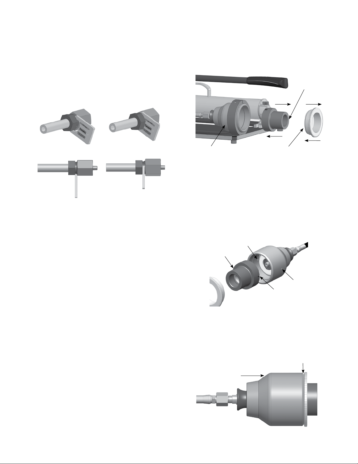
Fig. 2 Indicator Knob in Swaging Position
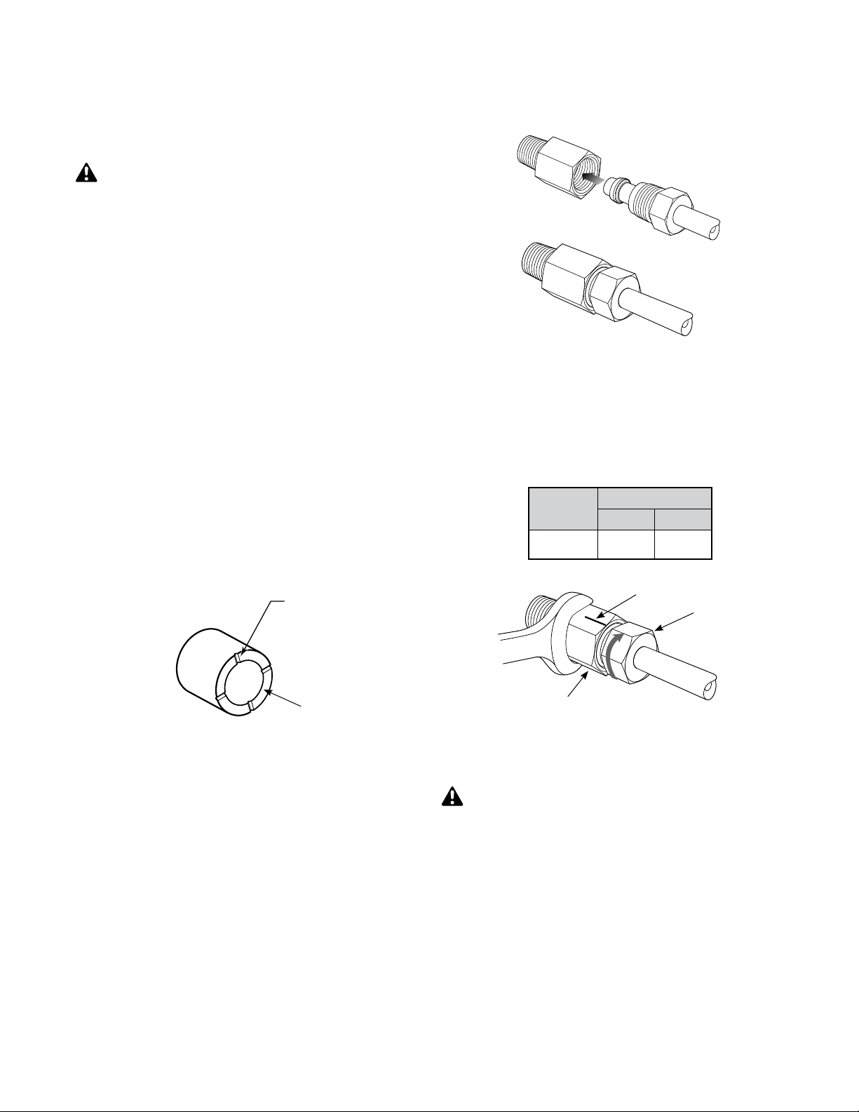
Fig. 1 Nut and Ferrule Orientation
3. Insert the arbored nut and ferrule set into the
Swagelok medium-pressure die. Thread the
nut into the die head to finger-tight. Remove
the arbor, leaving the nut and ferrules in the die
head. The orientation of the nut, rear ferrule,
and front ferrule should be as shown in Fig. 1.
D. If a file is used on the OD, make a 10° x
0.06 in. (1.5 mm) chamfer (as shown below).
C. For the 16FK MHSU, use the chamfer block
provided. Insert the cut end of the tubing
into the chamfer block, and while firmly
holding the tubing, strike the chamfer block
with a hammer to coin the end (as shown
below).
Front ferrule
Back ferrule
Nut Die head
Arbor
Arbor
Operation
1. Open the pump bypass valve by turning the
handle counterclockwise at least one-half to one
turn. It may be necessary to first close the valve
completely by turning the handle clockwise until
it stops. (If the bypass valve is in the full open
position upon receipt of the MHSU unit, it will
not be possible to open it an additional one-half
to one turn.)
2. Prepare tube ends by deburring or using the
Swagelok chamfer block as follows.
Note: Use the chamfer block when preparing up
to and including 1-inch tubing.
A. Cut tubing squarely. Use of a Swagelok tube
saw guide is recommended.
B. Remove any burrs. Use of a Swagelok tube
deburring tool is recommended.
WARNING
Deburr the OD of the tube to ensure
that it properly rests against the piston
shoulder. If the tube is not resting against
the piston shoulder, it could result in
inadequate preswaging, which, in turn,
could lead to premature tube failure and
result in loss of life, injury, or property
damage. One of the causes of the tube
not seating properly could be because it
hasn’t been properly deburred.
4. Insert the tubing into the die head until it rests
firmly against the piston shoulder. Tighten the
nut until finger-tight.
5. Push the indicator knob forward until it snaps
into place. The knob shoulder should be flush
with the hydraulic housing. See Fig. 2.
Knob shoulder is
flush with housing.
Indicator knob
Housing Tubing
Tubing
10°
0.06 in. (1.5 mm)
Strike end with
a hammer to
coin tube end
Tubing
Chamfer block