3
MS-12-37
Revision 2 12-02-CP
Operation
1. Open the pump bypass valve by turning the
handle counterclockwise at least 1/2 to 1 turn.
It may be necessary to first close the valve
completely by turning the handle clockwise until
it stops.
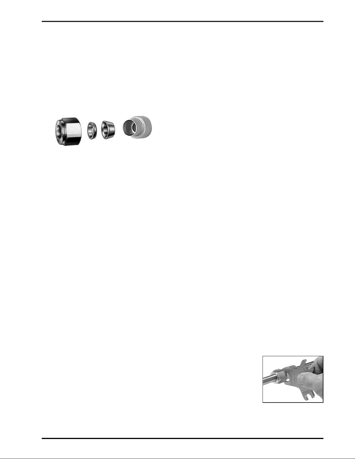
2. Install the Swagelok nut and ferrules onto the
die head in the order and orientation shown
until finger-tight and all die threads are covered
by the nut.
3. Push the indicator knob forward until it snaps
into place. The knob shoulder should be flush
with the hydraulic housing.
Note: If the indicator knob does not snap into
place or is not flush with the housing the piston
may not be fully retracted. This problem may
be caused by the bypass valve being closed or
by the piston binding. Do not proceed until unit
is functioning properly. Contact your
independent Swagelok sales and service
representative for further assistance.
4. Prepare tube ends by deburring or using the
Swagelok chamfer block (as follows and as
shown on the instruction decal in the MHSU
case). The chamfer block procedure should be
followed when using the up to and including
one inch tubing on the MHSU.
A. Cut tubing squarely. Use of a Swagelok
tube saw guide is recommended.
B. For up to and including one inch MHSU,
use the chamfer blocks provided. Insert cut
end of tubing in to the chamfer block and
while firmly holding the tubing, strike the
chamfer block with a hammer to coin the
end (as shown on the instruction decal).
C. If a file is used on the OD, make a 10° x
0.06 in. (1.5 mm) chamfer.
D. Remove any burrs. Use of Swagelok tube
deburring tools is recommended.
NOTE: Deburring is important for proper
fitting function as well as for clean, leak-
free systems. If burrs are not removed from
the OD of the tube, it could prevent the
tube from being fully inserted through the
nut, ferrules or against the shoulder of the
fitting body. ID burrs could also break off
and cause damage in other parts of the
system by lodging in small holes or vents,
or by scratching valve seats or soft seals.
5. Insert tubing into the nut until it rests firmly
against the piston shoulder. Refer to the
Recommended Minimum Wall Thickness of
Tubing for Use with the MHSU table on page
4. Use of tubing below the recommended
minimum wall may result in the tube sticking in
the die head.
6. Close the pump bypass valve to the finger-tight
position by rotating valve handle clockwise until
it stops.
7. While holding the tubing against the piston
shoulder, increase the hydraulic pressure by
using the hand pump until the indicator knob is
released.
Do not keep pumping after the indicator
knob releases. Stop pumping immediately
after the indicator knob pops.
8. Open the pump bypass valve by turning the
handle 1/2 to 1 turn counterclockwise.
9. Unthread the Swagelok nut, and remove the
preswaged assembly from the housing.
10. Inspect the tube end for a radial indentation
bottom marking (see decal in MHSU case).
This indentation indicates the tubing was
properly bottomed in the MHSU. If there is not
a visible indentation, the preswaged assembly
should not be used.
11. Install the preswaged assembly into the fitting
body. Turn the nut onto the fitting body until it is
finger-tight. Hold the fitting body stable and
tighten the nut 1/2 turn with a wrench.
Use the Swagelok MHSU gap inspection
gauge to assure the installer or
inspector that the fitting has been
sufficiently tightened.
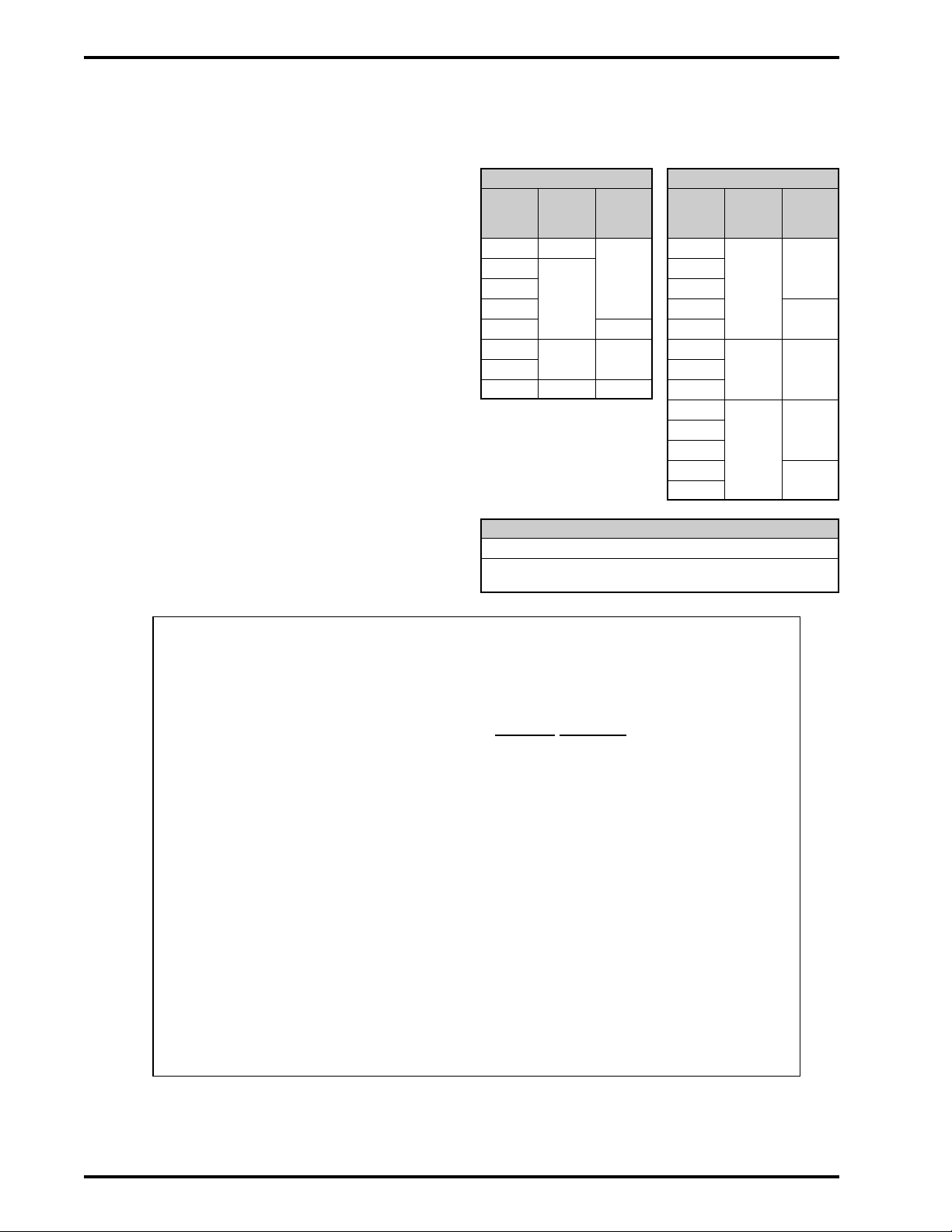
Gauging Instructions
Position the Swagelok MHSU gap inspection gauge
adjacent to the gap between the nut and body hex.
■ If the gauge will not
enter the gap, the
fitting is sufficiently
tightened.
■If the gauge will enter
the gap, additional
tightening is required.
Nut Back
ferrule
Front
ferrule
Die
head