manuals.online logo
Brands
  1. Home
  2. •
  3. Brands
  4. •
  5. Swann
  6. •
  7. Heater
  8. •
  9. Swann Smith's Solano Eco Guide

Swann Smith's Solano Eco Guide

Issue 002 - November 2022 | SmithsEP.co.uk | 1
Installation, commissioning
and user manual
Unit heater
Solano® Eco
Issue 002 | November 2022
ENGLISH | UK | IRL | SmithsEP.co.uk
2 | SmithsEP.co.uk | Issue 002 - November 2022 Issue 002 - November 2022 | SmithsEP.co.uk | 3
1. Overall information
Solano heating and ventilation devices are designed to be applied in the buildings of small and medium capacity, such as: production
and warehouse halls, car showrooms and service stations, sports halls and stadiums, sacral buildings and churches, retail stores
and wholesales outlets, agricultural facilities and exhibition halls. Solano provides a dedicated solution for connection to low water
temperature sources (for example condensing boilers and industrial heat pumps). Main advantages of Solano are: high temperature
of outlet air is generated by low temperature of water supplied to a unit, maximum use of the heating coil surface - new geometry of
coil construction (enhanced ns size, lower space between ns), optimised ow rate of heated outlet air - in effect high air exhaust
temperature generated on each speed of fan.
2. Dimensions
Solano Eco 1, 2, 3 and Mix 1
Solano Eco Max 1, 2, 3 and Mix 2
Elements of the Solano devices
• Casing made of highly resistant EPP (expended polypropylene) material
• Regulated louvres
• 3 step axial fan 350 mm, 450 mm or 550mm dimension; protected from direct access to revolving elements with safety netting
• Heat exchanger – (Cu/AL) made of copper tubes placed in an aluminium lamellar exchanger/block with stub connection ½”, ¾”.
Stub connections are equipped with air-release valves and water agent release
Heater
Eco 1
Heater
Eco 2
Heater
Eco 3
Heater
Eco MAX 1
Heater
Eco MAX 2
Heater
Eco MAX 3
Heater
Eco MIX 1
Heater
Eco MIX 2
Heat output range* kW 10-35 15-50 20-70 25-70 35-95 40-120 - -
Heat output (90/70°C) / ΔT air temperature increase** kW/°C 23kW/18°C 39kW/33°C 50kW/48°C 55kW/30°C 74kW/49°C 94kW/60°C - -
Heat output (70/50°C) / ΔT air temperature increase** kW/°C 16kW/13°C 26kW/22°C 35kW/34°C 40kW/22°C 53kW/35°C 68kW/44°C - -
Heat output (50/30°C) / ΔT air temperature increase** kW/°C 9kW/8°C 13kW/11°C 20kW/20°C 25kW/14°C 32kW/21°C 42kW/27°C - -
Max air output - III speed m3/h 3900 3350 2950 5700 5600 5100 4800 7200
Sound level I/II/III speed**** dB (A) 44/52/62 41/50/60 39/48/60 41/50/59 40/48/58 40/48/58 36/44/54 31/42/49
Number of coil rows - 1 2 3 2 3 3 - -
Max working pressure Mpa 1.6 1.6 - -
Max airow range***** m 24 21 19 26 25 23 13*** 16***
Diameter of connection nozzles inches 3/4” 3/4” - -
Power supply V/Hz A 230/50 1.08A 230/50 2.2A 230/50 1.08A 230/50 2.2A
Motor power W 250 520 250 520
Motor speed rpm 1350 1380 1350 1380
Protection class IP - IP54 IP54 IP54
Weight without water/with water kg 10.8/11.9 12.7/14.8 14.5/16.9 23.6/25.2 25.2/27.4 25.5/28 9.2 15.8
* presented heat output for water agent temperature range 50/30°C – 120-90°C, air inlet temperature 0°C, III speed.
** for air inlet temperature 0°C
*** max height of installation for vertical airow, max working area 380 m² for HEATER MIX 1 and 450 m² for HEATER MIX 2 **** measured in distance of 5m
***** Horizontal range of isothermal steam at velocity of 0,5m/s
Operation and maintenance documentation for the SOLANO RANGE v202103
Solano heating and ventilation devices are designed to be applied in the buildings of small and medium capacity, such as:
production and warehouse halls, car showrooms and service stations, sports halls and stadiums, sacral build-ings and churches,
retail stores and wholesales outlets, agricultural facilities and exhibition halls. Solano provides a dedicated solution for
connection to to low water temperature sources (for example condensing boilers and industrial heat pumps). Main advantages
of HEATER CONDENS are: outlet air is generated by low temperature of water supplied to a unit,
the heating – new geometry of coil construction (enhanced fins size, lower space be-
tween fins), optimised flow rate of heated outlet air – in effect high air exhaust temperature generated on each speed of
fan.
Solano Eco 1, 2, 3 and Mix 1
for the SOLANO RANGE
Solano Eco MAX 1, 2, 3 and Mix 2
Solano
Casing made of highly resistant EPP (expended polypropylene) material
Regulated louvres
3 step axial fan 350 mm, 450 mm or 550mm dimension; protected from direct access to revolving elements with safe-
ty netting
Heat exchanger – (Cu/AL) made of copper tubes placed in an aluminium lamellar exchanger /block with stub connec-
tion ½”, ¾”.Stub connections are equipped with air-release valves and water agent release
MAX 1 MAX 2 MAX 3
kW 10-35 15-50 20-70 25-70 35-95 40-120 - -
℃
) / ΔT air termperature incre kW / ℃ 23 kW/18℃ 39 kW/33℃ 50 kW/48℃ 55 kW/30℃ 74 kW/49℃ 94 kW /60℃ - -
℃
) / ΔT air termperature increase** kW / ℃ 16 kW/13℃ 26 kW/22℃ 35 kW/34℃ 40 kW/22℃ 53 kW/35℃ 68 kW/44℃
℃
) / ΔT air termperature increase** kW / ℃ 9 kW/8℃ 13 kW/11℃ 20 kW/20℃ 25 kW/14℃ 32 kW/21℃ 42 kW/27℃
m3/h 3 900 3 350 2 950 5 700 5 600 5 100 4 800 7 200
dB (A) 44/52/62 41/50/60 39/48/60 41/50/59 40/48/58 40/48/58 36/44/54 31/42/49
coil 1 2 3 2 3 3 - -
MPa 1,6
m 24 21 19 26 25 23 13*** 16***
inch 3/4'' 3/4" - -
V/Hz /A 230/50 1,08A 230/50 2,2A 230/50 1,08A 230/50 2,2A
W 250 520 250 520
RPM 1350 1380 1350 1380
IP 54 IP 54 IP 54
kg 10,8/11,9 12,7/14,8 14,5/16,9 23,6/25,2 25,2/27,4 25,5/28 9,2 15,8
90°C, air inlet temperature 0°C, III speed.
for air inlet temperature 0°C
flow, max working area 380 m² for HEATER MIX 1 and 450 m² for HEATER MIX 2
1,6
Contents
Introduction 2
Product dimensions 2/3
General information 4
Assembly 4
Electrical installation 6
Water installation 6
Automatic Control - installation 7
Operation 7
Maintenance 7
Technical data 8
Electrical connection diagrams 14
Panel Intelligent - programmable controller manual 16
Registering your product 18
Disposal 18
After sales and spares 18
4 | SmithsEP.co.uk | Issue 002 - November 2022 Issue 002 - November 2022 | SmithsEP.co.uk | 5
SOLANO RANGE


To sustain proper functioning of the device keep a safe distance– 200 mm from its sides and 300 mm from its backside
(from the fan)


While drilling the holes in marked places be careful not to damage the coil by going deeper than 20mm!
The bracket set consist of: a holder, two sleeves, two
M8 screws and washers. In order to mount the brack-
et, drill two Ø12-13mm holes in places visibly marked
on the casing. Insert sleeves into drilled holes and
place the bracket in. The included holder must be
screwed with M8 screws with washers.
To mount the heater to the ceiling, use M8 mounting
pins. Drill two Ø8-9mm holes in places visibly marked
on the casing. Mounting pins may be screwed into the
frame not deeper than 20 mm
To mount HEATER MIX air mixer to the ceiling, use M8
mounting pins. Drill two Ø8-9mm holes in places visi-
bly marked on the casing. Mounting pins may be
screwed into the frame of a heat exchanger to the
maximum depth of 20 mm. Mounting pins and con-
necting elements are not included with the unit
3. General information
Solano heating and ventilation devices are manufactured in compliance with standards concerning quality, ecology, utility and work
comfort. Solano devices are delivered ready-to-use in a cardboard package that is to protect from mechanical damages damage during
transit. The package consists of: the device, wall mounting bracket, the Manual (Operation and Maintenance Documentation) and
Guarantee. If the optional automatic control ordered, it shall be delivered in a separate package. Make sure all the aforementioned
elements are in the package immediately after the delivery. In the absence of any element, please advise Smith’s immediately.
ATTENTION!
• Before mounting read the manual carefully and adhere to the rules concerning the mounting procedures. Failure to do so, may
result in inappropriate functioning of the device and the loss of the guarantee rights.
• Pay special attention when working with electrical elements of the device.
• Any installation operations must be carried out by qualied persons with appropriate authorisations
4. Assembly
Prior to any installation procedures, take the following aspects into consideration: easy access for maintenance works, access to water
and electrical installation, appropriate air distribution in a room.
Each Solano unit is equipped with a set of 2 interchangeable colour inserts; in order to change the colour, remove the insert from the
front panel and place the desired one back in place.
It is advisable to mount the device to the wall or the ceiling on original mounting brackets, supporting mount pins (not delivered
with the device) or supporting constructions (shapes and dimensions of the supporting construction may be individually designed in
compliance with durability and strength requirements).
In case of mounting to the ceiling, pay attention to the fact that air-release/venting of the device may be difcult so it is advisable to
place vent at the highest point of the pipework.
The device may be mounted to the wall with the use of a mounting bracket at the angle of 0°, 30° or 60 °. A mounting bracket holder
is made of curved prole. It has two holes for vertical assembly. Assembly to the wall and/or to the ceiling is possible at different angles
but it requires making necessary holes in the holder.

Before mounting read the manual carefully and adhere to the rules concerning the mounting procedures. Failure to
do so, may result in inappropriate functioning of the device and the loss of the guarantee rights.

Pay special attention when working with electrical elements of the device.
Any installation operations must be carried out by qualified persons with appropriate authorizations
for the SOLANO RANGE
Solano heating and ventilation devices are manufactured in compliance with standards concerning quality, ecology, utility and
work comfort. Solano devices are delivered ready-to-use in a cardboard package that is to protect from mechanical damages
damage during transit. The package consists of: the device, wall mounting bracket, the Manual (Operation and Maintenance
Documentation) and Guarantee. If the optional automatic control ordered, it shall be delivered in a separate package. Make
sure all the aforementioned elements are in the package immediately after the delivery. In the absence of any element,
please advise Smith's immediately.
Prior to any installation procedures, take the following aspects into consideration: easy access for maintenance works, access to
water and electrical installation, appropriate air distribution in a room.
Each Solano unit is equipped with a set of 2 interchangeable colour inserts; in order to change the color, remove the insert
from the front panel and place the desired one back in place.
It is advisable to mount the device to the wall or the ceiling on original mounting brackets, supporting mount pins (not delivered
with the device) or supporting constructions (shapes and dimensions of the supporting construction may be individually de-
signed in compliance with durability and strength requirements).
In case of mounting to the ceiling, pay attention to the fact that air-release/venting of the device may be difficult so it is advis-
able to place vent at the highest point of the pipework.
The device may be mounted to the wall with the use of a mounting bracket at the angle of 0°, 30° or 60 °. A mounting bracket
holder is made of curved profile. It has two holes for vertical assembly. Assembly to the wall and/or to the ceiling is possible at
different angles but it requires making necessary holes in the holder.
A = 90mm Solano Eco 1, 2, 3 & Mix 1
A = 120mm Solano Eco MAX 1, 2, 3 & Mix 2
Mounting bracket to the Solano
The bracket set consist of: a holder, two sleeves, two M8 screws
and washers.
In order to mount the bracket, drill two Ø12-13mm holes in places
visibly marked on the casing.
Insert sleeves into drilled holes and place the bracket in. The
included holder must be screwed with M8 screws with washers.
SOLANO RANGE


To sustain proper functioning of the device keep a safe distance– 200 mm from its sides and 300 mm from its backside
(from the fan)


While drilling the holes in marked places be careful not to damage the coil by going deeper than 20mm!
The bracket set consist of: a holder, two sleeves, two
M8 screws and washers. In order to mount the brack-
et, drill two Ø12-13mm holes in places visibly marked
on the casing. Insert sleeves into drilled holes and
place the bracket in. The included holder must be
screwed with M8 screws with washers.
To mount the heater to the ceiling, use M8 mounting
pins. Drill two Ø8-9mm holes in places visibly marked
on the casing. Mounting pins may be screwed into the
frame not deeper than 20 mm
To mount HEATER MIX air mixer to the ceiling, use M8
mounting pins. Drill two Ø8-9mm holes in places visi-
bly marked on the casing. Mounting pins may be
screwed into the frame of a heat exchanger to the
maximum depth of 20 mm. Mounting pins and con-
necting elements are not included with the unit
Installation of mounting pins
To mount the heater to the ceiling, use M8 mounting pins.
Drill two Ø8-9mm holes in places visibly marked on the casing.
Mounting pins may be screwed into the frame not deeper than
20mm.
ATTENTION!
• While drilling the holes in marked places be careful not to
damage the coil by going deeper than 20mm!
SOLANO RANGE


To sustain proper functioning of the device keep a safe distance– 200 mm from its sides and 300 mm from its backside
(from the fan)


While drilling the holes in marked places be careful not to damage the coil by going deeper than 20mm!
The bracket set consist of: a holder, two sleeves, two
M8 screws and washers. In order to mount the brack-
et, drill two Ø12-13mm holes in places visibly marked
on the casing. Insert sleeves into drilled holes and
place the bracket in. The included holder must be
screwed with M8 screws with washers.
To mount the heater to the ceiling, use M8 mounting
pins. Drill two Ø8-9mm holes in places visibly marked
on the casing. Mounting pins may be screwed into the
frame not deeper than 20 mm
To mount HEATER MIX air mixer to the ceiling, use M8
mounting pins. Drill two Ø8-9mm holes in places visi-
bly marked on the casing. Mounting pins may be
screwed into the frame of a heat exchanger to the
maximum depth of 20 mm. Mounting pins and con-
necting elements are not included with the unit
X = 420mm Eco 1, 2, 3 & Mix 1
X = 516mm Eco MAX 1, 2, 3 & Mix 2
Assembly of Solano MIX air mixer
To mount Solano MIX air mixer to the ceiling, use M8
mounting pins.
Drill two Ø8-9mm holes in places visibly marked on the casing.
Mounting pins may be screwed into the frame of a heat
exchanger to the maximum depth of 20mm. Mounting pins and
connecting elements are not included with the unit.
NOTICE!
• To sustain proper functioning of the device keep a safe distance - 200 mm from its sides and 300 mm from
its backside to the fan
6 | SmithsEP.co.uk | Issue 002 - November 2022 Issue 002 - November 2022 | SmithsEP.co.uk | 7
5. Electrical installation
The electrical installation and connection to power supply must be done in compliance with the existing regulations and standards for
building industry.
The fan’s engine is equipped with the internal temperature limit fuse protecting the engine from its overheating.
The unit set does not consist of: a feeding cable, a master switch (see diagram)
The electrical installation must be done by an authorised person, acquainted with the Manual. The connection of the feeding cable and
master switch must be done in compliance with electrical diagram (with or without the automatic control, depending on the option
chosen). Any and all damages incurred as a result of the aforementioned causes are not provided with the Guarantee and the user will
be charged with any costs of the device exchange. The connection of the automatic control should be carried out in accordance with
the electrical diagram.
In case of any doubts or problems, unplug the device and contact the device’s installer or Smith’s Authorised Service.
6. Water installation
The installation of the unit should be done in a way enabling maintenance service; on both stub pipes manual closing valves should
be installed in order to cut off the device. Feeding cables of the heater shall be connected in accordance with the symbols/marking on
the casing (inlet/outlet). In case of electromagnetic valve (with the option of the automatic control) it should be installed on the outlet
as it may be damaged otherwise. When the pipework is being connected to the exchanger, secure the connections of the heater from
oscillating torque (see gure) that may cause leakage in the exchanger.
Heating medium
The connector pipes are at the back of the device.
When connecting the hydraulic pipes/connections, make sure you
secure the connector pipes against rotational torque.
Notice that the connector pipes are not strained by the pipes.
The valve of heating medium is on the supply pipe and the vent is
on the return pipe.
Use exible connections to allow the heater to be turned to the
sides. Depending on the exible connections, the maximum turn
is 70° - for Solano Eco MAX, 78° - for Solano Eco 1, 2 and 3 to
both sides. Figure shows maximum angle to one side and 50° to
the other with minimal distance left for connections.
SOLANO RANGE
The electrical installation and connection to power supply must be done in compliance with the existing regulations and stand-
ards for building industry.
The fan’s engine is equipped with the internal temperature limit fuse protecting the engine from its overheating.
The unit set does not consist of: a feeding cable, a master switch (see diagram)
The electrical installation must be done by an authorized person, acquainted with the Manual. The connection of the feeding
cable and master switch must be done in compliance with electrical diagram (with or without the automatic control, depending
on the option chosen). Any and all damages incurred as a result of the aforementioned causes are not provided with the Guar-
antee and the user will be charged with any costs of the device exchange. The connection of the automatic control should be
carried out in accordance with the electrical diagram.
In case of any doubts or problems, unplug the device and contact the device’s installer or SONNIGER Authorized Service.
The installation of the unit should be done in a way enabling maintenance service; on both stub pipes manual closing valves
should be installed in order to cut off the device. Feeding cables of the heater shall be connected in accordance with the sym-
bols/marking on the casing (inlet/outlet). In case of electromagnetic valve (with the option of the automatic control) it should
be installed on the outlet as it may be damaged otherwise. When the pipework is being connected to the exchanger, secure the
connections of the heater from oscillating torque (see figure) that may cause leakage in the exchanger.
The connector pipes are at the back of the
device. When connecting the hydraulic
pipes/connections, make sure you secure the
connector pipes against rotational torque.
Notice that the connector pipes are not
strained by the pipes. The valve of heating
medium is on the supply pipe and the vent is
on the return pipe.
Use flexible connections to allow the heater to
be turned to the sides. Depending on the
flexible connections, the maximum turn
is 70° - for HEATER CONDENS MAX,
78° - for HEATER CONDENS CR1, CR2, CR3,
68° - for HEATER CONDENS ONE , to both
sides. Figure shows maximum angle to one
side and 50° to the other with minimal dis-
tance left for connections.
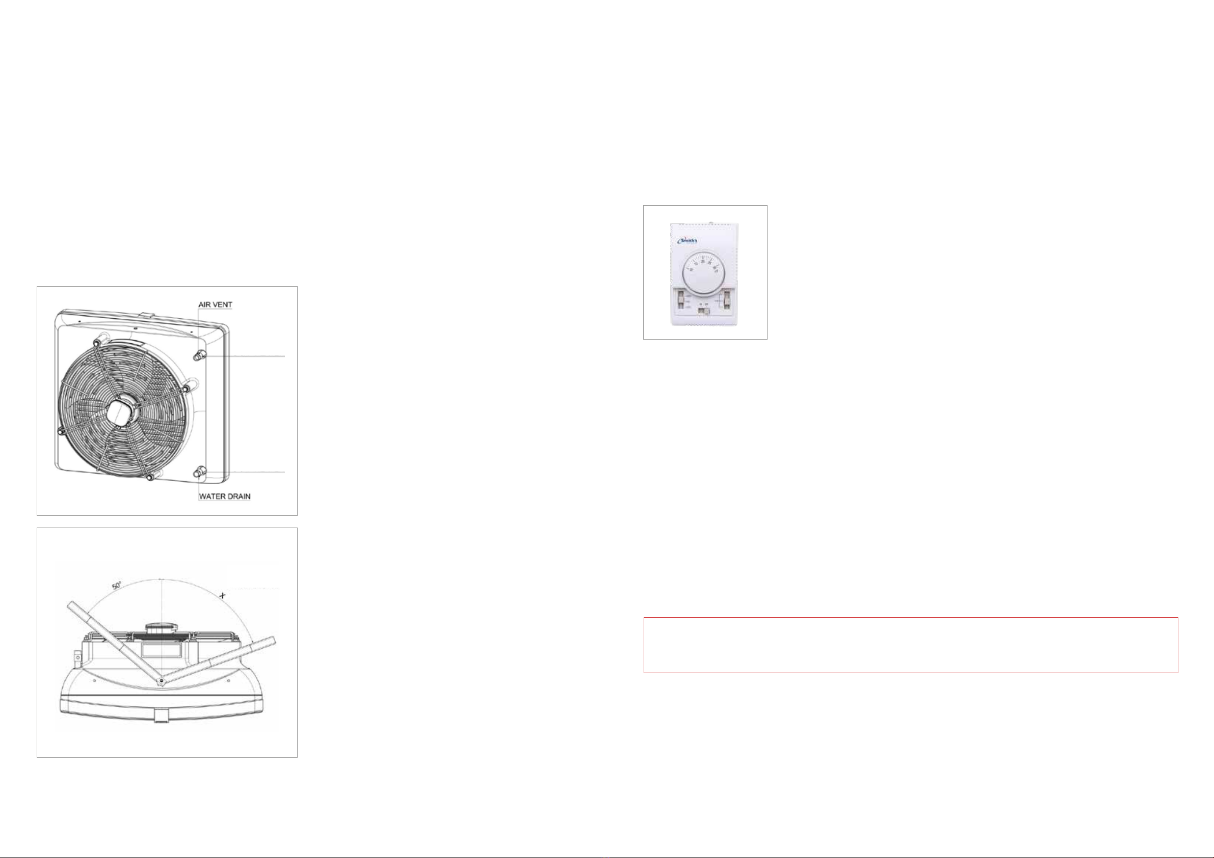
7. Automatic control - installation
A set of automatic control may be used (powered 230V) that consists of the following:
• COMFORT panel - including room thermostat and switch for regulation of 3 speeds of fan. One COMFORT panel may regulate up to
3 pcs of Solano Eco 1, 2 and 3 units or 2 pcs of Solano Eco MAX
• 2-way water valve with actuator; valve should be installed on a return stub of the heater
• INTELLIGENT electronic control panel with an automatic speed controller, weekly program and BMS communication.
One INTELLIGENT panel may regulate up to 2 pcs of Solano Eco units or for single Solano Eco MAX
• Splitter MULTI 6 - control up to 6 pcs of Solano Eco, Solano Eco MAX units from one COMFORT or INTELLIGENT Panel
The system is ready to start once the connections between the thermostat and the valve actuator are done, 230V power is supplied to
the thermostat and the fan’s motor is powered by the revs controller.
COMFORT panel description
ON/OFF - turning ON/OFF a unit
I-II-III - switch for fan speed regulation
HEAT - thermostat sends signal for valve and actuator and fan, fan turns off when temperature in
room is achieved, valve/actuator closes water supply.
FAN - function not active, unit will not operate when FAN switch is selected
COOL - thermostat sends signal only to fan and to the servo of the valve, fan begins operation
starting from temperature which is set on thermostat (function used to air mixer Solano MIX or for
room ventilation in summer season)
8. First start
Do all the connections (electrical, water and automatic control), check for tightness of all connections done by an installer and
air-release/vent the device then start the device in the following sequence:
1. Switch on the mains,
2. Set requested speed of fan on revs controller,
3. Set requested temperature on thermostat,
The fan operates continuously irrespective of whether the heater’s valve is opened or not.
9. Turning off
To switch the device off do the following:
1. Set minimum temperature on thermostat - after 7 seconds valve will be closed and heating switched off.
2. Set main switch to the “0” position (off); fan will be switched off and the thermostat will be off the power.
10. Operation
The engine and fan used in Solano Eco and Eco MAX units are maintenance-free devices but regular check-ups are advised, especially
motor and bearing (fan’s rotor should rotate freely, free from any axial and radial throws and undesired knocks/rattles).
NOTICE!
• In case of any metallic knocks, vibration or increase in sound level check if the fan mounting/xing does not work loose contact
the installer or Smith’s Authorised Service
11. Maintenance
The heat exchanger requires systematical cleaning all with all dirt/impurities cleaned off. Before the start of the heating period the heat
ex-changer is advised to be cleaned with compressed air directed to the air outlets; there is no need for dismantling of the device. Pay
special attention when cleaning the exchanger’s n due to high possibility of damaging them. If ns are bent use a tool specically
designated to carry out such repairs. If the device has not been used for a longer period of time, unplug it before the next use.
The heat exchanger is not equipped with any frost protection device. The heat exchanger may be damaged if the room temperature
goes below 0°C.
Anti-freeze liquid must be added to the water circulation/system. Anti-freeze liquid must be appropriate for the material the exchanger
is made of (copper) as well as other elements of the hydraulic system. The liquid must be diluted with water according to the solution
recommended by the anti-freeze manufacturer.
OUT
G 3/4” Eco 1, 2 & 3
G 3/4” Eco MAX 1,
2 & 3
IN
G 3/4” Eco 1, 2 & 3
G 3/4” Eco MAX 1,
2 & 3
X = 78° Eco 1, 2 & 3
X = 70° Eco MAX
1, 2 & 3
8 | SmithsEP.co.uk | Issue 002 - November 2022 Issue 002 - November 2022 | SmithsEP.co.uk | 9
inlet/outlet water temperature water 50/30 °C water 60/40 °C water 70/50 °C
inlet air temperature °C 0 5 10 15 20 0 5 10 15 20 0 5 10 15 20
High speed - Air flow 3350 m³/h (speed 3)
heat output kW 12.5 10.5 8.4 6.1 2.8 19.6 17.3 15.0 12.6 10.2 26.2 23.7 21.3 18.8 16.3
outlet air temperature °C 10.7 14.3 16.9 19.5 21.9 16.6 19.0 21.2 23.5 25.8 22.1 24.6 27.1 29.5 32.0
water ow m³/h 0.7 0.6 0.5 0.3 0.2 1.0 0.8 0.7 0.6 0.5 1.2 1.1 1.0 0.9 0.8
pressure drop kPa 4.4 3.2 2.1 1.2 0.3 7.2 5.8 4.4 3.3 2.2 10.5 8.8 7.2 5.8 4.5
Mid speed - Air flow 2000 m³/h (speed 2)
heat output kW 9.1 7.6 6.0 4.2 2.4 14.2 12.6 10.9 9.2 7.4 19.0 17.2 15.5 13.7 11.9
outlet air temperature °C 12.9 19.4 21.4 23.0 24.5 20.2 22.1 23.9 25.8 27.7 26.9 28.9 30.9 33.0 35.0
water ow m³/h 0.5 0.4 0.3 0.2 0.1 0.7 0.6 0.5 0.4 0.4 0.9 0.8 0.7 0.6 0.5
pressure drop kPa 2.5 1.8 1.2 0.6 0.2 4.1 3.3 2.5 1.9 1.3 5.9 4.9 4.1 3.3 2.6
Low speed - Air flow 1450 m³/h (speed 1)
heat output kW 7.3 6.1 4.8 2.9 2.1 11.5 10.2 8.8 7.4 6.0 15.3 13.9 12.5 11.1 9.6
outlet air temperature °C 14.4 21.0 22.5 22.6 25.5 22.5 24.1 25.8 27.3 28.8 29.9 31.7 33.5 35.2 37.0
water ow m³/h 0.4 0.3 0.3 0.2 0.1 0.6 0.5 0.4 0.4 0.3 0.7 0.6 0.6 0.5 0.4
pressure drop kPa 1.7 1.2 0.8 0.3 0.2 2.8 2.2 1.7 1.3 0.9 4.0 3.4 2.8 2.2 1.8
inlet/outlet water temperature water 80/60 °C water 90/70 °C water 120/90 °C
inlet air temperature °C 0 5 10 15 20 0 5 10 15 20 0 5 10 15 20
High speed - Air flow 3350 m³/h (speed 3)
heat output kW 32.5 30.0 27.5 24.9 22.4 39.3 36.7 34.0 31.4 28.8 53.4 50.7 48.0 45.3 42.6
outlet air temperature °C 27.2 29.7 32.2 34.8 37.3 32.4 35.0 37.6 40.2 42.7 45.0 47.6 50.4 53.1 55.9
water ow m³/h 1.5 1.3 1.2 1.1 1.0 1.7 1.6 1.5 1.4 1.2 1.5 1.4 1.3 1.3 1.2
pressure drop kPa 14.1 12.2 10.4 8.8 7.2 18.2 16.0 14.0 12.1 10.4 13.6 12.4 11.2 10.1 9.0
Mid speed - Air flow 2000 m³/h (speed 2)
heat output kW 23.5 21.7 19.9 18.1 16.3 28.4 26.5 24.6 22.7 20.9 38.6 36.7 34.8 32.8 30.9
outlet air temperature °C 32.9 35.0 37.1 39.2 41.3 39.2 41.4 43.5 45.6 47.8 54.5 56.7 59.0 61.2 63.4
water ow m³/h 1.1 1.0 0.9 0.8 0.7 1.2 1.1 1.1 1.0 0.9 1.1 1.0 1.0 0.9 0.9
pressure drop kPa 7.9 6.8 5.8 4.9 4.1 10.1 8.9 7.8 6.8 5.8 7.6 6.9 6.3 5.7 5.1
Low speed - Air flow 1450 m³/h (speed 1)
heat output kW 19.0 17.5 16.1 14.6 13.2 22.9 21.4 19.9 18.4 16.9 31.2 29.6 28.1 26.5 25.0
outlet air temperature °C 36.6 38.4 40.2 42.1 43.9 43.5 45.4 47.3 49.2 51.1 60.6 62.5 64.6 66.5 68.4
water ow m³/h 0.8 0.8 0.7 0.7 0.6 1.0 0.9 0.9 0.8 0.7 0.9 0.8 0.8 0.7 0.7
pressure drop kPa 5.4 4.7 4.0 3.4 2.8 6.9 6.1 5.3 4.6 4.0 5.2 4.7 4.3 3.9 3.5
Heater Eco 2
12. Technical data
inlet/outlet water temperature water 80/60 °C water 90/70 °C water 120/90 °C
inlet air temperature °C 0 5 10 15 20 0 5 10 15 20 0 5 10 15 20
High speed - Air flow 3900 m³/h (speed 3)
heat output kW 21.1 19.4 17.6 15.9 14.2 23.0 21.4 19.7 17.9 16.1 37.9 35.9 33.9 31.9 29.9
outlet air temperature °C 17.2 21.7 26.3 30.8 35.5 18.0 25.8 30.7 35.5 40.3 30.7 36.0 41.3 46.6 51.9
water ow m³/h 0.8 0.8 0.7 0.6 0.6 0.8 0.8 0.7 0.7 0.6 0.9 0.8 0.8 0.7 0.7
pressure drop kPa 9.7 8.4 7.1 5.9 4.8 9.7 8.7 7.7 6.8 5.9 9.4 8.5 7.7 6.9 6.1
Mid speed - Air flow 2500 m³/h (speed 2)
heat output kW 16.4 15.1 13.8 12.4 11.1 21.0 19.5 18.1 16.6 15.2 29.6 28.0 26.5 24.9 23.4
outlet air temperature °C 20.9 25.2 29.4 33.7 38.0 25.6 30.1 34.6 39.0 43.6 37.4 42.3 47.3 52.2 57.3
water ow m³/h 0.7 0.6 0.5 0.5 0.4 0.8 0.7 0.7 0.6 0.6 0.7 0.6 0.6 0.6 0.5
pressure drop kPa 6.3 5.4 4.6 3.8 3.1 8.0 7.1 6.2 5.3 4.5 6.0 5.5 4.9 4.4 4.0
Low speed - Air flow 1850 m³/h (speed 1)
heat output kW 13.8 12.7 11.6 10.4 9.3 17.6 16.4 15.2 14.0 12.8 24.8 23.5 22.2 20.9 19.6
outlet air temperature °C 23.6 27.7 31.8 35.8 39.8 29.0 33.2 37.5 41.8 45.9 42.3 47.0 51.8 56.4 61.2
water ow m³/h 0.5 0.5 0.5 0.4 0.4 0.6 0.6 0.6 0.5 0.5 0.6 0.5 0.5 0.5 0.4
pressure drop kPa 4.6 3.9 3.3 2.8 2.3 5.9 5.2 4.5 3.9 3.3 4.4 4.0 3.6 3.2 2.9
inlet/outlet water temperature water 50/30 °C water 60/40 °C water 70/50 °C
inlet air temperature °C 0 5 10 15 20 0 5 10 15 20 0 5 10 15 20
High speed - Air flow 3900 m³/h (speed 3)
heat output kW 8.7 7.1 5.4 3.6 1.7 12.4 10.8 9.3 7.7 6.1 16.0 14.4 12.9 11.3 9.7
outlet air temperature °C 7.3 10.5 14.2 17.8 21.3 10.2 14.4 18.5 22.7 26.9 12.8 16.9 21.2 25.3 29.4
water ow m³/h 0.4 0.3 0.2 0.2 0.1 0.5 0.5 0.4 0.3 0.3 0.7 0.6 0.6 0.5 0.4
pressure drop kPa 2.8 1.9 1.2 0.6 0.2 4.8 3.8 2.9 2.1 1.4 7.1 5.9 4.8 3.8 2.9
Mid speed - Air flow 2500 m³/h (speed 2)
heat output kW 6.7 5.5 4.2 2.1 1.5 9.7 8.5 7.2 6.0 4.7 12.5 11.3 10.0 8.8 7.6
outlet air temperature °C 8.8 11.6 15.0 17.6 21.8 12.4 16.3 20.2 24.1 28.0 15.6 19.5 23.3 27.2 31.1
water ow m³/h 0.3 0.2 0.2 0.1 0.1 0.4 0.4 0.3 0.3 0.2 0.5 0.5 0.4 0.4 0.3
pressure drop kPa 1.8 1.2 0.8 0.2 0.1 3.1 2.4 1.9 1.3 0.9 4.6 3.8 3.1 2.5 1.9
Low speed - Air flow 1850 m³/h (speed 1)
heat output kW 5.6 4.5 3.4 2.0 1.4 8.1 7.1 6.1 5.0 3.9 10.5 9.5 8.4 7.4 6.4
outlet air temperature °C 9.9 12.4 15.5 18.2 22.3 14.0 17.8 21.5 25.1 28.6 17.7 21.4 25.1 28.7 32.3
water ow m³/h 0.3 0.2 0.2 0.1 0.1 0.4 0.3 0.3 0.2 0.2 0.5 0.4 0.4 0.3 0.3
pressure drop kPa 1.3 0.9 0.5 0.2 0.1 2.3 1.8 1.4 1.0 0.6 3.4 2.8 2.3 1.8 1.4
Heater Eco 1
10 | SmithsEP.co.uk | Issue 002 - November 2022 Issue 002 - November 2022 | SmithsEP.co.uk | 11
12. Technical data
inlet/outlet water temperature water 50/30 °C water 60/40 °C water 70/50 °C
inlet air temperature °C 0 5 10 15 20 0 5 10 15 20 0 5 10 15 20
High speed - Air flow 2950 m³/h (speed 3)
heat output kW 20.0 17.0 14.0 10.8 7.2 27.9 24.8 21.7 18.6 15.3 35.3 32.1 29.0 25.8 22.6
outlet air temperature °C 20.1 21.5 22.8 24.0 24.9 27.2 28.8 30.2 31.6 33.0 34.2 35.8 37.3 38.7 40.2
water ow m³/h 1.0 0.9 0.7 0.5 0.4 1.3 1.2 1.0 0.9 0.7 1.7 1.5 1.4 1.2 1.1
pressure drop kPa 7.9 5.9 4.1 2.6 1.3 12.5 10.1 8.0 6.0 4.3 17.8 15.0 12.5 10.1 8.0
Mid speed - Air flow 1700 m³/h (speed 2)
heat output kW 13.5 11.5 9.4 7.2 3.9 18.7 16.7 14.6 12.6 10.4 23.6 21.5 19.5 17.4 15.3
outlet air temperature °C 23.9 24.8 25.5 26.3 27.0 32.3 33.2 34.2 35.1 35.9 40.4 41.4 42.4 43.4 44.4
water ow m³/h 0.7 0.6 0.5 0.4 0.2 0.9 0.8 0.7 0.6 0.5 1.1 1.0 0.9 0.8 0.7
pressure drop kPa 3.9 2.9 2.0 1.3 0.4 6.1 5.0 3.9 3.0 2.1 8.6 7.3 6.1 5.0 3.9
Low speed - Air flow 1200 m³/h (speed 1)
heat output kW 10.4 8.8 7.2 5.4 3.4 14.4 12.9 11.3 9.7 8.0 18.1 16.6 15.0 13.4 11.8
outlet air temperature °C 26.1 27.9 29.6 31.1 32.3 35.2 36.0 36.6 37.1 37.6 44.0 44.7 45.5 46.2 46.9
water ow m³/h 0.5 0.4 0.4 0.3 0.2 0.7 0.6 0.5 0.5 0.4 0.9 0.8 0.7 0.6 0.6
pressure drop kPa 2.4 1.8 1.3 0.8 0.3 3.8 3.1 2.5 1.9 1.3 5.4 4.6 3.8 3.1 2.5
inlet/outlet water temperature water 80/60 °C water 90/70 °C water 120/90 °C
inlet air temperature °C 0 5 10 15 20 0 5 10 15 20 0 5 10 15 20
High speed - Air flow 2950 m³/h (speed 3)
heat output kW 42.5 39.4 36.2 33.0 29.8 50.1 46.9 43.6 40.4 37.2 67.1 63.8 60.5 57.2 54.0
outlet air temperature °C 41.0 42.6 44.1 45.7 47.2 47.9 49.5 51.0 52.6 54.1 63.5 65.0 66.5 68.0 69.5
water ow m³/h 2.0 1.8 1.7 1.5 1.4 2.3 2.1 2.0 1.9 1.7 2.0 1.9 1.8 1.7 1.6
pressure drop kPa 23.6 20.5 17.6 14.9 12.4 29.9 26.5 23.3 20.3 17.5 22.5 20.6 18.7 16.9 15.2
Mid speed - Air flow 1700 m³/h (speed 2)
heat output kW 28.3 26.3 24.2 22.1 20.0 33.3 31.2 29.1 27.0 24.9 44.7 42.5 40.4 38.2 36.1
outlet air temperature °C 48.3 49.3 50.4 51.4 52.4 56.2 57.3 58.4 59.4 60.5 74.6 75.6 76.7 77.7 78.7
water ow m³/h 1.3 1.2 1.1 1.0 0.9 1.5 1.4 1.3 1.2 1.1 1.4 1.3 1.2 1.2 1.1
pressure drop kPa 11.3 9.9 8.5 7.2 6.1 14.3 12.7 11.2 9.8 8.5 10.8 9.9 9.0 8.2 7.4
Low speed - Air flow 1200 m³/h (speed 1)
heat output kW 21.7 20.2 18.6 17.0 15.4 25.5 23.9 22.3 20.7 19.1 34.2 32.6 31.0 29.4 27.8
outlet air temperature °C 54.2 53.3 54.0 54.8 55.5 60.4 61.1 61.9 62.7 63.4 79.6 80.4 81.2 81.9 82.7
water ow m³/h 1.0 0.9 0.9 0.8 0.7 1.2 1.1 1.0 0.9 0.9 1.0 1.0 0.9 0.9 0.8
pressure drop kPa 7.0 6.1 5.3 4.5 3.8 8.8 7.9 6.9 6.1 5.3 6.7 6.1 5.6 5.1 4.6
Heater Eco 3
inlet/outlet water temperature water 50/30 °C water 60/40 °C water 70/50 °C
inlet air temperature °C 0 5 10 15 20 0 5 10 15 20 0 5 10 15 20
High speed - Air flow 5700 m³/h (speed 3)
heat output kW 24.5 20.5 16.5 12.3 7.5 32.2 28.3 24.5 20.6 16.7 39.7 35.9 32.0 28.3 24.5
outlet air temperature °C 13.7 16.8 19.8 22.7 25.0 18.0 21.1 24.2 27.3 30.2 22.3 25.5 28.6 31.7 34.8
water ow m³/h 0.8 0.6 0.5 0.4 0.2 1.0 0.9 0.8 0.7 0.5 1.3 1.2 1.0 0.9 0.8
pressure drop kPa 3.5 2.5 1.7 0.9 0.3 5.8 4.6 3.5 2.6 1.8 8.4 7.0 5.7 4.5 3.5
Mid speed - Air flow 3900 m³/h (speed 2)
heat output kW 19.6 16.4 13.1 9.7 4.4 25.7 22.6 19.5 16.5 13.4 31.7 28.6 25.6 22.6 19.6
outlet air temperature °C 15.9 18.6 21.3 23.7 24.4 20.9 23.7 26.6 29.2 31.8 25.9 28.8 31.6 34.5 37.2
water ow m³/h 0.9 0.8 0.6 0.5 0.2 1.3 1.1 1.0 0.8 0.7 1.6 1.4 1.3 1.1 1.0
pressure drop kPa 5.1 3.7 2.5 1.4 0.4 8.5 6.7 5.2 3.8 2.6 12.3 10.2 8.3 6.7 5.1
Low speed - Air flow 2800 m³/h (speed 1)
heat output kW 15.9 13.3 10.6 7.7 4.0 20.9 18.4 15.9 13.4 10.8 25.6 23.2 20.7 18.3 15.9
outlet air temperature °C 18.0 20.4 22.7 24.5 25.4 23.6 26.2 28.7 31.0 33.3 29.2 31.9 34.5 37.0 39.4
water ow m³/h 0.8 0.6 0.5 0.4 0.2 1.0 0.9 0.8 0.7 0.5 1.3 1.2 1.0 0.9 0.8
pressure drop kPa 3.5 2.5 1.7 0.9 0.3 5.8 4.6 3.5 2.6 1.8 8.4 7.0 5.7 4.5 3.5
inlet/outlet water temperature water 80/60 °C water 90/70 °C water 120/90 °C
inlet air temperature °C 0 5 10 15 20 0 5 10 15 20 0 5 10 15 20
High speed - Air flow 5700 m³/h (speed 3)
heat output kW 47.5 43.6 39.8 36.0 32.2 55.0 51.1 47.2 43.4 39.6 72.4 68.5 64.5 60.6 56.8
outlet air temperature °C 26.0 29.2 32.3 35.4 38.4 30.1 33.3 36.4 39.5 42.6 39.3 42.6 45.9 49.1 52.2
water ow m³/h 1.5 1.4 1.3 1.2 1.0 1.8 1.7 1.5 1.4 1.3 1.6 1.5 1.4 1.3 1.3
pressure drop kPa 11.3 9.7 8.2 6.8 5.6 14.5 12.7 11.0 9.4 8.0 10.9 9.8 8.8 7.9 7.0
Mid speed - Air flow 3900 m³/h (speed 2)
heat output kW 37.8 34.7 31.7 28.7 25.7 43.7 40.6 37.6 34.5 31.5 57.4 54.3 51.1 48.0 45.0
outlet air temperature °C 30.2 33.1 36.0 38.7 41.5 34.9 37.8 40.7 43.5 46.3 45.8 48.8 51.9 54.8 57.7
water ow m³/h 1.9 1.8 1.6 1.4 1.3 2.2 2.1 1.9 1.8 1.6 2.0 1.9 1.8 1.7 1.5
pressure drop kPa 16.6 14.2 12.0 10.0 8.2 21.4 18.7 16.2 13.9 11.8 16.1 14.5 13.0 11.6 10.3
Low speed - Air flow 2800 m³/h (speed 1)
heat output kW 30.6 28.1 25.6 23.2 20.8 35.3 32.8 30.4 27.9 25.5 46.5 43.9 41.3 38.9 36.4
outlet air temperature °C 34.0 36.8 39.3 41.8 44.2 39.3 42.0 44.6 47.1 49.7 51.5 54.5 57.2 59.9 62.5
water ow m³/h 1.5 1.4 1.3 1.2 1.0 1.8 1.7 1.5 1.4 1.3 1.6 1.5 1.4 1.3 1.3
pressure drop kPa 11.3 9.7 8.2 6.8 5.6 14.5 12.7 11.0 9.4 8.0 10.9 9.8 8.8 7.9 7.0
Heater Eco MAX 1
12 | SmithsEP.co.uk | Issue 002 - November 2022 Issue 002 - November 2022 | SmithsEP.co.uk | 13
12. Technical data
inlet/outlet water temperature water 50/30 °C water 60/40 °C water 70/50 °C
inlet air temperature °C 0 5 10 15 20 0 5 10 15 20 0 5 10 15 20
High speed - Air flow 5600 m³/h (speed 3)
heat output kW 31.9 27.0 22.2 17.2 11.8 41.6 36.8 32.0 27.3 22.5 53.0 48.0 43.1 38.2 33.3
outlet air temperature °C 20.9 24.8 28.4 31.9 35.1 27.3 31.4 35.5 39.3 43.2 35.0 39.3 43.3 47.4 51.3
water ow m³/h 1.4 1.2 0.9 0.7 0.5 1.7 1.5 1.3 1.1 0.9 2.2 2.0 1.8 1.6 1.4
pressure drop kPa 10.5 7.8 5.4 3.4 1.7 15.9 12.7 9.9 7.4 5.2 23.7 19.8 16.3 13.1 10.2
Mid speed - Air flow 3800 m³/h (speed 2)
heat output kW 25.3 21.4 17.5 13.5 9.0 32.9 29.1 25.3 21.6 17.8 41.9 37.9 34.0 30.2 26.4
outlet air temperature °C 24.2 27.6 30.8 33.8 36.0 31.6 35.3 38.9 42.3 45.6 40.4 44.3 47.9 51.5 55.0
water ow m³/h 1.1 0.9 0.7 0.6 0.4 1.4 1.2 1.1 0.9 0.7 1.7 1.6 1.4 1.3 1.1
pressure drop kPa 6.9 5.1 3.6 2.2 1.1 10.4 8.3 6.5 4.8 3.4 15.4 12.9 10.6 8.5 6.7
Low speed - Air flow 2750 m³/h (speed 1)
heat output kW 20.1 17.3 14.1 10.8 6.1 26.5 23.5 20.4 17.4 14.4 33.7 30.5 27.4 24.3 21.2
outlet air temperature °C 27.2 30.1 32.8 35.2 35.5 35.5 38.8 41.9 45.1 47.8 45.3 48.8 52.1 55.1 58.2
water ow m³/h 0.9 0.7 0.6 0.5 0.3 1.1 1.0 0.9 0.7 0.6 1.4 1.3 1.1 1.0 0.9
pressure drop kPa 4.7 3.5 2.4 1.5 0.5 7.0 5.6 4.4 3.3 2.3 10.4 8.7 7.2 5.8 4.5
inlet/outlet water temperature water 80/60 °C water 90/70 °C water 120/90 °C
inlet air temperature °C 0 5 10 15 20 0 5 10 15 20 0 5 10 15 20
High speed - Air flow 5600 m³/h (speed 3)
heat output kW 61.9 57.0 52.1 47.3 42.5 74.2 69.0 63.9 58.9 53.9 96.6 91.4 86.3 81.2 76.2
outlet air temperature °C 41.0 45.5 49.9 54.1 58.2 49.1 53.5 57.9 62.2 66.4 63.2 68.1 72.6 77.2 81.8
water ow m³/h 2.6 2.4 2.2 2.0 1.8 3.1 2.8 2.6 2.4 2.2 2.6 2.5 2.4 2.2 2.1
pressure drop kPa 30.1 25.9 22.0 18.4 15.2 40.3 35.3 30.7 26.5 22.5 28.9 26.1 23.5 21.0 18.7
Mid speed - Air flow 3800 m³/h (speed 2)
heat output kW 48.9 45.0 41.1 37.3 33.5 58.4 54.3 50.3 46.4 42.4 76.2 72.1 68.0 64.0 60.0
outlet air temperature °C 47.4 51.5 55.4 59.2 62.9 56.5 60.6 64.6 68.4 72.1 72.9 77.4 81.7 85.8 89.8
water ow m³/h 2.0 1.9 1.7 1.5 1.4 2.4 2.2 2.1 1.9 1.8 2.1 2.0 1.9 1.7 1.6
pressure drop kPa 19.6 16.8 14.3 12.0 9.9 26.1 22.9 19.9 17.1 14.6 18.7 16.9 15.2 13.6 12.1
Low speed - Air flow 2750 m³/h (speed 1)
heat output kW 39.3 36.2 33.1 30.0 27.0 46.9 43.7 40.4 37.2 34.1 61.3 58.0 54.7 51.4 48.2
outlet air temperature °C 53.2 56.8 60.3 63.7 67.1 63.1 66.8 70.5 73.9 77.3 81.7 85.8 89.7 93.5 97.1
water ow m³/h 1.6 1.5 1.4 1.2 1.1 1.9 1.8 1.7 1.5 1.4 1.7 1.6 1.5 1.4 1.3
pressure drop kPa 13.2 11.3 9.6 8.1 6.7 17.5 15.3 13.3 11.5 9.8 12.6 11.4 10.2 9.2 8.1
Heater Eco MAX 2
inlet/outlet water temperature water 50/30 °C water 60/40 °C water 70/50 °C
inlet air temperature °C 0 5 10 15 20 0 5 10 15 20 0 5 10 15 20
High speed - Air flow 5100 m³/h (speed 3)
heat output kW 42.1 35.7 29.3 22.9 16.0 54.1 47.9 41.7 35.5 29.3 68.3 61.9 55.5 49.2 42.9
outlet air temperature °C 26.9 29.8 32.6 35.3 37.6 34.7 38.1 41.2 44.3 47.1 44.1 47.5 50.6 53.8 56.8
water ow m³/h 1.6 1.4 1.1 0.9 0.6 2.1 1.8 1.6 1.4 1.1 2.6 2.4 2.1 1.9 1.6
pressure drop kPa 14.3 10.7 7.5 4.8 2.5 21.6 17.3 13.5 10.1 7.2 32.1 26.8 22.0 17.7 13.8
Mid speed - Air flow 3400 m³/h (speed 2)
heat output kW 32.3 27.4 22.5 17.5 12.1 41.4 36.7 32.0 27.3 22.5 52.2 47.2 42.4 37.6 32.9
outlet air temperature °C 30.9 33.3 35.6 37.6 39.0 39.8 42.7 45.4 47.8 50.2 50.5 53.4 56.1 58.7 61.1
water ow m³/h 1.2 1.1 0.9 0.7 0.5 1.6 1.4 1.2 1.0 0.9 2.0 1.8 1.6 1.4 1.3
pressure drop kPa 8.9 6.6 4.6 2.9 1.5 13.3 10.7 8.3 6.3 4.4 19.6 16.4 13.5 10.9 8.5
Low speed - Air flow 2400 m³/h (speed 1)
heat output kW 25.3 21.5 17.6 13.6 9.0 32.4 28.7 25.0 21.4 17.7 40.7 36.9 33.1 29.4 25.7
outlet air temperature °C 34.4 36.4 38.1 39.4 39.7 44.4 46.7 49.0 51.0 52.8 56.1 58.4 60.7 62.9 64.9
water ow m³/h 1.0 0.8 0.7 0.5 0.3 1.2 1.1 1.0 0.8 0.7 1.6 1.4 1.3 1.1 1.0
pressure drop kPa 5.7 4.2 3.0 1.9 0.9 8.6 6.9 5.4 4.0 2.9 12.5 10.5 8.6 6.9 5.4
inlet/outlet water temperature water 80/60 °C water 90/70 °C water 120/90 °C
inlet air temperature °C 0 5 10 15 20 0 5 10 15 20 0 5 10 15 20
High speed - Air flow 5100 m³/h (speed 3)
heat output kW 79.5 73.1 66.8 60.6 54.4 93.9 87.3 80.8 74.4 68.0 121.6 115.0 108.4 101.9 95.5
outlet air temperature °C 51.0 54.5 57.9 61.2 64.5 60.1 63.6 67.0 70.4 73.5 78.0 81.8 85.5 89.2 92.6
water ow m³/h 3.0 2.8 2.6 2.3 2.1 3.6 3.4 3.1 2.9 2.6 3.1 3.0 2.8 2.6 2.5
pressure drop kPa 40.8 35.1 29.8 24.9 20.5 54.3 47.5 41.3 35.5 30.2 39.2 35.4 31.8 28.4 25.2
Mid speed - Air flow 3400 m³/h (speed 2)
heat output kW 60.6 55.8 51.0 46.2 41.5 71.5 66.4 61.5 56.6 51.7 92.8 87.7 82.6 77.7 72.8
outlet air temperature °C 58.3 61.3 64.3 67.0 69.8 68.5 71.6 74.5 77.3 80.0 89.1 92.5 95.8 98.9 101.9
water ow m³/h 2.3 2.1 1.9 1.8 1.6 2.7 2.6 2.4 2.2 2.0 2.4 2.3 2.1 2.0 1.9
pressure drop kPa 25.0 21.4 18.2 15.3 12.6 33.0 28.9 25.1 21.6 18.3 23.9 21.6 19.4 17.3 15.4
Low speed - Air flow 2400 m³/h (speed 1)
heat output kW 47.3 43.5 39.7 36.1 32.4 55.6 51.6 47.8 44.0 40.2 72.3 68.3 64.4 60.5 56.7
outlet air temperature °C 64.6 67.3 69.8 72.2 74.4 75.8 78.4 81.0 83.4 85.6 98.8 101.8 104.7 107.3 109.9
water ow m³/h 1.8 1.7 1.5 1.4 1.2 2.1 2.0 1.8 1.7 1.5 1.9 1.8 1.7 1.6 1.5
pressure drop kPa 15.9 13.6 11.6 9.7 8.0 20.9 18.3 15.9 13.6 11.6 15.2 13.7 12.3 11.0 9.7
Heater Eco MAX 3
14 | SmithsEP.co.uk | Issue 002 - November 2022 Issue 002 - November 2022 | SmithsEP.co.uk | 15
SOLANO RANGE
•
•
•
SOLANO RANGE
Panel Intelligent controls actuators/valves and automatically regulates fans’ speed depending on the required room tempera-
ture. Fans speed changes automatically for lower rate, when temperature in a room gets closer to desired one.
Additional functions – weekly thermostat, availability of BMS communication signals
Possibility to connect outside temperature sensor NTC, supplied with cable lenght 5 m, max cable length 20 m.
▪
▪
▪
MULTI 6 Splitter allows to connect and control more fan heaters (up to 6/12 pcs.) and valves with actuators (up to 6/12 pcs.).
Control of fans and valves is done using COMFORT or INTELLIGENT panel.
To connect more than 6 fans and valves, it is possible to connect Splitter MULTI 6 with each other (maximum extension of up to
10 MULTI 6 splitters). In such case, in the first Splitter MULTI 6 there should be connector DS-N left open, in other Splitters
MULTI 6 (2..10) connector DS-N must be closed.
13. Electrical connection diagrams
13.1. Connecting Solano units with no automatic control
* The unit set does not consist of: a master switch, a fuse, a feeding cable
SOLANO RANGE
•
•
•
Fan wiring description
U1 high speed – brown
U2 middle speed – grey
U3 low speed – red
N neutral – blue
PE protection - yellow/green
13.2. Connecting severalSolano units with COMFORT panel, valves and actuators
One COMFORT panel may regulate up to:
• 3 pcs of Solano Eco 1, 2 or 3
• 2 pcs of Solano MAX
* The unit set does not consist of: a master switch, a fuse, a feeding cable
HEAT - thermostat sends signal for valve/actuator and fan, fan turns off when temperature in room is achieved, valve/actuator closes
water supply.
FAN - function not active, unit will not operate when FAN switch is selected
COOL - thermostat sends signal only to fan and the servo of the valve, fan begins operation starting from temperature which is set on
thermostat (function used to air mixer Solano MIX or for room ventilation in summer season)
Attention! You can use additional jumper on the contacts 4-5 of COMFORT Panel, in this case you may only use function of changing
speed of fan I-II-III and ON/OFF. The thermostat and switches HEAT/FAN/COOL remain not active.
Additional jumper on terminals 4-5 might be applied when for ex different (supplied by user) thermostat is used to control the system.
In that case:
- motor would be working on set speed
- thermostat open/close the servo of the valve depending on set temperature
13.3. Connecting Solano units with panel INTELLIGENT.
Panel Intelligent controls actuators/valves and automatically regulates fans’ speed depending on the required room temperature.
Fans speed changes automatically for lower rate, when temperature in a room gets closer to desired one.
Additional functions - weekly thermostat, availability of BMS communication signals
Possibility to connect outside temperature sensor NTC, supplied with cable lenght 5 m, max cable length 20 m.
One INTELLIGENT panel may regulate:
• up to 2 pcs of Solano Eco.
• For Solano Eco MAX only 1 pcs
* The unit set does not consist of: a master switch, a fuse, a feeding cable
SOLANO RANGE
Panel Intelligent controls actuators/valves and automatically regulates fans’ speed depending on the required room tempera-
ture. Fans speed changes automatically for lower rate, when temperature in a room gets closer to desired one.
Additional functions – weekly thermostat, availability of BMS communication signals
Possibility to connect outside temperature sensor NTC, supplied with cable lenght 5 m, max cable length 20 m.
▪
▪
▪
MULTI 6 Splitter allows to connect and control more fan heaters (up to 6/12 pcs.) and valves with actuators (up to 6/12 pcs.).
Control of fans and valves is done using COMFORT or INTELLIGENT panel.
To connect more than 6 fans and valves, it is possible to connect Splitter MULTI 6 with each other (maximum extension of up to
10 MULTI 6 splitters). In such case, in the first Splitter MULTI 6 there should be connector DS-N left open, in other Splitters
MULTI 6 (2..10) connector DS-N must be closed.
Fan wiring description
U1 high speed –brown
U2 middle speed –grey
U3 low speed –red
N neutral –blue
PE protection -yellow/green
13.4. Splitter MULTI 6 - control up to 6 pieces of Solano Eco/Solano Eco MAX from one COMFORT or INTELLIGENT Panel
MULTI 6 Splitter allows to connect and control more fan heaters (up to 6 pcs.) and valves with actuators (up to 6 pcs.). Control of fans
and valves is done using COMFORT or INTELLIGENT panel.
To connect more than 6 fans and valves, it is possible to connect Splitter MULTI 6 with each other (maximum extension of up to 10
MULTI 6 splitters). In such case, in the rst Splitter MULTI 6 there should be connector DS-N left open, in other Splitters MULTI 6 (2..10)
connector DS-N must be closed.
16 | SmithsEP.co.uk | Issue 002 - November 2022 Issue 002 - November 2022 | SmithsEP.co.uk | 17
Button lock/unlock
To LOCK buttons press and hold + and then – and hold both of them for 5 seconds
To UNLOCK buttons press and hold + and then – and hold both of them for 5 seconds.
Press MODE
Change on manual mode or automatic mode
Hold MODE for 5 seconds
Change to cool mode heating mode ventilation
Press FAN
Change the fan speed low medium high automatic
Hold FAN for 5 seconds
Manual callendar programming Monday – Friday, Saturday, Sunday 6 settings per day
BMS Functions
• Setting/Reading work parameters Work/Stop conditions
• Weekly program
• Temperature
• Fan speed
• Heating, ventilation, cool mode Antifreeze mode
SOLANO RANGE
ium
- ;
14. Panel intelligent - programmable controller manual
Panel Intelligent controls actuators/valves and automatically regulates fan’s speed depending on the required room temperature.
The lower temperature in the room the higher air output is set. Fans speed changes automatically for lower rate, when temperature in a
room gets closer to desired one.
Functions
Panel INTELLINGENT is designed for the Smith’s products
• Weekly thermostat (5/1/1 days)
• Automatic or manual 3-step fan speed adjustment.
• Control room temperature (by opening/closing the vale, or
by adjusting air volume automatically).
• Antifreeze mode- protection against dropping room
temperature be-low critical level +5/-15°C.
• Possibility to connect external NTC temperature sensor.
• BMS communication by MODBUS protocol
SOLANO RANGE
1 Power supply 230VAC/50Hz
2 Temperature setting range 5°C 40°C
3 Temperature working range -10°C 60°C
4 IP class 20
5 Temperature sensor Internal / external NTC (optional)
•
•
•
•
•
•
Prędkość pracy
żeniowe
Ustawienia ręczne
6 stref czasowych na dobę
Tryb chłodzenie
Blokada ustawień
Panel description
SOLANO RANGE
1 Power supply 230VAC/50Hz
2 Temperature setting range 5°C 40°C
3 Temperature working range -10°C 60°C
4 IP class 20
5 Temperature sensor Internal / external NTC (optional)
•
•
•
•
•
•
Prędkość pracy
żeniowe
Ustawienia ręczne
6 stref czasowych na dobę
Tryb chłodzenie
Blokada ustawień
SOLANO RANGE
1 Power supply 230VAC/50Hz
2 Temperature setting range 5°C 40°C
3 Temperature working range -10°C 60°C
4 IP class 20
5 Temperature sensor Internal / external NTC (optional)
•
•
•
•
•
•
Prędkość pracy
żeniowe
Ustawienia ręczne
6 stref czasowych na dobę
Tryb chłodzenie
Blokada ustawień
1. Fan Speed: LOW, MED, HI and AUTO
2. ROOM TEMP or NTC EXTERNAL SENSOR TEMP
(measured temperature)
3. Anti-freeze indication
4. Automatic programmable mode
5. Manual mode
6. 6 Time Zones for each day
7. Cooling mode
8. Heating mode
9. Ventilation mode
10. Buttons lock
11. SET TEMP. (desired room temperature)
12. ON/OFF status time zones
13. MODE
Press shortly to select manual or automatic mode
Press and hold for 3s and select cooling, heating or
ventilation mode
14. FAN
Press shortly and select fan speed: Low, Med, High or Auto
15. ON/OFF INTELLIGENT Panel
Technical parameters
1 Power supply 230VAC/50Hz
2 Temperature setting range 5°C 40°C
3 Temperature working range -10°C 60°C
4 IP class 20
5 Temperature sensor Internal/external NTC (optional)
WARNING!
RISK OF ELECRICAL SHOCK. Disconnect power supply before making any electrical connections. Contact with
components carrying hazardous voltage can cause electrical shock and may result in severe personal injury
Dimensions Setting menu
When Panel Intelligent is switched off, press and hold MODE for 5
seconds
To change option use MODE button
To change value use +/- buttons.
Setting
menu Option Value
1 Temperature calibration –9°C ~ +9°C
2 Fan status C1: Thermostatic mode | C2: Continuous mode
3 Temperature sensor 0: Internal Sensor | 1: External Sensor NTC (optional)
4 Antifreeze 0: Off | 1: On
5 Antifreeze range +5°C ~ +10°C
6 BMS speed 0-2400 / 1-9600 / 2-19200
7 Modbus ID 1~247 (01~F7)
No. Setting Parameters
1 Working Mode RS485 Semi-duplex; PC or main controller is master; thermostat is slave
2 Interface A(+),B(-), 2 wires
3 Baud Rate 0-2400 / 1-9600 / 2-19200
4 Byte 9 bits in total: 8 data bit + 1 stop bit
5 Modbus RTU Mode
6 Transmission RTU (Remote Terminal Unit) format (please refer to MOBUS instruction)
7 Thermostat address 1-247: (0 is broadcast address and stand for all thermostat without response)
SOLANO RANGE
- ;
SOLANO RANGE
- ;
SOLANO RANGE
e
- ;
SOLANO RANGE
ion
- ;
SOLANO RANGE
- ;
SOLANO RANGE
- ;
SOLANO RANGE
w
- ;
SOLANO RANGE
- ;
SOLANO RANGE
- ;
12 3 4 5 6 7 8 9 10
230V/50Hz
N L
High Med. Low
FAN
N
RS485
A/+ B/-
External NTC
(optional)
VALVE
MODE
FAN
138
94
36.5
18 | SmithsEP.co.uk | Issue 002 - November 2022 Issue 002 - November 2022 | SmithsEP.co.uk | 19
NotesRegistering your product
Thank you for purchasing a Smith’s product. It has been designed and
manufactured to the highest quality standards to ensure it gives you
efcient and trouble-free service for many years. We are committed to
achieving the highest standards and our faith is supported by a free parts
and labour guarantee with every product.
For more information on the warranty period for this product
please visit our website smithsep.co.uk/product-registration/
This gives you the peace of mind that in the unlikely event of product
failure, we will repair or replace the product completely free of charge
providing the product has been installed, used and maintained in
accordance with the instructions. Your statutory rights are not affected by
this warranty.
It is important to register as soon as possible online at: smithsep.co.uk/
product-registration/.
This will ensure you will receive prompt and efcient service if your
product requires attention within the warranty period. If you do not
register your product, you will be required to produce proof of purchase
prior to receiving service.
For more details please visit our website: SmithsEP.co.uk
Disposal
As part of the policy of continuous product improvement, Smith’s
Environmental Products LTD reserves the right to alter specication
without prior notice.
Products with this symbol (crossed out wheelie bin) cannot be disposed as
household waste. Old electrical and electronic equipment must be recycled
at a facility capable of handling these products and their waste
by-products. If you are purchasing replacement equipment your retailer
may offer a ‘take back’ scheme, or will be able to give details of the
nearest approved authorised treatment facility. Proper recycling and waste
disposal will help conserve resources whilst preventing detrimental effects
on our health and the environment.
WEEE Registered Code: WEE/ED0093VW
Approved CQS ISO
9001:2015
After sales and spares
If you experience any problems with the use of your product, please
contact our after-sales ofce +44 (0) 1245 324560.
For product information, customer services or sales support call us on
+44 (0) 1245 324900
For the Republic of Ireland, contact MT Agencies on 01 864 3363
Sales: sales@SmithsEP.co.uk
General information: info@SmithsEP.co.uk
Smith’s Environmental Products Ltd
Blackall Industrial Estate, South Woodham Ferrers,
Chelmsford, Essex CM3 5UW
SmithsEP.co.uk
@SmithsEP_UK
#ThinkSmiths
Certificate No. EM2001002
ISO 14001
ISO 14001
ISO 14001
20 | SmithsEP.co.uk | Issue 002 - November 2022
Smith’s, providing comfort for the built environment
To view the full product information
download the datasheet at:
www.SmithsEP.co.uk
For product information, customer services or sales support
call us on +44 (0) 1245 324900
For the Republic of Ireland, contact MT Agencies on
01 864 3363
Sales: sales@SmithsEP.co.uk
General information: info@SmithsEP.co.uk
Smith’s Environmental Products Ltd
Blackall Industrial Estate, South Woodham Ferrers,
Chelmsford, Essex CM3 5UW
SmithsEP.co.uk
@SmithsEP_UK
#ThinkSmiths
Issue 002 | November 2022
Happy to help
Smith’s Environmental Products Ltd is one of the leading
manufacturers of heating and cooling products in the UK.
We are committed to achieving the highest standards and
our faith is supported by a free parts and labour guarantee
with every product (see our website for more information).
Our customer service is second to none and we are happy
to offer any help and guidance that you might need.
Stockists
All products are available nationally from Builders’
Merchants, Plumbers’ Merchants, Heating Equipment
Distributors and Kitchen Equipment Distributors. In the
event of difculty, please contact us or visit our website
SmithsEP.co.uk for details of your nearest stockist.
Information and advice
Full technical specications and list prices is available to
download from our website or in hard copy from our ofce.
Also available on our website are price lists, individual
product data sheets, installation & user guides, where to
buy, who to contact and a media centre.
Alternatively contact our ofce 9.00am to 5.00pm Monday
to Friday.
As part our commitment to continuous improvement
Smith’s Environmental Products may change the
specifications of its products without prior notification
or public announcement. All descriptions, illustrations,
drawings and specifications in this publication present only
general particulars and shall not form part of any contract.
All dimensions are in mm unless otherwise stated.
Please visit the website for the most up to date information.

This manual suits for next models

8

Other Swann Heater manuals

Swann Smith's Ecovector II Low Level Guide

Swann

Swann Smith's Ecovector II Low Level Guide

Swann Smith's Ecovector II Smart LL Guide

Swann

Swann Smith's Ecovector II Smart LL Guide

Swann Smith's Multivector-EC Series Guide

Swann

Swann Smith's Multivector-EC Series Guide

Swann Smith's Caspian CTFF Series Guide

Swann

Swann Smith's Caspian CTFF Series Guide

Swann Smith's Caspian EC Series Guide

Swann

Swann Smith's Caspian EC Series Guide

Swann Smith's Space Saver SS2E Guide

Swann

Swann Smith's Space Saver SS2E Guide

Swann Smith's Caspian EC Series User manual

Swann

Swann Smith's Caspian EC Series User manual

Swann Smith's Solano Eco 1 Guide

Swann

Swann Smith's Solano Eco 1 Guide

Swann Smith's Caspian LST EC Series Guide

Swann

Swann Smith's Caspian LST EC Series Guide

Swann Retro SH60010 User manual

Swann

Swann Retro SH60010 User manual

Popular Heater manuals by other brands

BriskHeat SREH instruction manual

BriskHeat

BriskHeat SREH instruction manual

Dimplex RFF-800 Series instructions

Dimplex

Dimplex RFF-800 Series instructions

Winterwarm XR+ Series installation manual

Winterwarm

Winterwarm XR+ Series installation manual

Zibro Laser FF 30 operating instructions

Zibro

Zibro Laser FF 30 operating instructions

Manta MM439 user manual

Manta

Manta MM439 user manual

Sundirect PE-Plus Installation & operation instructions

Sundirect

Sundirect PE-Plus Installation & operation instructions

Danfoss Termix HD MIX Compact 28 installation guide

Danfoss

Danfoss Termix HD MIX Compact 28 installation guide

S&P TL-31 User instructions

S&P

S&P TL-31 User instructions

Flagro FVNP-400 Operating instructions manual

Flagro

Flagro FVNP-400 Operating instructions manual

Watlow Electric WATROD Installation & maintenance manual

Watlow Electric

Watlow Electric WATROD Installation & maintenance manual

Toyotomi zibro RS-30 operating manual

Toyotomi

Toyotomi zibro RS-30 operating manual

RedCore 15301 user manual

RedCore

RedCore 15301 user manual

Chromalox CAF-6 Installation, operation and maintenance manual

Chromalox

Chromalox CAF-6 Installation, operation and maintenance manual

Douglas BF 10H-NG Installation & user manual

Douglas

Douglas BF 10H-NG Installation & user manual

Omega Altise OPM15E instruction manual

Omega Altise

Omega Altise OPM15E instruction manual

Rinnai SPECTRUM 28 REH281 EB Operation & installation manual

Rinnai

Rinnai SPECTRUM 28 REH281 EB Operation & installation manual

Lumme LU-604 user manual

Lumme

Lumme LU-604 user manual

Biddle KLVV User manual installation - maintenance

Biddle

Biddle KLVV User manual installation - maintenance

manuals.online logo
manuals.online logoBrands
  • About & Mission
  • Contact us
  • Privacy Policy
  • Terms and Conditions

Copyright 2025 Manuals.Online. All Rights Reserved.