8 | SmithsEP.co.uk | Issue 001 - July 2022 Issue 001 - July 2022 | SmithsEP.co.uk | 9
Mounting
screw holes
Floor
X
78.5
640
87
285
73
445
100mm min
(LL 640)
78.5
Model X
LL 640 485
LL 1030 875
LL 1390 1235
1. Fix unit to wall
Ensure the unit is level and x to the wall using
suitable xings via the chassis mounting holes.
The minimum height from the oor should be
100mm and if there is any shelving above the
unit it should be at a minumum height of 100mm
above the unit.
Installation - product
2. Connect the pipes
We recommend the use of full ow isolating
valves. These valves should be accessible after
completion of the installation. Pipe work can be
brought out from the heater directly or through
the rear chassis.
Connect the heating system ow and return pipes
to the heater pipework. Do not use soldered
ttings to connect onto the heater, as the heat
generated could damage internal components
and prevent disconnection from the system for
maintenance. The pipe nearest the chassis is
the supply ow and the pipe nearest the front
of the heater is the return. Failure to connect
(connections are labelled) to the correct pipes will
result in the heater not working correctly.
3. Electrical supply and electrical
connection
ALL ELECTRICAL INSTALLATIONS CONNECTIONS
MUST COMPLY WITH BS7671, 1992 AND THE
IEE REGULATIONS. CHECK THE VOLTAGE ON THE
HEATER IS CORRECT FOR YOUR SUPPLY. IF IN
DOUBT, CONSULT A QUALIFIED ELECTRICIAN.
If the pre-wired mains cable is damaged, it must
be replaced by the manufacturer, its service agent
or similarly qualied persons.
Isolate the supply and connect the heater
three core mains lead to the fused spur (3A) in
accordance with the instructions provided on
the mains lead label. (The supply wire which
is coloured green or green and yellow must
be connected to the terminal marked E on the
appliance, the supply wire which is coloured black
or blue must be connected to the terminal marked
N on the appliance and the supply wire which is
coloured red or brown must be connected to the
terminal marked L on the appliance).
The fused spur must not be directly above the
heater but should be accessible after completion
of the installation.
1. Introduction
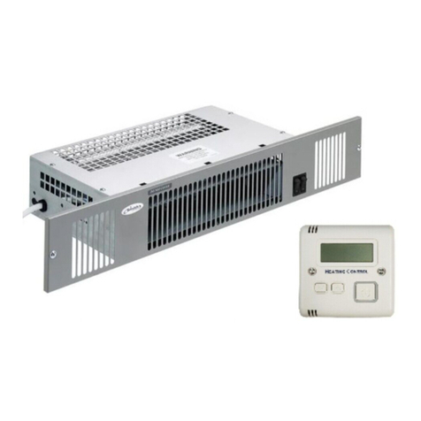
This product is supplied with a wireless battery
powered wall-mounted time and temperature
controller. The product will NOT function without
the wall mounted controller. The controller can
control an unlimited number of heaters.
The controller is primarily designed to minimise
energy wastage and ensure the room is
maintained at the comfort level set by the user.
In the basic setting, the controller is a simple
room thermostat in which the heater will run
until the set temperature is reached. If the room
temperatures falls the heater will switch on again
until the set temperature is reached. The operating
range is between 15°C and 35°C.
1. Choosing a position in a room for the wall
controller. The Controller should be positioned
1.5m above the oor and in the same room
space as the heater. The controller should be
xed to the wall. Avoid areas with draught or
direct sun. Do not position the controller above
or close to the heaters or other heat sources
damp areas or areas where the controller can
be mechanically damaged should also be
avoided. Avoid installing the controller in areas
where there are metal objects between the
heater and the controller. This will reduce the
RF range. The RF range in ideal conditions can
be up to 20m however this can be reduced
when the signal is passing through the walls or
other objects. The range can be also affected
where the controller is mounted close to power
cables, motors or equipment producing strong
electromagnetic eld. If the temperature
control feature is used it is necessary to use one
controller for each room or zone.
2. Installation - The controller is supplied with a
white plastic mounting box that needs to be
xed to a wall at 1.5m above oor level. The
controller is powered by two AAA batteries,
supplied. To activate the controller pull the
plastic tab located at the + battery terminal.
The batteries should be replaced every
12 months.
Check for water leaks. Remove any trapped air
from the system via the vent valve on the top left
hand side of the heat exchanger. Do not over
tighten the air vent.
Installation - controller 2. Controller - Quick Set up
IMPORTANT – THIS HEATER WILL NOT WORK
UNLESS USED AND PAIRED WITH THE SLVTB
THERMOSTAT CONTROLLER
1. Ensure the heater is correctly
installed and connected to the
mains power supply.
DO NOT TURN THE MAINS
POWER ON AT THE WALL
UNTIL INDICATED IN THE
INSTRUCTIONS BELOW.
2. Remove the thermostat from the box and
packaging. Remove the two screws to access
the back of the SLVTB thermostat Controller.
The clear plastic tag should be pulled out from
the end of the battery holder. The screen should
now show the current room temperature.
Note: If you are using any of the advanced
features, these should be set now (see full
instruction detail within Installation and User
Guide)
3. Set the heater fan switch to ON (either normal
or boost) and set the summer winter switch to
Fan (blue)
4. Turn ON the mains power at the wall and
within 20 seconds press and hold the large
ON/OFF button on the SLVTB thermostat
controller, keep pressing button, PAIR and
then TEST will appear on the screen.
Once TEST appears on the screen release the
button and the fan in the heater should run.
ONON
OFF
Fan Switch to ON
Normal
Off
Boost
Heating
(red)
Fan
(blue)
