Mounting the Camera4
Introduction
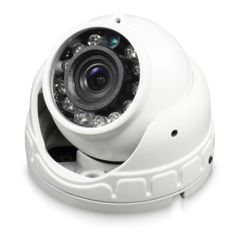
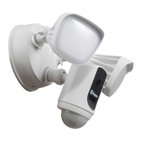
Congratulations on the purchase of your Swann En-
forcer™ Dome Security Camera.
• 1080p Full HD video with sensor spotlight plus
red & blue flashing lights
• True Detect™ Heat & Motion sensing for reli-
able alerts
• Powerful Night2Day™ color night vision
• Works in rain & snow all year round
• Reliable BNC cable connection
Important instructions
1. Make sure the camera is fixed correctly and stable
if fastened in place.
2. Never place strain of any kind on the network ca-
ble connection. It’s designed to clip into the Ethernet
port, but it won’t support weight and can be broken.
3. Do not operate if wires and terminals are exposed.
Important Note: All jurisdictions have specific laws
and regulations relating to the use of cameras. Be-
fore using any camera for any purpose, it is the buy-
er’s responsibility to be aware of all applicable laws
and regulations that limit the use of cameras.
About this Manual: The content in this manual is for
information purposes only and is subject to change
without notice. While every effort is made to ensure
that this manual is accurate at the time of printing, no
liability is assumed for any errors occurred.
1
For instructions on how to configure your camera
for motion detection, changing image settings,
and other functions available, please consult the
manual for your DVR. Go to support.swann.com,
search for your model, then download.
The camera can be mounted onto a flat vertical or horizontal surface
and must be of sufficient strength to hold the camera.
Step 1: Press the button (1) to release the dome enclosure and the
dome camera from the mounting bracket.
Mounting the Camera3
Step 2: You will see a black cable (2) connected to the camera, which
in turn is connected to the camera bracket’s black cable.
Rotate the seal cap (3) clockwise and gently pull apart the connection
to disconnect. Remove the dome camera from the camera bracket.
1
2
2
3
Step 3: Position the mounting bracket in the location you want to
mount the dome camera to. Using a pencil or magic marker, mark
the mounting holes (4) and hole (5) for the camera’s cable.
Use a hole saw that you can attach to a drill to make a hole for the
cable. A large drill bit can also be used.
(continued on next page)
44
4
5
Step 4: Using the appropriate screws for the surface you are
mounting to, secure the bracket in place. If mounting to a wooden
surface, screw the bracket directly to the surface. If mounting to a
masonry surface (brick or concrete), you’ll need to use the supplied
wall plugs.
Step 5: Connect the Video & Power Cable to the corresponding
connections on the camera’s cable. Reconnect the black cable on the
camera to the black cable connected to the bracket. Rotate the seal
cap anti-clockwise to tighten.
Sit the dome camera onto the camera bracket (as shown above right),
then place the dome enclosure into the camera bracket and lock it
in place. The camera can be rotated left or right (rotate the camera
bracket left or right as well) or up and down. Check the image on your
DVR and make adjustments as necessary.
Connecting the Camera2
1. Connect the video output and pow-
er input connections on the camera to
the corresponding connections on the
supplied video & power cable.
2. Connect the supplied power split-
ter to the power input on the video &
power cable (repeat this step if multi-
ple cameras are included).
3. Connect the supplied power adapt-
er to the other end of the power split-
ter then connect the power adapter to
a spare wall socket.
4. Connect the video output on the
video & power cable to an available
camera input on your DVR. Twist the
connection to lock it in place.
For single camera packs, connect the supplied power adapter
directly to the power input on the video & power cable.
2 3
Power Input
Video Output
1
Twist to lock
connectors
Video Input
Video & Power Cable
Connect this to your DVR
Power Splitter
connects here
Power Output
Power Adapter
connects here
Power Splitter
Power Adapter
Video & Power Cable
connects here
Connect to a spare
power outlet
LANLAN
VGAVGA
7531
8 6 4 2
VIDEO INPUTVIDEO INPUT AUDIO
OUTPUT
AUDIO
OUTPUT
AUDIO
INPUT
AUDIO
INPUT
3 1
4 2
12V12V
RS485RS485
4
