Specifications are subject to alteration without notice.
10 www.swegon.se
4 ELECTRICAL WIRING
Important!
The installation work shall be carried out by an authorized
electrician.
4.1 Wiring to the mains power
The power cable must be arranged through the front
panel of the unit. A permanent cable gland has been fac-
tory-fitted to the side of the inspection door.
The location of the gland varies slightly depending on the
size of cooling unit.
The incoming cable for 400 V power (5-wire system) must be
connected directly to the safety switch, which has four nor-
mally-closed contact functions. The safety switch is installed
in the built-in electrical cubicle. The terminal block for incom-
ing earth is situated adjacent to the safety switch.
If a 4-wire system is used, a jumper should be fitted be-
tween the earth and zero terminal blocks in the Cooler.
For access to the connections of the safety switch, the
safety guard above the electrical cubicle components has
to be dismantled.
4.1.1 Size 14 Coolers
The cable gland is located to the right at the top of the
front panel.
The fuse for the cable shall be rated for 20 A(T).
When sizing the cable, take into account the ambient tem-
perature and how the cable will be arranged.
See Fig. 10.
4.1.2 Size 18 Coolers
The cable gland is located at the bottom edge of the front
panel.
Fuse for the cable should be rated for 25 A(T). When sizing
the cable, take into account the ambient temperature and
how the cable will be arranged.
See Fig. 10.
4.1.3 Size 24 and 34 Coolers
The cable gland is located uppermost and to the right on
the front panel.
The fuse for the cable shall be rated for 32/35 A (T) for the
size 24 Coolers and 35 A(T) for the size 34 Coolers. When
sizing the cable, take into account the ambient temperature
and how the cable will be arranged.
See Fig. 10.
4.1.4 Cooler sizes 48 - 60
The cable gland is located uppermost and to the right on
the front panel.
The fuse for the cable shall be rated for 63 A(T). When siz-
ing the cable, take into account the ambient temperature
and how the cable will be arranged.
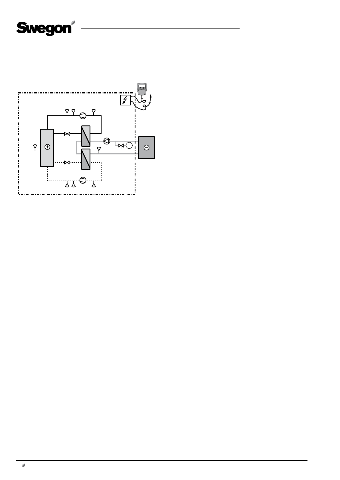
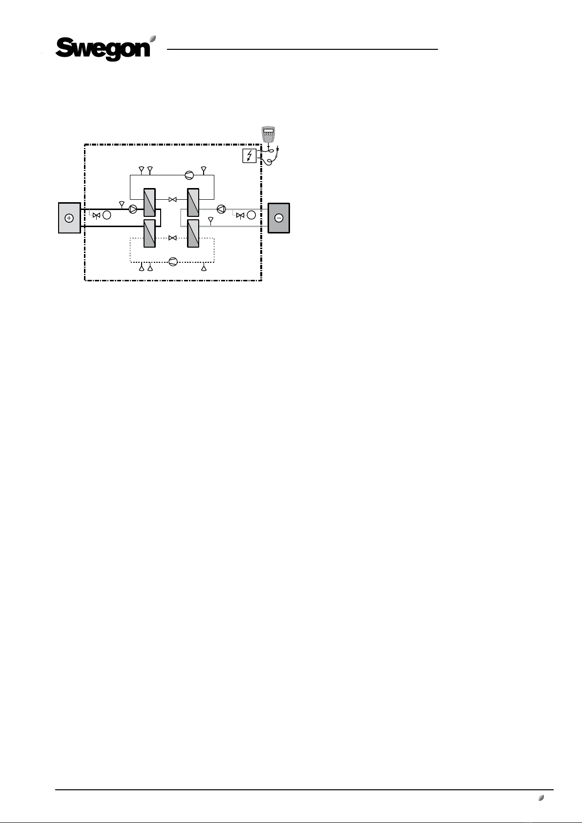
Fig. 10
4.2 Other electrical connections
4.2.1 GOLD, Version B
General
The Cooler is supplied with two alternative accessories for
controlling the cooling load.
Extra interference protection is required for the Cooler
variants operating where the cooling load is controlled by
an external 0 –10 V DC signal.
To meet the provisions stipulated in the EMC Directive,
concerning insensitivity to interference, the analogue
inputs must be protected by a Ferrit block, 019 210.
Communication cable 019 007 is the accessory, that must
be used when the Cooler operates together with the
Version B GOLD ventilation unit. See the individual instruc-
tions.
Design
The ferrit block, 019 210, is designed for snapping
around wires.
The block consists of two ferrit-halves, enclosed in a
plastic casing that can be opened.
The plastic casing has ”hinges” and a simple lock that make
it easy to open and close around relevant wires.
Dimensions: H = 15 mm, W = 15 mm, L = 29 mm and
diameter of the openings = 6.6 mm.
Communication cable 019 007 is a 5 m long flat cable,
with a type RJ 1 modular connection fitted at both ends.
The cable transfers normal communication signals bet-
ween the control unit and the GOLD unit (Version B), but
not 4 V DC. Both types of control have their own 4 V DC
supply.
Important: Do not use an ordinary bus cable! If the 4 V DC
connections are interconnected, this will cause malfunc-
tions.