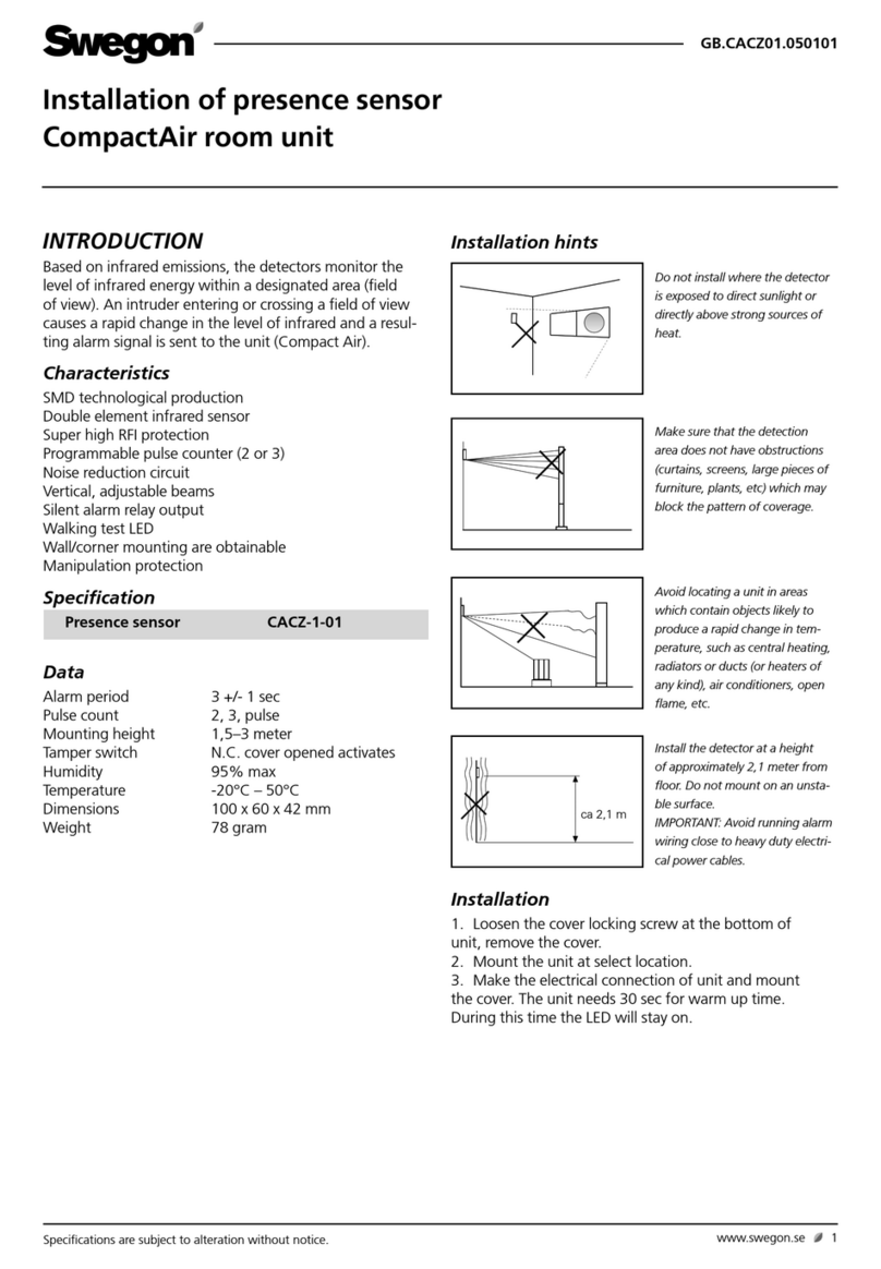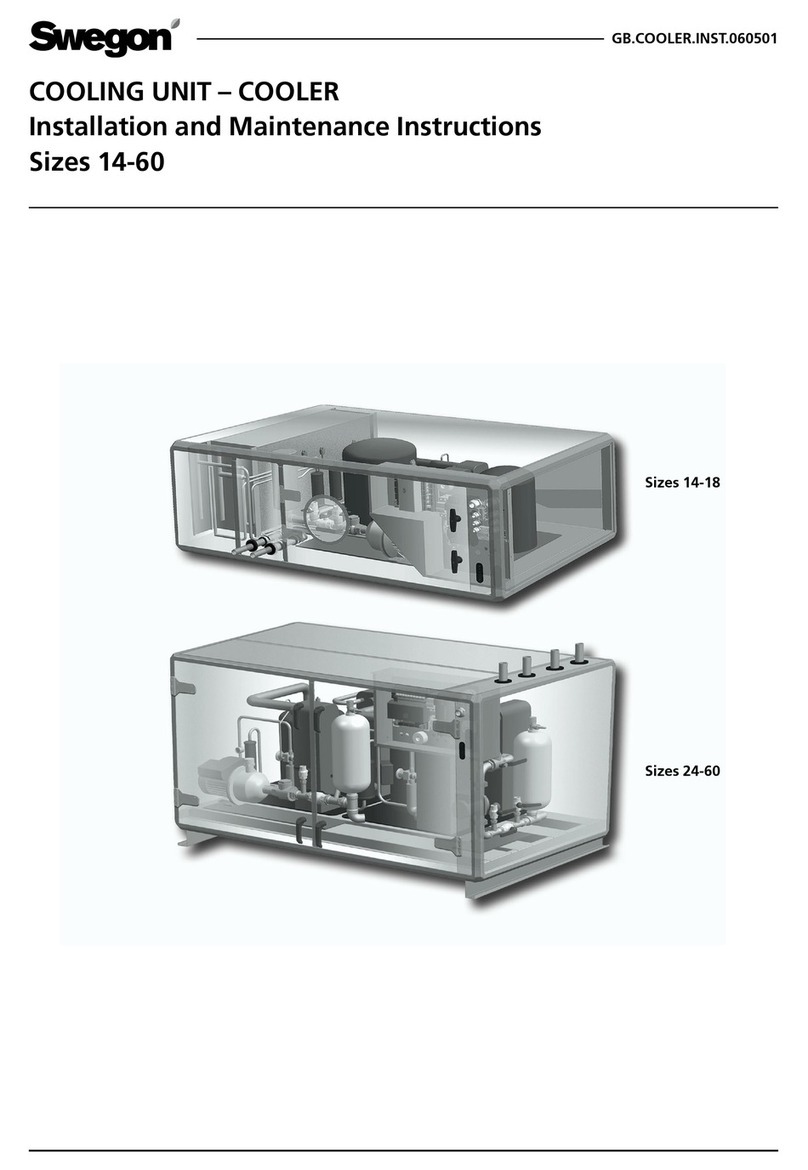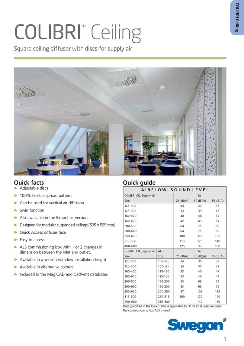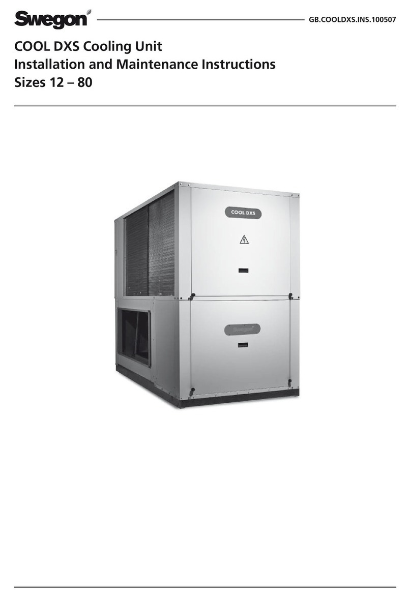
SRH.131218
We reserve the right to alter specifications. | Änderungen vorbehalten. 7www.swegon.com
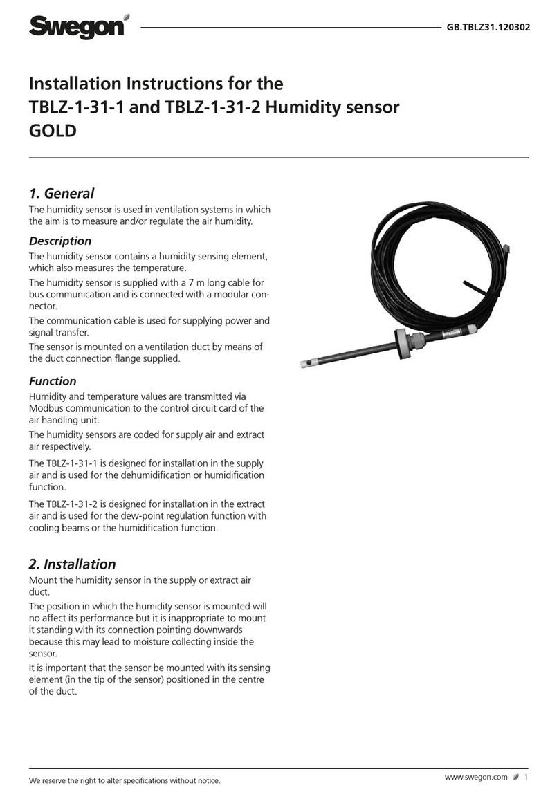
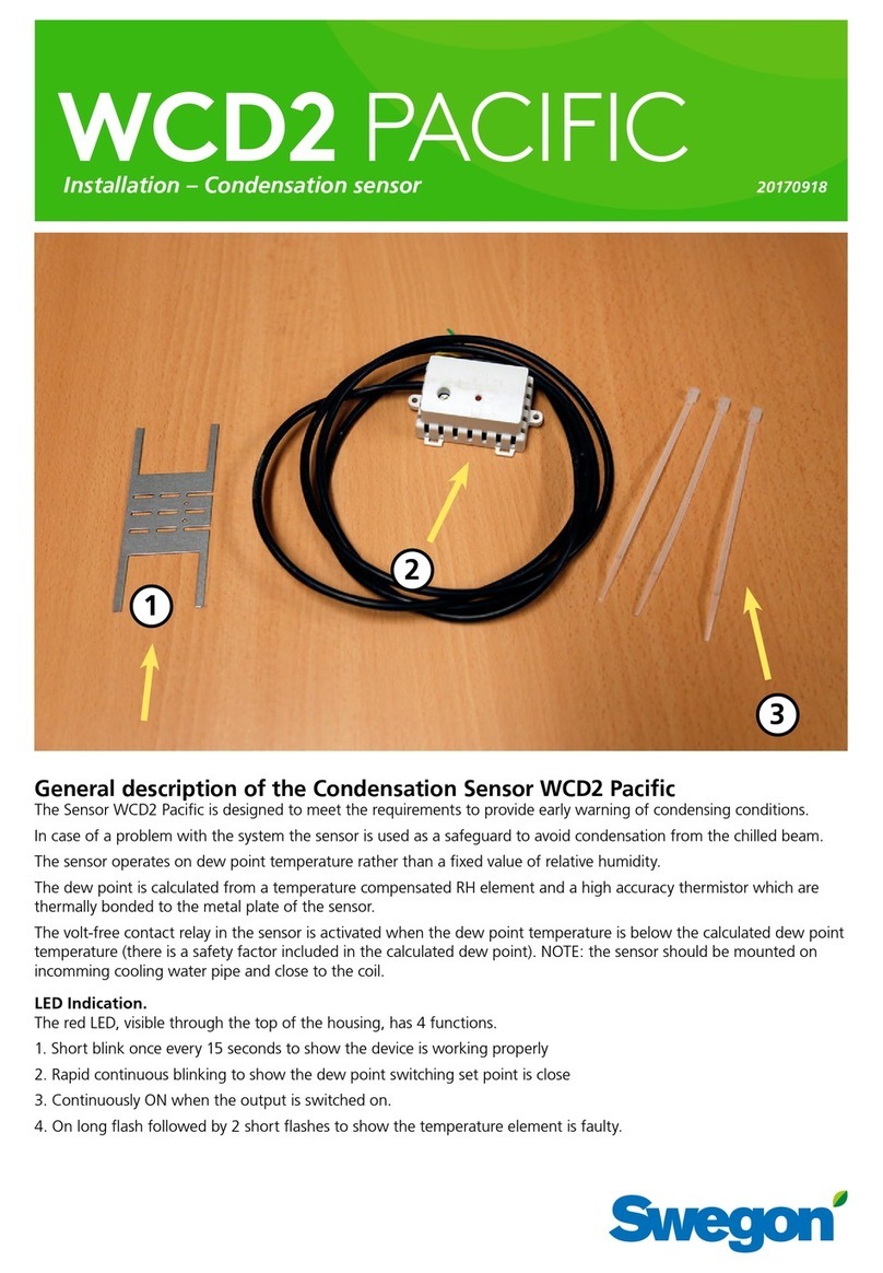
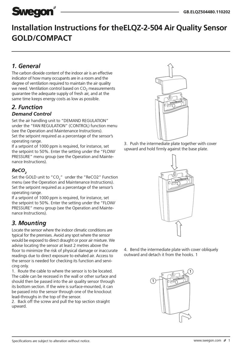
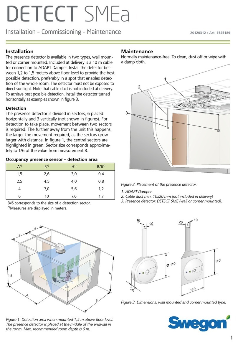
Installation der Fühlereinheit im Gerät
Lösen Sie die Befestigung für das Fühlerkabel im Gerät.
Verbinden Sie das Kabel dann mit dem Steckverbinder (1)
an der Fühlerplatine. Drücken Sie die Platine an ihrer
Position in der Grundplatte (2) der Fühlereinheit ein.
Drücken Sie das Verschlussteil (3) an der Grundplatte ein
und verschrauben Sie (4) die Fühlereinheit in der Öffnung
im Gerät, von der das Kabel zuvor entfernt wurde.
3. Inbetriebnahme
Die Inbetriebnahme erfolgt über das
Smart-Bedieneinheit.
Nach der Installation der Fühlereinheit erkennt das
Lüftungsgerät die verfügbaren Fühler automatisch. Die
Funktionen für die installierten Fühler werden im Menü
Smart-Funktionen an einer Smart-Bedieneinheit ange-
zeigt. Die gewünschten Funktionen werden über das
Menü Smart-Funktionen ausgewählt und gemäß der
Bedienungsanleitung für das Lüftungsgerät eingestellt.
Installation of Sensor package in the unit
Loosen the clip securing the sensor cable in the ventila-
tion unit. Now connect the cable to connector (1) on
the sensor’s circuit card. Press the circuit card into posi-
tion on the base plate (2) in the Sensor package. Press
on the cover section (3) on the base plate and screw
the (4) Sensor package in the hole in the unit, from
where you loosened the cable earlier.
3. Commissioning
Commissioning is done with the Smart control panel.
When the Sensor package is installed the ventilation
unit will identify the sensors automatically. The functions
corresponding to the installed sensors will be visible in
the menu Smart functions on a Smart control panel. The
functions required are selected from the menu Smart
functions and are set according to the ventilation unit’s
user guide.
1
3
4
2
W3, W4, W5, W9, R3 and R5 ventilation
units are available as left-hand and right-
hand model. Location of the Sensor packa-
ge is presented in right-hand model units
in this instruction. Position in the left-hand
units is the same but on the opposite side
of the unit. Left-hand unit is the mirror
image of the right-hand unit.
W3, W4, W5, W9, R3 und R5 Lüftungsgeräte
sind als Links- oder Rechtsausführung
erhältlich. Auf den Abbildungen in
der Anleitung wird die Position der
Fühlereinheit in Rechtsausführungen dar-
gestellt. Linksausführungen weisen eine
entsprechende Position auf – allerdings
auf der gegenüberliegenden Geräteseite.
Linksausführungen sind spiegelverkehrt zu
Rechtsausführungen angeordnet.
