Swegon TBIQ-2-1-aa IQnomic Plus GOLD User manual

GB.TBIQ2480.190318
We reserve the right to alter specifications. www.swegon.com 1
L1 L2
1632457 12981011
13 181514 16 17 19 242120 22 23
4
5
6
7
8
9
A
B
C
D
E
F
0
1
2
3
Installation Instructions for the
TBIQ-2-1-aa IQnomic Plus Module
GOLD/COMPACT
1. General
The IQnomic Plus is used for extra functions for which
inputs and outputs are not included as standard in the
control unit of the air handling unit.
2. Installation
Mount the IQnomic Plus at a suitable location. One helpful
hint is to mount the module at an unoccupied spot on the
rail inside the control cubicle of the air handling unit.
Wire the IQnomic to the control unit inside the electrical
equipment cubicle of the air handling unit.
Connect the communication cable, supplied with the unit,
to one of the connections on the module. It is not im-
portant which connection is used. The reason why there
are two connections is to make it possible to connect seve-
ral IQnomic in series.
Connect the other end of the communication cable to one
of the connections of the control unit, marked Internal
EIA-485.
Function selector switch
0 ReCO2(Intermittent night-time heating + extra control
sequence)* or Input/Output connections***
1 Coil heat exchanger*
2 Plate heat exchanger*
3 External supervision
4 Humidification*
5 AQUA Link*
6 External Cooling Control
7 All Year Comfort
8 Swegon Factory*
9 Preheater**
A Xzone heating*(see separate instructions TBLZ-1-50)
B Xzone heating*(see separate instructions TBLZ-1-50)
C Spare
D Spare
E Enhanced heating sequence*
F Spare
* Not COMPACT/GOLD LP
** Not COMPACT Air/Heat
*** Do not apply to GOLD RX/PX/CX/SD
3. Data
Terminal contacts: 2 x RJ 12 6/6
Voltage supply
(Via modular contact): 24V DC
Relay contacts 5A/AC3
12A/AC1
Ambient temp.
Normal: -20 °C — 40 °C, 10 — 95 % RH
Degree of protection: IP 20 to EN 60529
CE approval: EN 61000-6-2, EN 61000-6-3
Function
selector
switch
Figure 1
Terminal number
1
2
4
5
7 →
8 –
9 →
10 –
11 +
12 – *
13 – *
14 +
15 – *
16 +
17 – *
18 +
19 – *
20 +
21 –
22 s
23 –
24 s
* Measuring zero. Internally connected.
Relay 1
Relay 2
Digital, IN 1
Digital, IN 2
External power supply, 24 V DC
0–10 V, OUT 2
0–10 V, OUT 1
0–10 V, IN 2
0–10 V, IN 1
Digital sensor 2
Digital sensor 1

GB.TBIQ2480.190318
We reserve the right to alter specifications.
1632457 12981011
13 181514 16 17 19 242120 22 23
L1 L2
4
5
6
7
8
9
A
B
C
D
E
F
0
1
2
3
132
20
21
60
61
4. Function
4.1 ReCO2
The IQnomic Plus module is used for the ReCO2 function
(function selector switch set to position 0, see Figure 1).
The function is activated in the GOLD unit’s hand terminal
or via the communication interface.
The module controls mixture and outdoor air dampers.
Connect signal response from the mixture damper’s actua-
tor to terminal 18 (+) on the module. Do not connect
outdoor air damper’s signal response, monitoring is carried
out by the unit’s flow alarm.
Connect the control signal for the mixture damper’s actua-
tor to terminal 14 (+) on the module. Connect the control
signal for the outdoor air damper’s actuator to terminal 6
(+).
If the function is to be controlled from an external CO2
sensor, or similar with signal 0- 0 VDC, connect it to termi-
nal 9 (-) and 20 (+).
Intermittent night-time heating + extra control se-
quence
The module can also be used for a combination of the in-
termittent night-time heating and extra control sequence
functions (function selector switch in position 0, see Fig.
1).
Connect the air recirculation damper just like you would
for the ReCO2, see Fig. 2.
Fig. 2
GOLD
Control unit
* 24 VAC supply can be connected to the unit’s control unit, terminal 60
(G) and 61 (G0).
Applies to GOLD size 100/120 only:
If the total load on wiring terminals 58-59 and 60-61 is higher than 16
VA,you should wire the leads to terminals 201 (G) and 202 (G0). Wiring
terminals 201-202 can be loaded with a total of max. 48 VA.
** See the appropriate instructions for CO2 sensors from Swegon, ELQZ-
2-504 or ELQZ-2-504-2.
*** If the outdoor air damper does not have spring return, it is not
necessary to wire the 24 V (G) supply voltage across the control relay
(20-21).
Recirculation damper/
Internal damper
Outdoor air damper/External damper
CO2sensor**
ELQZ-2-504
The function
selector switch
must be set to
the 0 position
*
***
2 www.swegon.com

GB.TBIQ2480.190318
We reserve the right to alter specifications. www.swegon.com 3
4.2 Input/Output connections
The IQnomic Plus is used for the Input/Output connection
function (function selector switch in position 0. See Figure
1).
The function can be activated in the hand-held air han-
dling unit’s micro terminal.
The GOLD LP/COMPACT has as standard two inputs and
two outputs respectively. In applications in which this is
not sufficient, the IQnomic Plus module can be used for
increasing the number of inputs and outputs to 4 respec-
tively.
Outputs
When the IQnomic Plus module is used, a maximum of
four of the functions stated below can be combined as
standard.
Optional functions:
- Damper, output: For control of the outdoor air/exhaust
air damper.
- Operation, output: Indicates that the unit is operating.
- Low speed, output: For indicating low speed operation.
- High speed, output: For indicating high speed operation.
- A Alarm, output: For type A group alarms.
- B Alarm, output: For type B group alarms.
- Heating, output: For controlling external heating.
- Cooling, output 1: For controlling external cooling.
- Cooling, output 2: For controlling external cooling.
Inputs
When the IQnomic Plus module is used, a maximum of
four of the functions stated below can be combined as
standard.
Optional functions:
– External stop: The unit will stop if the input is not closed.
– External LS: For external overtime operation via timer
(switch clock), from stop to low speed operation.
– External HS: For external overtime operation via timer
(switch clock), from stop or low speed operation to high
speed operation.
– External Alarm 1: For connection of External Alarm 1.
– External Alarm 2: For connection of External Alarm 2.
– External reset: For connection of the pushbutton for
resetting a tripped alarm.
– External fire alarm: A fire alarm will trip if the input is not
closed.

GB.TBIQ2480.190318
We reserve the right to alter specifications.
4 www.swegon.com
4.3 Coil heat exchanger
The IQnomic Plus module is used for the coil heat exchan-
ger function.
An IQnomic Plus module is installed, as standard, in all
GOLD CX air handling units. The IQnomic Plus module’s
function selector switch is set to Position 1.
The module controls the circulation pump of the pipework
package and the valve actuator on the coil heat exchan-
ger.
A limiting sensor is connected to the module. Readings
from the temperature sensor (strap-on type) prevent the
water circulating through the extract air coil from reaching
such low temperatures that freezing is likely.
The GOLD CX unit requires communication with an IQno-
mic Plus module (1) so that no alarm will trip.
The contactor for controlling the circulation pump is con-
nected to terminals 1 and 2 on the module.
Signal response from the contactor is connected to termi-
nals 7 and 8 on the module.
The control signal (Y) for the valve actuator is connected
to terminal 6 (+) on the module.
The valve position signal (U) is connected to terminal 20
(+) on the module.
The conductors for supplying 24 V AC power to the valve
actuator must be connected to Terminals 203 (G0) and
204(G). A jumper must be fitted between Terminal 12 on
the module and Terminal 203 (GO) to give reference to
control signals.
Connect the temperature sensor conductors to Terminals
24 (white wire) and 23 (brown wire).
1632457 12981011
13 181514 16 17 19 242120 22 23
101 203
204
102
L1 L2
4
5
6
7
8
9
A
B
C
D
E
F
0
1
2
3
Contactor C1, conn. A1
Contactor C1, conn. 13
Contactor C1, conn. 14
Valve
actuator
Temp.
sensor*
Green
Brown
Yellow
White Brown
White
4.4 Plate heat exchanger
The IQnomic Plus module is used for the plate heat
exchanger function.
An IQnomic Plus module is installed, as standard, in all
GOLD PX air handling units. The IQnomic Plus module’s
function selector switch is set to Position 2.
The module controls the by-pass and shut-off damper
actuators on the plate heat exchanger.
Two limiting sensors are connected to the module.
Readings from the temperature sensor (strap-on type)
prevent the temperature in the foil, in the extract air pas-
sages of the heat exchanger cube, from reaching such low
temperatures that freezing is likely.
The GOLD PX unit requires communication with an IQno-
mic Plus module (2) so that no alarm will trip.
The control signal (Y) for the damper actuator is connec-
ted to terminal 6 (+) on the module.
The damper actuator signal response (U) is connected to
terminal 20 (+) on the module.
The conductors for supplying 24 VAC power to the valve
actuator must be connected to Terminals 201 (G0) and
202(G). A jumper must be fitted between Terminal 12 on
the module and Terminal 201 (GO) to provide reference to
the control signals.
Connect the conductors of the one temperature sensor
to Terminals 24 (white wire) and 23 (brown wire); those
of the other sensor to Terminals 22 (white wire) and 21
(brown wire) with the other.
1632457 12981011
13 181514 16 17 19 242120 22 23
201
202
L1 L2
4
5
6
7
8
9
A
B
C
D
E
F
0
1
2
3
Damper
actuator Temp.
sensor 1*
Black
Red
Grey
Pink Brown
White
Temp.
sensor 2*
Brown
White
Fig. 3
Fig. 4
* Digital temperature sensors require correct polarity. Be careful
when you wire the conductors.

GB.TBIQ2480.190318
We reserve the right to alter specifications. www.swegon.com 5
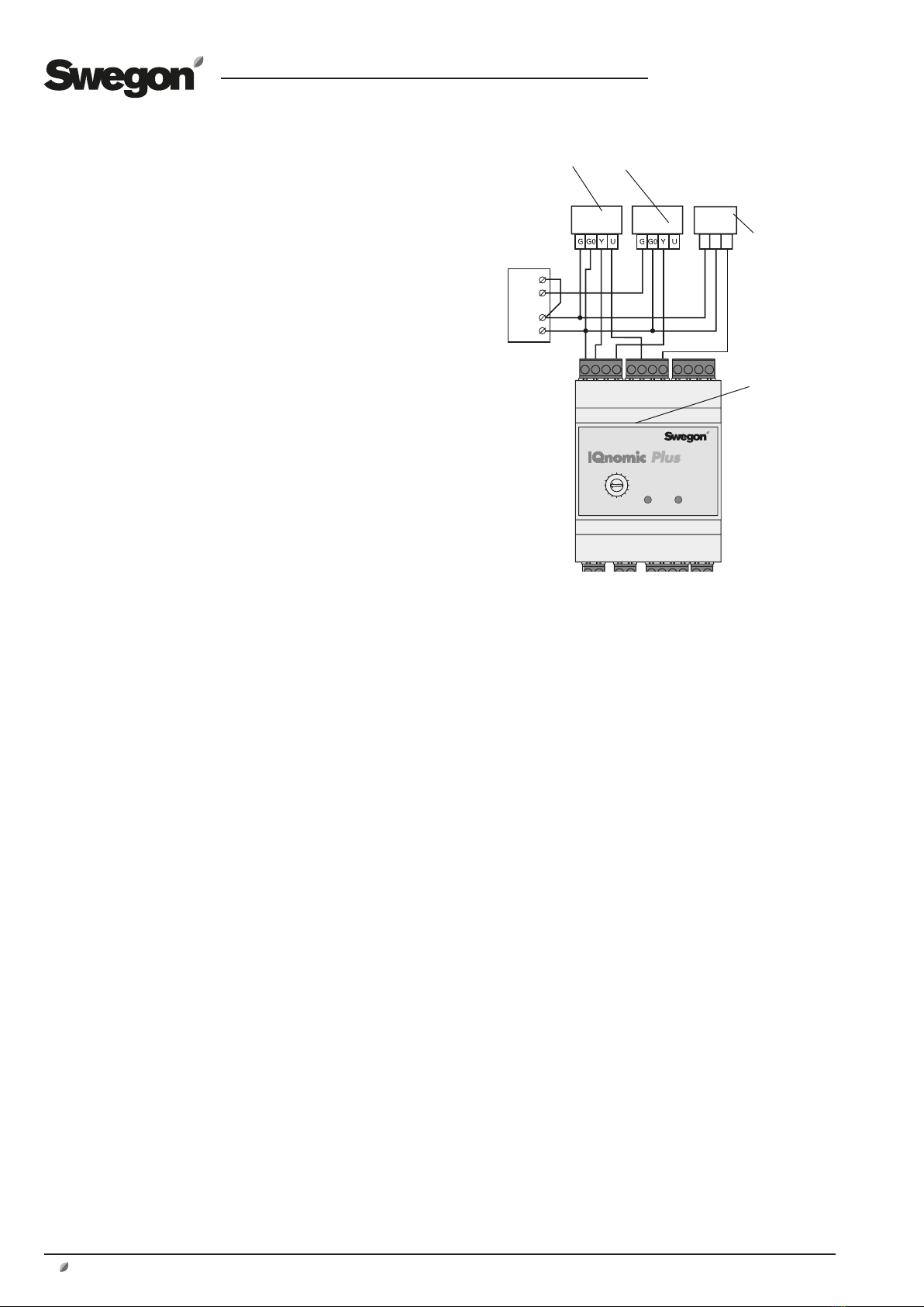
4.5 External supervision
The IQnomic Plus module is used for external supervision
by means of analogue and digital signals (function selector
switch set to position 3, see figure) when regular means
of communication with the air handling unit cannot be
used. The module is, for example, suitable for use if the air
handling unit is to be controlled/supervised via a computer
substation or a PLC system.
The function can be activated in the terminal of the unit or
via a communication interface.
Relay 1 Connects between Terminals 1 and 2
when the control unit, in the terminal,
indicates Selected function*, active
Factory-preset function: Heating by
means of heat exchanger required.
Relay 2 Connects between Terminals 4 and 5
when the control unit, in the terminal,
indicates Selected function*, active.
Factory-preset function:
Cooling required.
* Two of the functions below may be indicated:
All GOLD/COMPACT units
Cooling Boost, Heating Boost, Cooling demand, HRC
heating demand, Reheating demand, Supply airflow
regulation to lower rate, Reduction in electric air
heater output, Intermittent night heating, Summer
night cooling, Morning Boost, HRC defrosting.
GOLD RX/PX/CX/SD only
Extra heating control sequence, Extra cooling control
sequence, Damper relay, Operation relay, Auto
operation, Manual operation.
Digital In 1 Connect to terminals 7 and 8.
The following functions can be selected in
the hand-held micro terminal:
- Alarm reset. Resets possible alarms on
closure.
- External stop of the AYC cooling water
flow regulation system. Blocks the cooling
water flow regulation and pump function
when the input is interrupted.**
- External stop of the AYC cooling water
flow regulation system. Blocks the heating
water flow regulation and pump function
when the input is interrupted.**
Factory preset function: Alarm reset.
Digital In 2 Connect to terminals 9 and 10.
The following functions can be selected in
the hand-held micro terminal:
- Alarm reset. Resets possible alarms on
closure.
- External stop of the AYC cooling water
flow regulation system. Blocks the cooling
water flow regulation and pump function
when the input is interrupted.**
- External stop of the AYC cooling water
flow regulation system. Blocks the heating
water flow regulation and pump function
when the input is interrupted.**
Factory preset function: Alarm reset.
** GOLD RX/PX/CX/SD only
Digital sensor 1 Spare
Digital sensor 2 Spare
0 - 10 V In 1 Spare
0-10 V In 2 Spare
0 - 10 V Out 1 Indicates the present supply airflow,
from 0 to the AHU fans’ max speed.
0 - 10 V Out 2 Indicates the present extract airflow,
from 0 to the AHU fans’ max speed.

GB.TBIQ2480.190318
We reserve the right to alter specifications.
6 www.swegon.com
Fig. 5
4.6 Humidification
Steam humidifier
Select Humidification in the AHU hand-held micro termi-
nal or via a communication interface (function selector
switch set to position 4; see Fig. 1).
Use relay output DO 1 (Terminals 1-2) for controlling the
steam humidifier, on/off.
Digital input (Terminals 7-8) can be used for external
alarms. Select normally open or normally closed contact
function in the AHU hand-held micro terminal.
Use the analogue output AO 1, Terminals 15 (-) and 16
(+), for variably modulating 0 – 10 V to the steam humidi-
fier.
L1 L2
1632457 12981011
13 181514 16 17 19 242120 22 23
4
5
6
7
8
9
A
B
C
D
E
F
0
1
2
3
Steam humidifier (not
Swegon)
Alarms**
0-10 V In
Start -
Stop*
+ -
Evaporative humidification
Select Humidification in the AHU hand-held micro termi-
nal (function selector switch set to position 4; see Fig. 1).
Relay output DO 1 (use Terminals 1-2) for controlling the
humidifier’s solenoid valve or circulation pump, on/off.
L1 L2
1632457 12981011
13 181514 16 17 19 242120 22 23
4
5
6
7
8
9
A
B
C
D
E
F
0
1
2
3
Fig. 6
Solenoid valve or circulation
pump, evaporative humidifier
(not Swegon)
* Normally-open contact start the humidifier.
** Select the normally-open contact function in the AHU hand-held
micro terminal.
Supply
voltage

GB.TBIQ2480.190318
We reserve the right to alter specifications. www.swegon.com 7
4.7 AQUA Link
Select AQUA Link in the AHU’s hand-held micro terminal
or via a communication interface (function selector switch
set to position 5; see Fig. 1).
Use relay output DO 1 (Wiring terminals 1-2) for control-
ling the circulation pump.
Digital input (Wiring terminals 7-8) can be used for pump
alarms. Select normally open, normally closed or contactor
function in the AHU’s hand-held micro terminal.
1632457 12981011
13 181514 16 17 19 242120 22 23
L1 L2
4
5
6
7
8
9
A
B
C
D
E
F
0
1
2
3
Bild 7
Circulation pump
Pump alarm

GB.TBIQ2480.190318
We reserve the right to alter specifications.
8 www.swegon.com
4.9 All Year Comfort
The IQnomic Plus is used for the All Year Comfort func-
tion, (function selector switch set to position 7, see Figure
1).
See the All Year Comfort Function Guide and the Installa-
tion instructions for the TBLZ-1-59 equipment cubicle
4.10 Swegon Factory
The IQnomic Plus module is used for the Swegon Factory
function (function selector switch set to position 8, see Fi-
gure 1) where type BOOSTER low-velocity supply air termi-
nals with damper motor are used. Relay 1 on the module
is energized whenever the supply air temperature is higher
than the room temperature; relay 2 operates inversely
compared to relay 1, i.e. when relay 1 is energized, relay 2
is de-energised and vice versa. For wiring particulars, see
Figure 9.
Fig. 9
G0
G 24 VAC
MM
01
02
Swegon
ASM115SF901
1 632 4 5 7 1298 10 11
13 181514 16 17 19 242120 22 23
L1 L2
4
5
6
7
8
9
A
B
C
D
E
F
0
1
2
3
Actuator for
the BOOSTER
4.8 External cooling control of the COM-
PACT and GOLD
Select external cooling control in the hand-held micro
terminal of the air handling unit (function selector switch
set to position 6, see Figure 1).
When the IQnomic Plus module is used for control-
ling other types of cooling circuit valves or cooling units
(external cooling control), the inputs must be fitted with a
jumper (if they are not used for external alarms). Jumpers
must also be fitted from terminal block 14 to terminal
block 20 and terminal block 18 (if they are not used for
external in-service pressure switches).
IQnomic Plus Module Number 6 must be manually activa-
ted in the hand-held micro terminal.
Relay outputs, DO 1 (terminal block 1-2) and DO2 (ter-
minal block 4-5) are used for on/off controlling of the
cooling units or the circulation pump in the cooling water
circuit.
The digital inputs, DI 1 (terminals 7-8) and DI 2 (terminals
9-10), can be used for external alarms with normally-
closed function (alarms 85 – 86).
The AO 1 analogue output (terminal block 15 (+)) is used
for modulating 0-10 V to the actuator for the cooling
circuit valve or the cooling unit with capacity regulation.
The AO 2 analogue output (terminal block 14 (+)) is used
for modulating 5 V as a reference for supervising the in-
service pressure switches, for instance, via analogue inputs
AI 1 and AI 2. 0V in on input AI 1 stops output DO 1 and
0 V in on input AI 2 stops output DO 2. Each relay is ener-
gised when the input has 5 V in again and the restarting
time has expired.
1632457 12981011
13 181514 16 17 19 242120 22 23
L1 L2
4
5
6
7
8
9
A
B
C
D
E
F
0
1
2
3
9
GOLD LP/
COMPACT
GOLD
RX/PX/CX/SD
10
60 61
Valve actuator,
cooling
Type 24 V AC or 0-10
V DC
Circulation pump
alt. Compressor 1
Compressor 2
Fig. 8
G G0 Y
Control
unit
Applies to GOLD size 100/120 only:
If the total load on wiring terminals
58-59 and 60-61 is higher than 16
VA,you should wire the leads to ter-
minals 201 (G) and 202 (G0). Wiring
terminals 201-202 can be loaded
with a total of max. 48 VA.

GB.TBIQ2480.190318
We reserve the right to alter specifications.
4.11 Preheater
The IQnomic Plus module is used for the preheating func-
tion (function selector switch set to position 9, see Figure
1).
The function is activated in the GOLD unit’s hand terminal
or via the communication interface.
The module controls an air heater for water (fig. 10) or an
electric air heater (fig. 11)
Wiring the TBLA/TCLA air heater, water, for the
GOLD, or electric air heater of a type other than Sw-
egon standard
Connect control signal 0-10 VDC for the electric air heater
or valve actuator to terminals 5 (-) and 6 (+).
Connect any pumps to terminals 1 and 2.
Connect any anti-frost sensors for the water air heater to
terminals 21 and 22. If an electric air heater is used, clo-
sure must be obtainable from potential-free contacts.
Connect temperature sensors (TBLZ-1-30) for preheating
to terminals 23 and 24.
www.swegon.com 9
* 24 V AC power can be connected to Termi-
nals 60 (G) and 61 (G0) on the controller
of the air handling unit.
Applies to GOLD size 100/120 only:
If the total load on wiring terminals 58-59 and
60-61 is higher than 16 VA,you should wire
the leads to terminals 201 (G) and 202 (G0).
Wiring terminals 201-202 can be loaded with
a total of max. 48 VA.
** Digital temperature sensors require correct
polarity. Be careful when you wire the con-
ductors
1632457 12981011
13 181514 16 17 19 242120 22 23
L1 L2
4
5
6
7
8
9
A
B
C
D
E
F
0
1
2
3
Temp. sensor,**
for preheated air
24 VAC*
Valve actuator
G G0 Y
Temp. sensor,**
anti-frost monitor
Control of the
circulation pump
T1
GR
R1
RD
Jack for wall moun-
ting, 019611
Brown
White
–S–S
Fig. 10

GB.TBIQ2480.190318
We reserve the right to alter specifications.
10 www.swegon.com
Connection of standard
air heater to GOLD, TBLE/TCLE
Standard TBLE/TCLE coils are fitted with quick coupling for
connection to control cable. Connect the quick-fit connec-
tor to the adaptor (TBLZ-1-55) and from there further with
loose cables as shown in Figure 10 or, as an alternative,
clip off the control cable beside the quick-fit connector
and peel approx. 100 mm of insulation from the cable.
– Connect white/orange or white wire to Terminal 21.
– Connect blue wire to Terminal 22.
– Connect white/blue or light blue wire to Terminal 15.
– Connect orange wire to Terminal 16.
Other wires are not used to connect air heaters for pre-
heating.
Fig. 11
** Digital temperature
sensors require cor-
rect polarity. Be careful
when you wire the
conductors.
1632457 12981011
13 181514 16 17 19 242120 22 23
L1 L2
4
5
6
7
8
9
A
B
C
D
E
F
0
1
2
3
Temp. sensor,** for preheated air
0-10 V
Electric air
heater Swe-
gon Standard
with control
cable, 8-pole
G0
Overheating
protection
–S–S
R1
RD
BL
OR
BK
RD
WH
BR
YL
GR
T1
GR
Jack for wall moun-
ting, 019611
Adaptor for wall mount-
ing, 8-pin, TBLZ-1-55
(G0)
(G)
24 V AC*
Applies to GOLD size 100/120 only:
If the total load on wiring terminals 58-59
and 60-61 is higher than 16 VA,you should
wire the leads to terminals 201 (G) and
202 (G0). Wiring terminals 201-202 can be
loaded with a total of max. 48 VA.

GB.TBIQ2480.190318
We reserve the right to alter specifications. www.swegon.com 11
1632457 12981011
13 181514 16 17 19 242120 22 23
L1 L2
4
5
6
7
8
9
A
B
C
D
E
F
0
1
2
3
4.12 Enhanced heating sequence
The IQnomic Plus is used for enhanced heating sequence
(function selector switch set to position E; see Fig. 1).
The function can be activated in the hand-held micro ter-
minal of the GOLD unit or via a communication interface.
The module controls the air heater for hot water (Fig. 12)
or electric air heater (Fig. 13).
To wire the TBLA/TCLA air heater, water, for the
GOLD, or electric air heater of a type other than Sw-
egon standard
Connect the 0-10 V DC control signal conductors for
signal transmission to air heater or valve actuator to Termi-
nals 15 (-) and 16 (+).
Connect the conductors from the pump, if fitted, to Termi-
nals 1 and 2.
Connect the conductors from the anti-freeze sensor for
the air heater for hot water, if installed, to Terminals 21
and 22. If an electric air heater is installed, circuit closure
must be obtainable from potential-free contacts.
Fig. 12
* The 24 V AC power-supply conductors can be
connected to Terminals 60 (G) and 61 (G0) on the
control unit of the air handling unit.
Applicable to size 100/120 GOLD units only:
If the total load on Terminals 58-59 and 60-61 is
higher than 16 VA, use Terminals 201 (G) and 202
(G0). Terminals 201-202 can be loaded with a total
of max, 48 VA.
** Digital temperature sensors require correct
polarity. Be careful when you wire the conductors.
24 V AC*
Valve actuator
G G0 Y
Temp. sensor**
anti-freeze guard
Control of the
circulation pump
Brown
White
–S–S
If the Season Heating function is activated.
Optional setting: normally-open or normally-closed contact.

GB.TBIQ2480.190318
We reserve the right to alter specifications.
12 www.swegon.com
1632457 12981011
13 181514 16 17 19 242120 22 23
L1 L2
4
5
6
7
8
9
A
B
C
D
E
F
0
1
2
3
To wire a standard air heater for the GOLD, TBLE/
TCLE
The control cable of the standard TBLE coils are fitted with
a quick-fit connector. Connect the quick-fit connector to
the adapter (TBLZ-1-55) and wire loose cables on from
there as shown in Fig. 12; or cut off the control cable next
to the quick-fit connector and strip it of its insulation ap-
prox. 100 mm to expose the wires inside.
– Connect the white/orange or white conductor to Termi-
nal 21.
– Connect the blue conductor to terminal 22.
– Connect the white/blue or light blue conductor to Termi-
nal 15.
– Connect the orange conductor to Terminal 16.
Fig. 13
0-10 V
Electric
air heater
Swegon
Standard
with 8-pin
control cable
G0
Overheat
protection
–S–S
BL
OR
BK
RD
WH
BR
YL
GR
Adapter for wall mounting,
8-pin, TBLZ-1-55
24 V AC*(G0)
(G)
Applicable to size 100/120 GOLD
units only:
If the total load on Terminals 58-59
and 60-61 is higher than 16 VA,
use Terminals 201 (G) and 202 (G0).
Terminals 201-202 can be loaded with
a total of max, 48 VA.
If the Season Heating function is activated.
Optional setting: normally-open or normally-closed contact.
This manual suits for next models
1
Table of contents
Other Swegon Control Unit manuals

Swegon
Swegon TBLZ-3-50 Parts list manual

Swegon
Swegon IQlogic+ TBIQ-3-2-aa GOLD User manual

Swegon
Swegon CRM User manual

Swegon
Swegon TBLZ-1-48-2 GOLD User manual

Swegon
Swegon TBLZ-1-66 User manual

Swegon
Swegon TBLZ-2-48-2 User manual

Swegon
Swegon Parasol evo II ma User manual

Swegon
Swegon CASA series Manual

Swegon
Swegon P.LEMMENS CB4 TAC4 REC User manual

Swegon
Swegon WISE Parasol Z b Series User manual