2
CRM
We reserve the right to alter specifications. 20130522 www.swegon.com
Figure 2.Straight duct length demands, see table below.
Figure 1. Installation.
Technical Description
Design
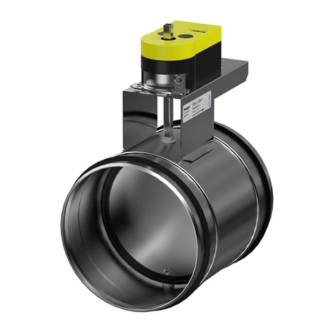
Circular airflow measurement and commissioning damper.
The CRM consists of a duct section with a damper and
measuring device. The connections are fitted with rubber
seal ring.
The damper has a lockable knob for manual adjustment
and indicators for open and closed damper blade position
are stamped in the damper’s exterior surface.
Inside the damper, there is a measurement unit and a
damper blade. The damper blade is available as a solid blade
with rubber gasket (Ductwork leakage class 4), or as a
perforated blade without rubber gasket (Ductwork lea-
kage class 0). Ductwork leakage classification according
to
SS-EN1751 och VVS AMA 98.
When motorised control is selected, the damper knob shelf
is replaced by a larger actuator support shelf. The motorised
control requires an actuating torque according to the dimen-
sions and weights table on page 7. Standard supporting
shelves are 80 mm high to allow possible duct insulation.
Materials and finish
The entire damper is made of galvanized sheet steel.
Adaptation
The damper can be made of other materials, such as
stainless or epoxy-coated sheet steel. Please contact your
nearest sales representative for further information.
Accessories
Actuator:
Sauter ASM115SF901, ASM124SK001, 24 V AC, standard
actuators depending on size.
Other actuators must be ordered, see actuator table page 7.
Wiring diagrams are available in current Installation -
Commissioning - Maintenance Instructions available at the
Swegon web page.
Knob:
CRTT-1 for manual control.
Quick connection:
FSR. Clamp with quick-acting lock.
Planning
CRM is equipped with components for a differential pressure
method of measurement. In order to meet the specified met-
hodic error, a straight duct length must be arranged upstream
of the damper. See "Methodic Errors" and Figure 2.
When planning for actuator-controlled forcing, the min.
permissible air flow indicated in the diagram must be
taken into account. The methodic error (according to
table) is not applicable to the airflows that are less than
the min. permitted flow.
Installation
Damper is Inserted into the connecting duct and fixed in
position by pop rivets or by means of an FSR clamp. See
Figure 1.
Commissioning
Connect hoses from a manometer to the measurement
nipples. Turn and lock the damper blade at the desired
setting angle For particulars of motorised control, we
refer to the actuator supplier’s instructions. K-factors are
shown on the product’s identification label. The K-factor
can also be found in the relevant commissioning instruc-
tions at www.swegon.com.
Maintenance
Clean the damper whenever needed by means of a
vacuum-cleaner or by wiping surfaces with a cloth.
Environment
The Declaration of Construction Materials is available
from www.swegon.com.
Methodic Errors
Type of obstruction
upstream of the CRM
Length of straight duct (L)
upstream of the CRM
For m2= 5% For m2=10%
One 90° bend. 3 x Ød 2 x Ød
Two 90° bends in the same
plane.
4 x Ød 2 x Ød
Two 90° bends in aligment at
right angles to one another.
4 x Ød 2 x Ød
One 45° damper. 6 x Ød 3 x Ød
One T-piece. 4 x Ød 3 x Ød
m2= methodic error. Method for measurement of airflows in
ventilation Installations.
