INSTALLATION GUIDE
ThermShield Standard Installation Method
(Square/Rectangular)
Applies to...
• Actionair ThermShield FD
Health and safety
• This process must be undertaken by competent per-
sons. More than one person may be required to ensure
the safe handling of large dampers and other materi-
als. Use must be made of access equipment to ensure
unsafe practices are not used to approach walls or dif-
cult access areas.
• Standard site PPE should be used (minimum steel toe
cap boots, hard hat); together with any protective
eyewear, gloves and masks, when drilling or cutting is
being undertaken. The latter should also be used when
handing the wall construction materials, as dened by
the material suppliers. If loud equipment is being used,
hearing protection should be used.
• All waste materials should be collected and disposed of
as dened by the relevant supplier.
• Actuators: All wiring should be carried out in accor-
dance with the wiring details provided by the IEE and
BS regulations and by a competent person. Care must
be taken when installing and inspecting dampers, as
they are likely to close without warning due to loss of
electrical power or a temperature rise in the ductwork.
This is their prime function. Do not insert any items,
ngers or limbs between the blades. Larger dampers
must be handled in accordance with current regula-
tions and good practice due to weight.
Contents
Applies to... .......................................... 1
Health and safety .................................. 1
CE Installation Method Overview ..................... 2
Fire damper installation openings..................... 3
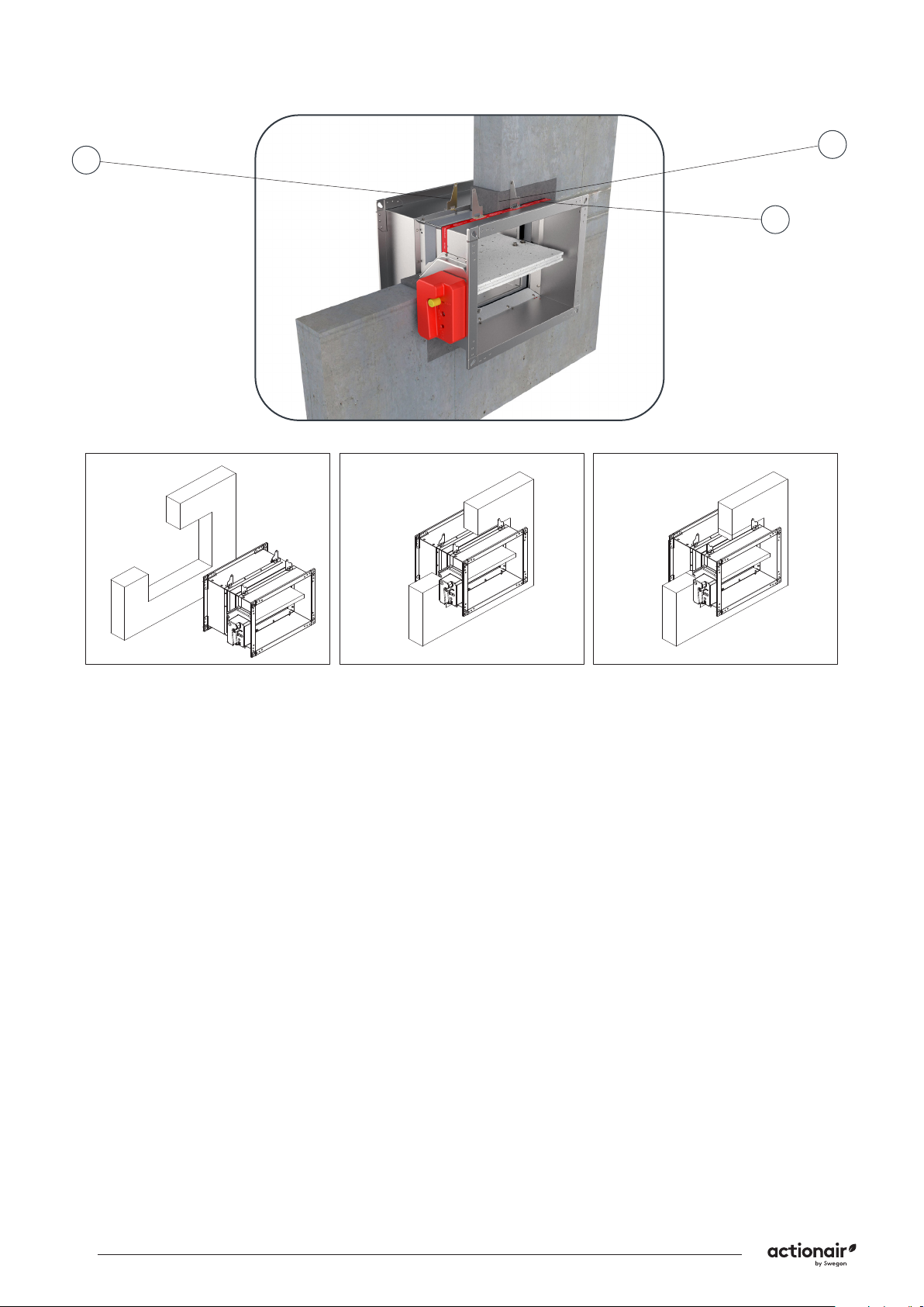
Rigid wall installation (mortar sealing)............. 4
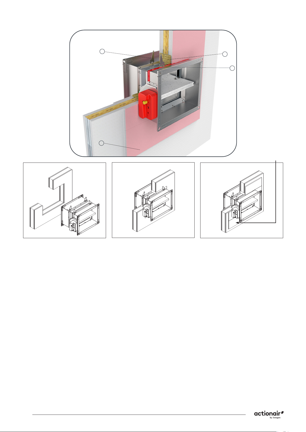
Rigid wall installation (mineral wool sealing) .. 5
Rigid wall installation (Fire Batt) ....................... 6
Flexible wall installation (mortar sealing) ........ 7
Flexible wall installation (mineral wool
sealing) ................................................................ 8
Flexible wall installation (Fire Batt)................... 9
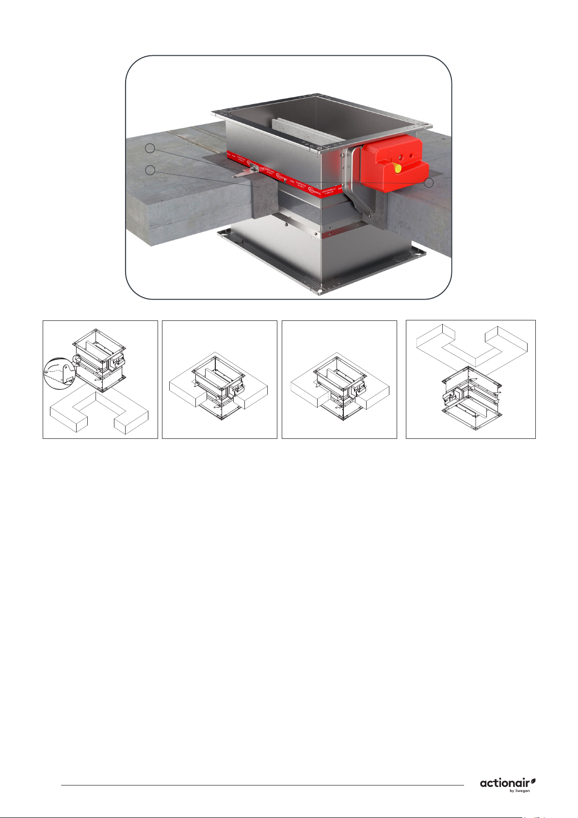
Rigid floor/ceiling installation (mortar
sealing) .............................................................. 10
Rigid floor/ceiling installation (Fire Batt) ....... 11
Suspension for mortarless floor installation .. 12
Suspension for mortarless ceiling installation 13
Suspension for mortarless installation close to
ceiling................................................................. 14
Battery assembly installation 2x2 ................... 15
Battery assembly installation (floor/ceiling)
2x2 ..................................................................... 16
Battery assembly installation 1x2 ................... 17
Minimal seperation damper installation......... 18
Periodic maintenance............................ 20
Actuators............................................21
Wiring Diagrams .................................. 24
Dimensional Data................................. 26
Inspection and handover check sheet........ 28