manuals.online logo
Brands
  1. Home
  2. •
  3. Brands
  4. •
  5. Swegon
  6. •
  7. Fire And Smoke Damper
  8. •
  9. Swegon Actionair A60 User manual

Swegon Actionair A60 User manual

D
IOM
www.actionair.co.uk
[email protected]
A60 Marine
Fire Damper
With ATEX rated
Pneumatic
(Hytork) Actuator
1. Description
The actionair Marine Fire Damper is tested and approved for
fitting to class A-0 A-15 A-30 A-60 divisions (bulkheads and
decks), when suitably insulated.
A-0 does not require any insulation to the casing.
2. Tests, approvals and certification
Lloyds Register Approved.
DNV-GL Approved.
ABS Approved
USCG Approved.
Transport Canada approved.
MED Marine Equipment Directive Compliant.
Fire tested to the latest IMO FTP code & in compliance
international convention for the safety of life at sea (SOLAS)
Sira certification (Ex) category 2 equipment
Corrosion Tested - EN60068-2-52 severity 2 conditions
Vibration Tested – EN60068-2-6 (5Hz to 350Hz @2g)
3. Health and Safety
Care must be taken when installing and inspecting dampers,
as they are likely to close without warning due to loss of
electrical power, or a temperature rise in the ductwork. This is
their prime function.
Do not introduce any items, fingers or limbs between the
blades.
Larger dampers are heavy and must be handled in accordance
with current local regulations and good practice.
All wiring should be carried out in accordance with the wiring
details provided, to the IEC regulations.
4. General Information
The actionair Marine Fire Damper is suitable for both vertical
and horizontal applications, with airflow in either direction.
The dampers tested to IMO fire test procedures Code, Annex 1
Pt 3, are normally open, and fail-safe to the closed position. The
actionair Marine Fire Dampers are supplied with the blades in
the fully interlocked closed position to avoid damage during
transit and installation. It is recommended that the dampers
remain closed until actual date of commissioning. All fire
dampers are life safety products and must be treated with care
during handling, storage and installation.
Actionair Marine Fire Dampers are designed for applications in
normal dry filtered air systems and should be subjected to a
planned inspection programme.
5. Installation - see below.
6. Maintenance & Cleaning
Dampers are supplied in two casing and blade material
options: -
Galvanised Steel casing and 430 Stainless steel blades, only
suitable for installation in dry filtered systems.
316 Stainless steel casing and blades and drive - more suited
for corrosive conditions, but even this will rapidly corrode and
fail if not properly maintained, when used in air intake systems
at sea. The addition of a mist eliminator is highly recommended,
and access must be provided for maintenance.
7. Testing
Two levels of testing exist.
Routine testing - Monthly, or in accordance with maintenance
programme, release and reset damper (via control system or
ETR test switch). Check remote indication or visual check of
mechanical pointer as appropriate.
Visual check at damper - At commissioning and at least once
a year, check damper operation by removing and
re-applying power to actuator. (via ETR test switch).
Visually check blades for damper closed and open positions.
Prove remote indication if applicable.
8. Routine Maintenance
Depending upon environmental conditions, each damper will
merit its own cleaning regime. Particularly hostile areas.
‘Frequency of maintenance’ should be determined by
collecting historical data from previous visits, and for this
reason, commence maintenance programmes.
Dampers in ‘Dry Filtered Air’ require very limited maintenance.
When exposed to fresh air intakes and/or inclement conditions
this may require monthly cleaning and lubrication maintenance
to be performed.
9. Cleaning
Using light lubricant, clean all exposed surfaces, using a cloth.
Remove all traces of surface staining, as this will deteriorate
further causing deeper material corrosion.
For 316 stainless steel blades and case, pay specific attention
to the blade rivets where crevice corrosion will cause rapid
failure of blades if not kept in check.
If damper is stiff to operate lubricate blade ends, open and
close damper successively until the damper moves with ease.
(This may necessitate removal of the actuator and operating
the blades manually by the drive shaft).
Refit actuator and re-test.
Clean off excessive lubricant.
YYYY Denotes
the year the
Wheel mark
is affixed to damper
0038/YYYY
www.actionair.co.uk
[email protected]
10. Damper installation
All installations shall be carried out in accordance with the
relevant Marine/Offshore Authority requirements.
The damper should be installed in accordance with Insulation
details that represent a typical installation.
Please refer to the relevant notified body certificates for
insulation lengths located on Actionair website:
https://www.actionair.co.uk/products/a60-marine-damper
Bolt holes provided as standard on the damper flanges (unless
otherwise stated) at 150mm maximum centres. Matching hole
positions are necessary on mating coaming/duct flanges.
Apply approved fire-resistant sealant/gasket to mating flanges
and position damper.
Bolt A60 square/rectangular dampers using suitable steel bolts
minimum M8 diameter and minimum M6 diameter on A60
circulars.
Important:
For insulation lengths ** please refer to the relevant notified body certificates located on
Actionair website: https://www.actionair.co.uk/products/a60-marine-damper
Multiple Damper Assemblies
Tested and approved to a size of either;
(2x1) 2080mm x 1000mm
or (1x2) 1000mm x 2080mm
Figure 1 Figure 2
Figure 3
Figure 4
www.actionair.co.uk
sales@actionair.co.uk
11 Actuator Installation:
The actuator mounting plate is used also as a transit plate
prior to fitting of the actuator on site. The transit plate keeps
the damper blades closed by retaining the damper drive
shaft in a fixed position. When the plate is removed the drive
shaft is not secured.
Remove the 2No cross-recessed (Pozi) head screws
retaining the transit plate and discard the screws.
Using the 4No socket head cap screws supplied (M8 or M6
for HYTORK or FESTO actuators respectively), fit transit plate
(hereafter referred to as the mounting plate) to the
actuator.
Refit mounting plate to damper casing or bracket,
(whichever is the case) using 4No steel rivets supplied,
ensuring that the 4 holes in the damper casing line up with
the appropriate slots in the mounting plate (Marked ‘X’ on
figure 7, below).
*IMPORTANT* - please ensure damper blades are in the
fully closed position prior to mounting actuators. Failure to
do so may damage drive shafts and render the damper
inoperable.
12. Pneumatic Thermal
Release (PTR):
The PTR assembly is a special purpose design and is
supplied with necessary tubing that connects to the quick
fit couplings of the PTR and actuator. The PTR coupling
must not be disassembled, and the appropriate size tubing
must be connected to ensure correct operation.
13;PTRInstallation:
SelectpositionforPTR,ideallythisshouldbeinthetophalfof
theductandsufficientlyclosetotheactuatortoalloweasy
connectionofthe4mmdiameternylontubesuppliedbyActionair.
Drillholeinselectedpositionusinga30mmdiameterholecutter,
removing/deburrsharpedges.
PositionPTRanddrillthe4No3mmdiameterfixingholes.
RemovePTRandapplyapprovedfire‐retardantsealantonthe
ductaroundthehole.
RefitPTRandsecurewiththe4Nocross‐recessed(Pozi)head
screwsprovided.
Connect4mmdiametertubetotheactuatorandPTR.
Connect6mmdiametertubetoinputsideofPTR
Connectairsupply.Damperopensfully,
Important:Testingmethodoperationmustbeundertaken

14;TestMethod
ThisMUSTbecarriedoutforeachandeveryinstallation.
(Withairsupplyconnected)
Test fail‐safe operation by temporarily removing and refitting the
brassfusiblelink,onthePTR.
Pushspringloadedbottomleverupwards–Linkwillliftoverthe
smallsocketcapheadscrew,onthefusiblelinkbody
Releasebottomlever.AirexhaustsfromthePTR,ensurecomplete
damperclosure.
RefitlinkbypushingthecentralpinatthebottomofthePTR
upwards with a small screwdriver, whilst rotating bottom lever
upwards and refitting brass link over the small socket cap hade
screw
Figure 7
Figure 5
Figure 6
Figure 8
Actuator / transit
Plate, (Label side)
X4 Socket head
cap screws
Actuator
www.actionair.co.uk
[email protected]
Fault Possible problem Recommended action
Damper fails to open or partially
opens.
Insufficient air pressure / leak / blockage. Check correct 5 bar (minimum) air pressure is
present at actuator.
Brass fusible link not fitted Refit link
Brass fusible link has activated. Replace fusible link.
Actuator mounting plate fitted incorrectly Refer to Actuator installation –
Actuator / Transit / Mounting Plate alignment
figure 6
Actuator open ‘End Stop’ adjustment
incorrect.
Refer to Actionair Technical sales office.
Damper fails to fully close when air
pressure is removed.
Damper not correctly synchronised with
the actuator
Remove air supply to actuator.
Remove actuator from damper.
Fully close damper.
Refit actuator in accordance with
Actuator installation –
Actuator / Transit / Mounting Plate alignment
figure, page 3.
Damper fails fully close when Fusible
Link element is removed.
Air supply connections incorrect. Check fittings. (Refer to page 3)
Refer to Actionair Technical sales office.
Actuator closed ‘End Stop’ adjustment
incorrect.
Refer to Actionair Technical sales office.
Swegon Air Management are
ISO9001 & ISO 14001 certified
LNNN00300 – REV 6
Special Conditions of Safe Use
1. The associated spring return failsafe actuator must be suitably rated ATEX
certified for the hazardous atmosphere into which it is to be installed.
2. The equipment must be suitably bonded to a common earth point and
continuity to be checked upon installation.
3. The equipment must not be subjected to charging mechanisms stronger
than manual rubbing.
4. The minimum ignition energy of dust atmospheres into which the equipment
is installed is to be >1mJ

Other Swegon Fire And Smoke Damper manuals

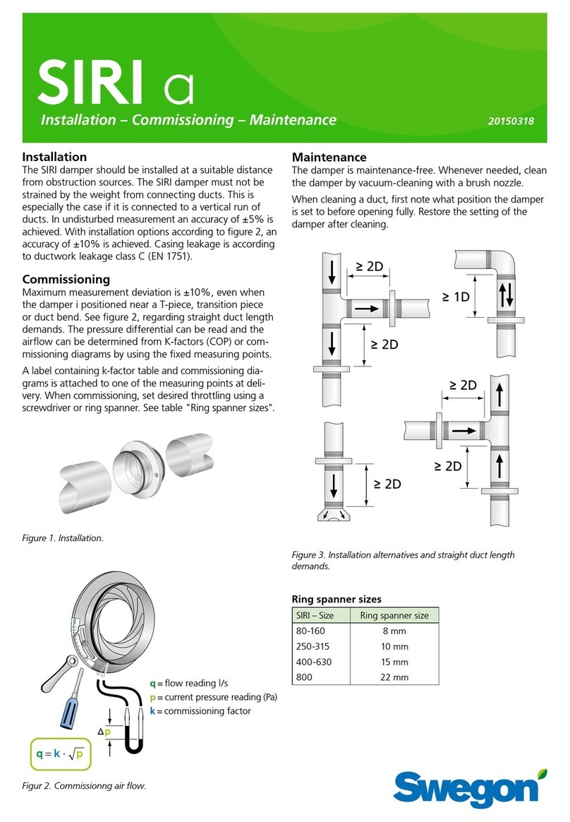
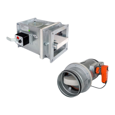
Swegon actionair DWFX-C User manual

Swegon

Swegon actionair DWFX-C User manual

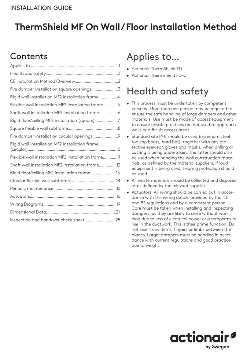
Swegon Actionair ThermShield MF User manual

Swegon

Swegon Actionair ThermShield MF User manual

Swegon Actionair SmokeShield PTC User manual

Swegon

Swegon Actionair SmokeShield PTC User manual

Swegon Actionair ThermShield FD User manual

Swegon

Swegon Actionair ThermShield FD User manual

Swegon actionair FireShield User manual

Swegon

Swegon actionair FireShield User manual

Swegon Actionair CSS Series User manual

Swegon

Swegon Actionair CSS Series User manual

Swegon Actionair A60 User manual

Swegon

Swegon Actionair A60 User manual

Swegon Actionair ThermShield FD User manual

Swegon

Swegon Actionair ThermShield FD User manual

Swegon REACT Pa User manual

Swegon

Swegon REACT Pa User manual

Swegon BLBd Guide

Swegon

Swegon BLBd Guide

Swegon SIRI a Guide

Swegon

Swegon SIRI a Guide

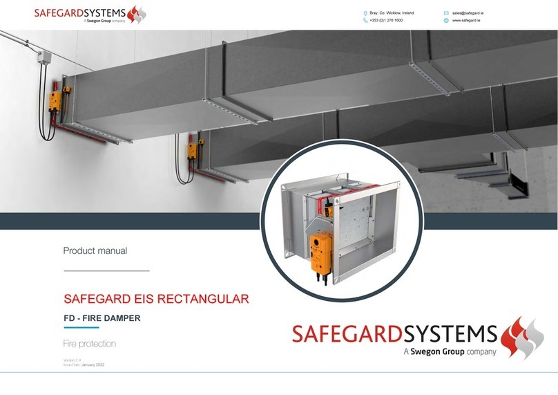
Swegon SAFEGARDSYSTEMS FD 25 User manual

Swegon

Swegon SAFEGARDSYSTEMS FD 25 User manual

Swegon actionair DWFX-F User manual

Swegon

Swegon actionair DWFX-F User manual

Popular Fire And Smoke Damper manuals by other brands

Price FD-RD installation instructions

Price

Price FD-RD installation instructions

Trox Technik FKR-EU Supplementary Operating Manual

Trox Technik

Trox Technik FKR-EU Supplementary Operating Manual

Maico BSB VC Series Installation, Operating and Maintenance Instruction

Maico

Maico BSB VC Series Installation, Operating and Maintenance Instruction

NCA FSD-RD-211 Installation, operation & maintenance instructions

NCA

NCA FSD-RD-211 Installation, operation & maintenance instructions

KOOLAIR FDS-3G Series manual

KOOLAIR

KOOLAIR FDS-3G Series manual

dalap ELIS user manual

dalap

dalap ELIS user manual

Greenheck HSD-401 Installation, operation and maintenance instructions

Greenheck

Greenheck HSD-401 Installation, operation and maintenance instructions

Mandik FDMR installation instructions

Mandik

Mandik FDMR installation instructions

Rf-t KAMOUFLAGE MP Series manual

Rf-t

Rf-t KAMOUFLAGE MP Series manual

Rf-t CU2 manual

Rf-t

Rf-t CU2 manual

pottorff BD-50-SS installation instructions

pottorff

pottorff BD-50-SS installation instructions

Advanced Air 2530 CE Series manual

Advanced Air

Advanced Air 2530 CE Series manual

Lindab FNC1 Installation booklet

Lindab

Lindab FNC1 Installation booklet

LUCOMA DRK Installation, operation and maintenance instructions

LUCOMA

LUCOMA DRK Installation, operation and maintenance instructions

Helios AIR1-JVK Installation and operating instructions

Helios

Helios AIR1-JVK Installation and operating instructions

Rf-t CU2 manual

Rf-t

Rf-t CU2 manual

VPro WT Series instruction manual

VPro

VPro WT Series instruction manual

Zonefirst Fresh Air Cycler FX1 Installation and operating instructions

Zonefirst

Zonefirst Fresh Air Cycler FX1 Installation and operating instructions

manuals.online logo
manuals.online logoBrands
  • About & Mission
  • Contact us
  • Privacy Policy
  • Terms and Conditions

Copyright 2025 Manuals.Online. All Rights Reserved.