Swisher 2646 UNIVERSAL MOUNTING KIT User manual

ATV ACCESSORIES
1602 CORPORATE DRIVE PO BOX 67 WARRENSBURG, MISSOURI 64093
PH 660. 747. 8183 AX 660. 747. 8650
swisherinc.com
MANU ACTURING QUALITY LAWN CARE EQUIPMENT SINCE 1945
Owner’s
Manual
Accessories Mount
2646
Extension Kit
2900
Mount Kit Traxter
7119
Mount Kit Outlander
7668
IMPORTANT
Read and follow all
Safety Precautions
and Instructions
Before Operating this
Equipment.
Made In The
USA
ASSEMBLY
OPERATION
SERVICE AND ADJUSTMENT
REPAIR PARTS
2800
Sold as Separate Pieces!!!!
REV. 05-171

LIMITED WARRANTY
The manufacturer’s warranty to the original consumer purchaser is: This product is free from
defects in materials and workmanship for a period of one (1) year from the date of purchase by
the original consumer purchaser. We will repair or replace, at our discretion, parts found to be
defecti e due to materials or workmanship. This warranty is subject to the following limitations
and exclusions:
1) Commercial Use
The warranty period for any product used for commercial or rental
is limited to ninety (90) days from the date of original purchase.
2) Limitations This warranty applies only to products which ha e been properly
assembled, adjusted, and operated in accordance with the
instructions contained within this manual. This warranty does not
apply to any product of Swisher Mower and Machine Co., Inc.,
that has been subject to alteration, misuse, abuse, improper
assembly or installation, or shipping damage.
3) Exclusions Excluded from this warranty are normal wear, normal
adjustments, and normal maintenance.
In the e ent you ha e a claim under this warranty, you must return the product to an authorized
ser ice dealer. All transportation charges, damage, or loss incurred during transportation of
parts submitted for replacement or repair under this
warranty shall be borne by the purchaser.
Should you ha e any questions concerning this warranty, please contact us toll-free at 1-800-
222-
8183. The model number, serial number, date of purchase, and the name of the authorized
Swisher dealer from whom y
ou purchased the mower will be needed before any warranty claim
can be processed.
THIS WARRANTY DOES NOT APPLY TO ANY INCIDENTAL OR CONSEQUENTIAL
DAMAGES AND ANY IMPLIED WARRANTIES ARE LIMITED TO THE SAME TIME
PERIODS STATED HEREIN FOR ALL EXPRESSED WARRA
NTIES. Some states do not
allow the limitation of consequential damages or limitations on how long an implied warranty
may last, so the abo e limitations or exclusions may not apply to you. This warranty gi es you
specific legal rights and you may ha e other rights, which ary from state-to-
state. This is a
limited warranty as defined by the Magnuson-Moss Act of 1975.
2

SAFETY PRECAUTIONS & DECALS
Read this manual c mpletely. Failure t bserve the f ll wing safety instructi ns
c uld result in seri us injury r death.
This Safety Alert Symb l indicates imp rtant messages in this
manual. When y u see this symb l, carefully read the message that
f ll ws and be alert t the p ssibilitylity f pers nal injury.
Read the manual. Learn to operate this machine safely.
Keep the operating speed LOW!!!!! Do not operate o er 5 MPH (8KMH).
Allow only responsible adults who are familiar with these instructions to operate this machine. Ne er
allow children to operate this machine.
Be sure the area is clear of other people before operating. Children are often attracted to the machine
and the operating acti ity. Never assume that children will remain where y u last saw them. Keep
children under the watchful care of another responsible adult.
Watch for traffic when operating near or crossing roadways.
Do not operate the attachment if it has been dropped or damaged in any manner. Repair as necessary.
Stop and inspect the equipment if you strike an object. Repair if necessary, before restarting.
Dress properly. Do not operate when bare foot or wearing open sandals.
Do not operate the machine while under the influence of alcohol or drugs.
Ne er tamper with safety de ices. Check their proper operation regularly.
Operate attachments up and down slopes. There is a significant risk of o erturns when operating across
slopes.
Never make adjustments r repairs with the ATV engine running.
OD45- Warning Decal
OD55- Danger Decal
3

FIGURE 1
4
ITEM
NO. QTY. PART
NO. DESCRIPTION ITEM
NO. QTY PART
NO. DESCRIPTION
1 1 2630TK Channel Mount 15 1 N -655 3/4 - 10 X 7 1/2 GR 5 olt
2 1 2593TK Slide ar 16 1 N 243 3/4 - 10 X 5 GR 5 olt
3 2 2596TK Leaf Spring 17 1 N -609 3/4 - 10 Nyloc Nut
4 2 2631TK Spring Shackle 18 2 2633TK Mount racket Short
5 2 2596-1 Nylon ushing 19 2 2635TK racket Plate Short
6 1 2638TK ATV racket Left 20 2 2632TK Mount racket Long
7 1 2637TK ATV racket Right 21 2 2634TK racket Plate Long
8 2 2641TK acking racket R&L 22 2 N -281 1/2 - 13 Nyloc Nut
9 8 N -182 3/8 -16 Nyloc Nut 23 4 N -177 1/2 NR Mach ushing
10 2 N -561 5/8 - 11 Nyloc Nut 24 1 9609TK Spacer 1.25 X .75 X 2.1875
11 2 N -699 5/8 - 11 X 3 GR 5 Hex olt 25 1 2655TK Spacer 1.25 X .75 X 1.5
12 4 N -645 3/8 - 16 x 4 GR 5 Hex Head 26 2 N -577 1/2 - 13 X 3 1/2 GR5 olt
13 2 N -247 Hair Pin #10 27 4 N -619 3/8 - 16 X 2 1/2 GR5 olt
14 2 N -244 1/2 X 2 3/4 Clevis Pin 28 8 N -272 3/8 SAE Washer
1
2
3
4
5
6
7
8
9
10
12
13
14
15 or 16
17
18
19
20
21
9
22
23
24
25
26
27
Note:
Accessory
Mount Holes
11
28
28

INSTALLATION OF ACCESSORY MOUNT
TO ENSURE PROPER INSTALLATION, CAREFULLY
FOLLOW ALL INSTRUCTIONS LISTED BELOW
NOTE: The CV guards n y ur ATV maybe need t be trimmed r therwise m dified t all w f r
installati n and pr per clearance f r the Access ry M unt.
• If needed, for clearance, raise the front of the ATV. Make sure the support used is very stable.
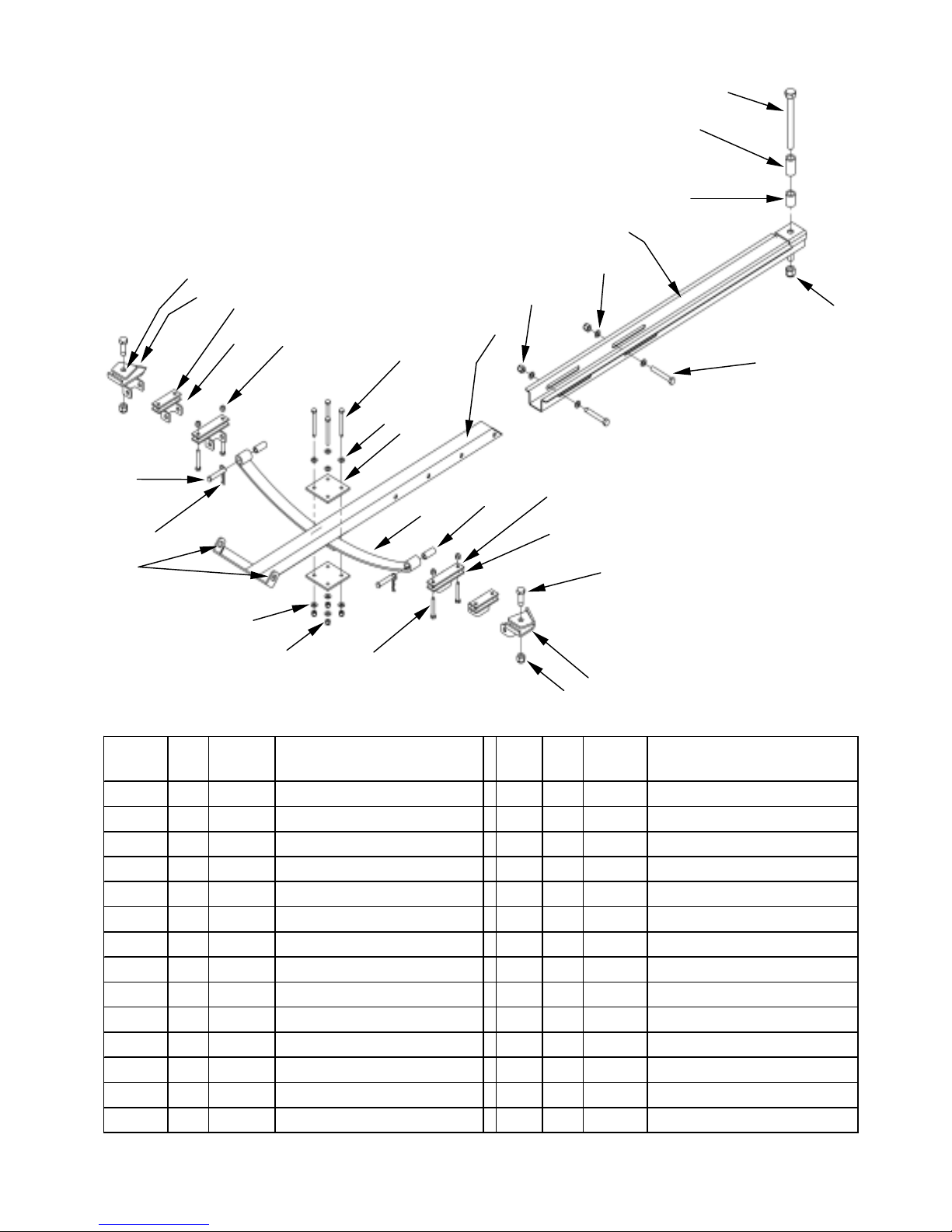
• Lay out the hardware under the ATV, as shown.
• Mount the proper brackets to the lower A-arms of your ATV as near as possible to the outside end. Do not
securely tighten at this time.
4. Mount leaf springs (3) to mounting brackets with cle is pin (14) and hair pin (13).
5. Attach channel mount (1) to the ATV ball hitch mount with 3/4 - 10 bolt (15 OR 16) and 3/4 - 10 nyloc nut
(18). N te: the spacers (24 and 25) need to be installed to keep the accessories mount assembly le el and
for clearance.
6. Using two 1/2 - 13 bolts (26), four 1/2 bushings (23) and two 1/2 - 13 nyloc nuts (22) attach slide bar (2) to
channel mount (1).
7. If pre iously raised, lower the ATV to the ground.
8. Place the two leaf springs (3), from step 4 and the assembly from step 6 between the spring shackles (4).
Secure with four 3/8 – 16 bolts (12), eight washers (28) and four nyloc nuts (9).
9. Adjust the slide bar (2) so the accessory mounting holes are approximately two inches ahead of the front
wheels. The accessory mounting holes should also be approximately 9’ abo e the ground for proper
operation of the optional bucket and blade attachments. Some adjustment may be needed, after
attachment is installed, to assure acceptable clearance between the attachment and the ATV.
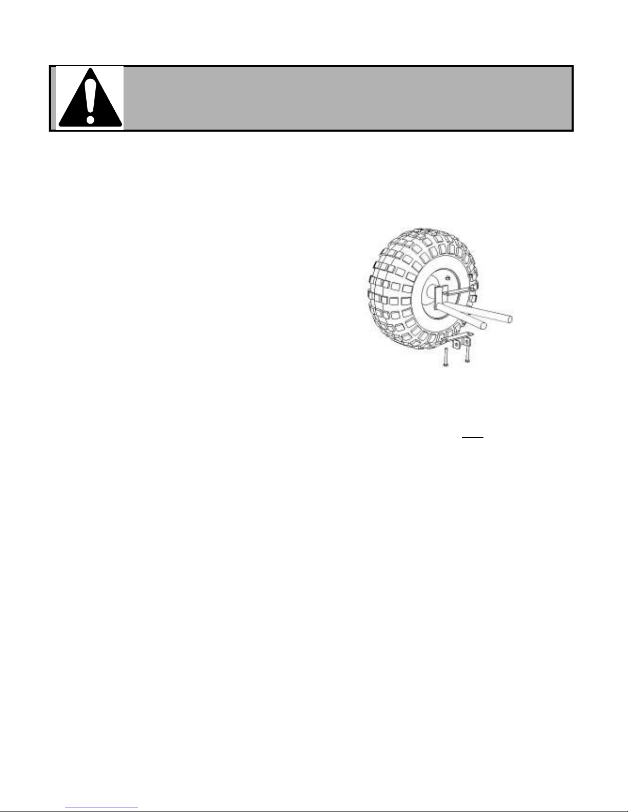
10. Check clearance between the m unting brackets and the ATV wheel rims by turning the ATV
steering t the extreme right and then the extreme left. Adjust l cati n f the brackets if necessary.
Securely tighten all fasteners starting with the f ur b lts listed in step 8.
11. Remo al of the mount assembly: Remo e hair pins (13), pull cle is pins (14) and remo e the channel
mount (1) from the ATV ball hitch. Lea e the mounting brackets attached to the A-Arms.
For ease of remo al of the cle is pins the ATV should be in the same approximate raised or lowered
position as when the bolts listed in steps 8 and 10 were tightened.
MOUNTING BRACKETS
Included with your new ATV accessories mount are three sets of mounting brackets for ATV’s.
Brackets 18,19 and 20,21 are two sets that will work on most ATV’s. The determining factor is what type of
A-arms (lower portion of the front axle) are used on your ATV. If your A-arm is narrow then use bracket set
18, 19. If your A-arm is wide then use bracket set 20,21. If you ha e a Polaris ATV use brackets 6, 7, and 8.
N te: The Polaris brackets are right and left oriented. Make sure you set them up as shown in Fig. 1.
REFER TO FIGURE 1 WHILE INSTALLING THE ACCESSORY MOUNT
5

Installati n Instructi ns
1. Place U-bracket o er rear A-arm bar as shown.
2. Using supplied hardware, assemble plates and brackets.
Position the brackets so they allow wheels to turn without
contacting the rims (Reference step 10 on page 5) . Front
bolt NB619 should be close to the front of the A-arm,
contacting it if possible.
H nda M unting Instructi ns
B mbardier Traxter M unting Instructi ns
Bracket
Notched Plate
(Part # 7120)
Spacer (Part # 7121)
INSTALLATION INSTRUCTIONS
Kit # 7119 Required
Same as ab ve with additi n f spacer and
guard m dificati n
A Arm Guard M dificati n
Guard to be modified by Owner
6
Honda A-arm
U-bracket
#2677TK
Mount Bracket Long
#2632TK
3/8 – 16 bolt
#NB-619
Bracket Plate Long
#2634TK
3/8 – 16 Nyloc Nut
#NB182

MOUNTING INSTRUCTIONS
(REFERENCE FIGURE ABOVE, LEFT SIDE SHOWN)
RAISE ATV SO THERE IS ENOUGH ROOM TO WORK. MAKE SURE THE SUPPORT
USED TO HOLD UP THE ATV IS VERY STABLE. LAY OUT THE PARTS AND HARDWARE UNDER THE ATV.
MOUNT THE BRACKET AND WELDMENT AS SHOWN IN THE FIGURE. REPEAT THE SAME PROCESS FOR THE
RIGHT SIDE.
REMOVE THE EXISTING 5/16 CENTER BOLT FROM THE A-ARM / WHEEL ASSEMBLY. DO NOT REMOVE ANY
OTHER BOLTS FROM THE ASSEMBLY.
COMPLETE THE INSTALLATION OF THE ACCESSORY MOUNT USING THE INSTRUCTIONS ON PAGE 5 OF THIS
MANUAL.
B mbardier Outlander
Access ry M unt Brackets Kit #7668
ACCESSORY MOUNT
WELDMENT
3/8 SAE WASHER
5/16 SAE WASHER
3/8 NYLOC NUT
5/16 NYLOC NUT
ACCESSORY MOUNT
BRACKET
3/8 X 2 ½ BOLT
5/16 X 2 BOLT
HARDWARE AND PARTS
2 - ACCESSORY MOUNT BRACKET 7669TK
2 - ACCESSORY MOUNT WELDMENT 7670TK
- 3/8-16 X 2 ½ BOLT NB619
8 - 3/8 SAE WASHER NB272
- 3/8 - 16 NYLOC NUT NB182
2 - 5/16 - 18 X 2 BOLT NB507
2 - 5/16 -18 NYLOC NUT NB181
- 5/16 SAE WASHER NB275
B mbardier Traxter Max Extensi n Kit
Part # 2900 (Opti nal)
Note:
Extension of 21 – 33 inches at
Six inch increments.
NB577 (2 Needed)
NB177 ( 4 Needed)
NB281 (2 Needed)
2697TK
7

swisherinc.com
MANU ACTURING QUALITY LAWN CARE EQUIPMENT SINCE 1945
WHEN ORDERING PARTS, PLEASE HAVE THE
OLLOWING INORMATION AVAILABLE:
* PRODUCT – ________________
* SERIAL NUMBER - _______________
* MODEL NUMBER - _______________
TYPE - _______________
* PART NUMBER WITH PAINT CODE
* PART DESCRIPTION
TELEPHONE - 1-800-222-8183
AX - 1-660-747-8650
SWISHER MOWER & MACHINE CO. INC.
SWISHER MOWER & MACHINE CO. INC.SWISHER MOWER & MACHINE CO. INC.
SWISHER MOWER & MACHINE CO. INC.
1602 CORPORATE DRIVE
P.O. BOX 67
WARRENSBURG, MO 64093
ATV ACCESSORIES
Owner’s
Manual
IMPORTANT
Read and follow all
Safety Precautions
and Instructions
Before Operating this
Equipment.
Accessories Mount
2646
Extension Kit
2900
Mount Kit Traxter
7119
Mount Kit Outlander
7668
This manual suits for next models
4
Table of contents
Other Swisher Lawn And Garden Equipment manuals

Swisher
Swisher 22430 User manual

Swisher
Swisher LV87537 User manual

Swisher
Swisher GC-07 GARDEN CART User manual

Swisher
Swisher ACR-500, ACR-500S User manual

Swisher
Swisher 12886 User manual

Swisher
Swisher 3279 GRASS CATCHER ATTACHMENT User manual

Swisher
Swisher 2643 DUMP BUCKET User manual

Swisher
Swisher E4-U3005 PowerBroom User manual

Swisher
Swisher DT-40 DE-THATCHER User manual

Swisher
Swisher 2644 PALLET LIFTER User manual