Swissdoor ETS 73 Service manual

0548-990/52e
2017.06
Swing door drive mechanism
ETS 73
Mounting and operating instructions
Original
Com. no. ............................................. Pos. .............................. Construction year ...............
Operator ..............................................................................................................................................
Operating place ........................................................................................................................................

ETS 73
0548-990-51---60e_2017.06.indd 0548-990/52e
Page 2 of 85
Mounting and operating instructions
TABLE OF CONTENTS
1 GENERAL REMARKS .................................................................................................5
1.1 Target group.......................................................................................................5
1.2 Where to keep these instructions ......................................................................5
1.3 Adresses............................................................................................................5
1.4 Auxiliary tools and service performances ..........................................................6
2 SAFETY.......................................................................................................................7
2.1 Appropriate use .................................................................................................7
2.2 Safety notices ....................................................................................................7
2.3 Safety regulations ..............................................................................................7
2.3.1 Principles..............................................................................................7
2.3.2 Service..................................................................................................9
2.3.3 Safety devices ......................................................................................9
2.3.4 Malfunctions .........................................................................................9
2.3.5 Accessories/Spare parts.......................................................................9
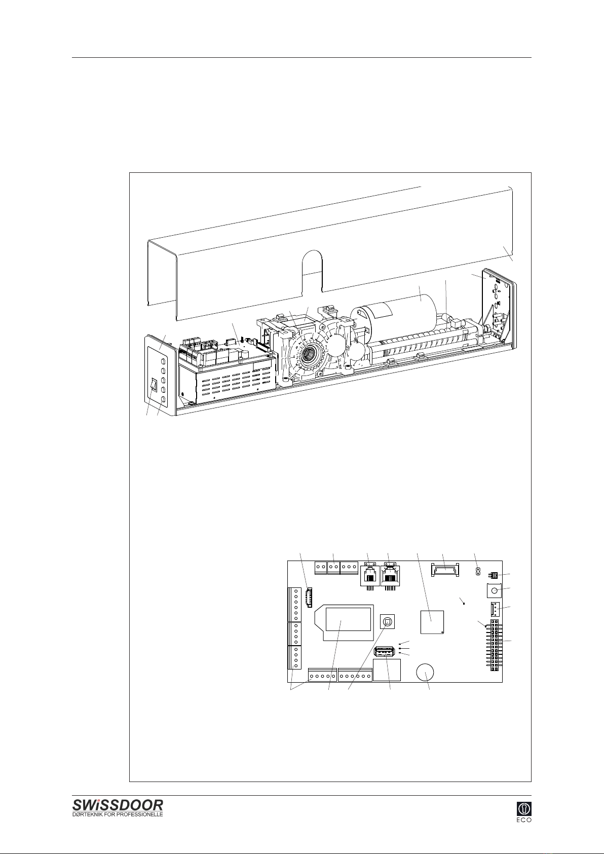
3 PRODUCT DESCRIPTION........................................................................................10
3.1 General remarks ..............................................................................................10
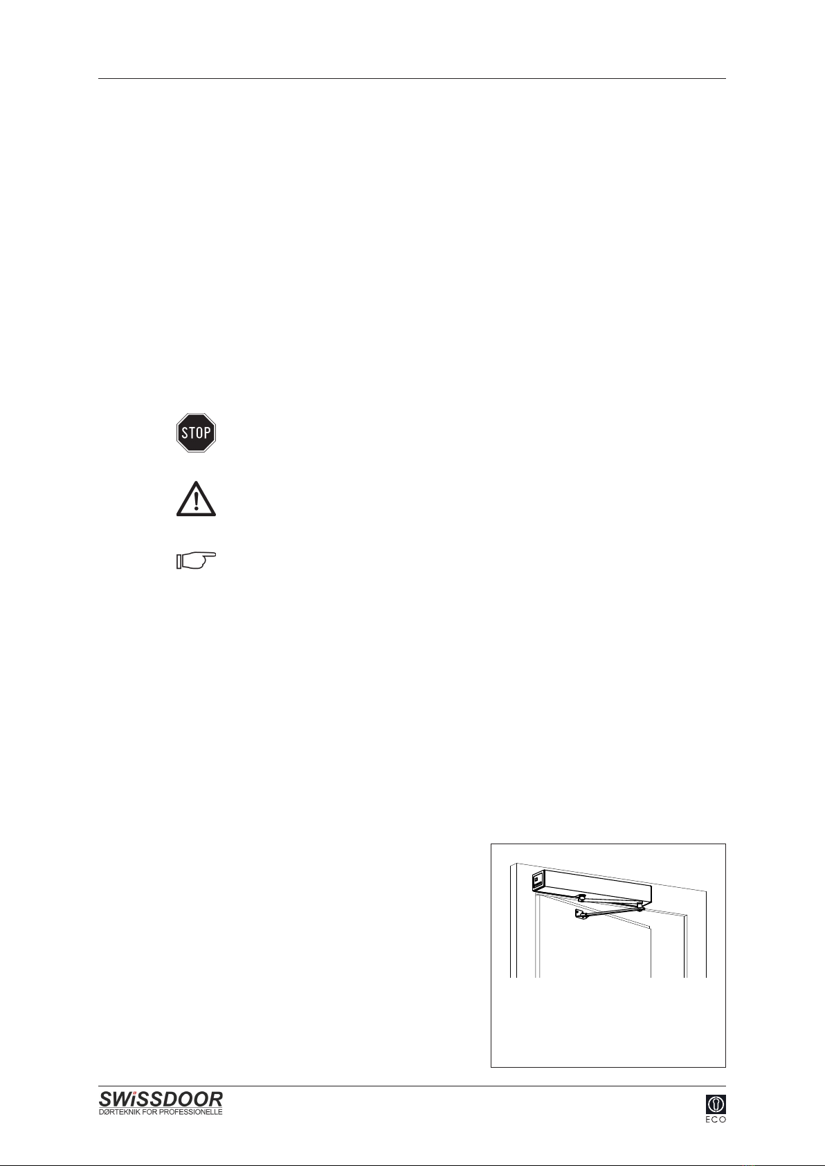
3.2 Standard application ........................................................................................ 11
3.3 Inverse application...........................................................................................12
3.4 Automatic closing sequence control ................................................................12
3.5 Rating plate......................................................................................................13
3.6 Technical data..................................................................................................13
3.7 Application limits without safety elements
according to EN 16005 ....................................................................................14
3.8 Maximum wind-load capacity...........................................................................15
4 MOUNTING ...............................................................................................................17
4.1 Preparation ......................................................................................................17
4.2 Mounting versions............................................................................................18
4.3 General............................................................................................................19
4.4 Normal rods pushing function / Lintel mounting...............................................20
4.5 Sliding rods pulling function / Lintel mounting..................................................23
4.6 Sliding rods pushing function / Lintel mounting ...............................................26
4.7 Sliding rods pushing function / Leaf mounting .................................................29
4.8 Adjusting the pre-stressing of the closing spring .............................................32
4.9 Setting the accelerating function (forceful closing) ..........................................34
4.9.1 Accelerating force...............................................................................34
4.9.2 Forceful closing range ........................................................................35
5 ELECTRICAL CONNECTIONS .................................................................................36
5.1 Power supply ...................................................................................................36
5.2 Cable layout.....................................................................................................38
5.2.1 Lintel mounting ...................................................................................38
5.2.2 Leaf mounting.....................................................................................38
5.2.3 Strain relief .........................................................................................39
5.3 External elements ............................................................................................39
5.4 Motorized lock..................................................................................................40
5.4.1 Motorised lock with direct connection to motor coil ............................40
5.4.2 Motorized lock with own evaluation control ........................................41
5.4.3 Motorized lock with separate evaluation control/power pack .............42

ETS 73
0548-990-51---60e_2017.06.indd 0548-990/52e
Page 3 of 85
Mounting and operating instructions
6 COMMISSIONING.....................................................................................................43
6.1 Inverse application...........................................................................................45
6.2 Closing sequence control ................................................................................46
6.3 Interlock operation ...........................................................................................49
6.4 Adhesive labels................................................................................................50
6.4.1 Service sticker ....................................................................................50
6.4.2 Diagram sticker...................................................................................50
6.5 Mount the drive unit covering...........................................................................51
7 CONTROL..................................................................................................................52
7.1 Main switch ......................................................................................................52
7.2 Program selector .............................................................................................52
7.3 Operating modes .............................................................................................53
7.4 Adjustings ........................................................................................................54
7.4.1 Motional parameters (PARAMETER) .................................................54
7.4.2 Conguration(CONFIG).....................................................................55
7.4.3 Installations with multiple door leaves (DOUBLE DOOR) ..................56
7.4.4 Menu navigation .................................................................................57
8 SERVICE ...................................................................................................................61
8.1 Service for pedestrian doors............................................................................62
8.2 Fundamental checking.....................................................................................63
9 TROUBLESHOOTING...............................................................................................64
9.1 Malfunction with error-no. ................................................................................64
9.1.1 Drive mechanism................................................................................64
9.1.2 Operating............................................................................................65
9.1.3 Safety elements..................................................................................65
9.1.4 Feeding...............................................................................................65
9.1.5 System................................................................................................66
9.1.6 Options ...............................................................................................66
9.1.7 Closing sequence / Interlock function.................................................66
9.2 Malfunction without error-no. ...........................................................................67
9.3 Software update via USB.................................................................................68
9.3.1 Preparation.........................................................................................68
9.3.2 Procedure...........................................................................................69
9.3.3. LED display on the control..................................................................69
9.3.4 Possible errors....................................................................................69

ETS 73
0548-990-51---60e_2017.06.indd 0548-990/52e
Page 4 of 85
Mounting and operating instructions
10 SHUT-DOWN.............................................................................................................70
11 DISPOSAL OF THE INSTALLATION.........................................................................71
12 SPARE PARTS ..........................................................................................................72
13 OPTIONS...................................................................................................................73
13.1 D-BEDIX ..........................................................................................................73
13.1.1 Keys....................................................................................................73
13.1.2 Symbols..............................................................................................73
13.1.3 Operating modes................................................................................74
13.1.4 Display of the door position ................................................................74
13.1.5 Menu level ..........................................................................................75
13.1.6 Setting examples................................................................................76
13.1.7 Error display .......................................................................................77
13.2 KOMBI-D-BEDIX .............................................................................................78
13.3 Open position stop piece integrated in the drive unit.......................................79
13.4 Connection plate for wooden door leaf (normal rods).........................................79
13.5 Mounting plate .................................................................................................80
13.6 Mounting plate ETS 73 Mod ............................................................................80
13.7 Continuous covering ........................................................................................81
13.8 Optional PCBs .................................................................................................82
13.8.1 Relay PCB..........................................................................................82
13.8.2 Radio PCB..........................................................................................83
13.9 LZR-FLATSCAN ..............................................................................................84
14 APPENDIX.................................................................................................................85
Wiring diagram................................................................................ E4-0141-713_ECO
Wiring diagram Relay PCB ............................................................. E4-0141-715_ECO
Wiring diagram motorised locks...................................................... E4-0142-180_ECO

ETS 73
0548-990-51---60e_2017.06.indd
!
0548-990/52e
Page 5 of 85
Mounting and operating instructions
1 GENERAL REMARKS
The present instructions contains all instructions for mounting, commissioning, operation,
service (maintenance/checking) as well as troubleshooting. It is the basis guaranteeing
a faultless and safe operation of the installation and must be completely read and under-
stood before starting the work.
The following basic documents are associated with this installation:
• Mounting and operating instructions 0548-990/52 onto the installation
• Operator manual 0548-991/42 by the operator
• Control booklet 0548-991/52 onto the installation
1.1 Target group
All the work described in the present instructions must only be carried out by experts!
Experts are persons who, based on their professional training and experience, have suf-
cientknowledgeintheeldofpoweredwindows,doorsandgates.Theyaresufciently
familiar with the relevant federal regulations for work protection and accident prevention,
withtheguidelinesandgenerallyrecognizedrulesapplicableforthiseldoftechnolo-
gy which enables them to evaluate if powered windows, doors and gates can be safely
operated.
Only the trained experts of the manufacturer or the supplier are counted among these
persons.
1.2 Where to keep these instructions
The present instructions have to be kept close to the installation, together with the control
booklet!
1.3 Adresses
Distribution agent/
After-sales service
Distribution ECO Schulte GmbH & Co. KG
Iserlohner Landstrasse 89
D-58706 Menden
Tel. +49 23 73 / 92 76-0
Fax +49 23 73 / 92 76-40
www.eco-schulte.de

ETS 73
0548-990-51---60e_2017.06.indd 0548-990/52e
Page 6 of 85
Mounting and operating instructions
1.4 Auxiliary tools and service performances
The auxiliary tools and service performances listed hereafter are available, depending on
the respective situation and authorization (please ask your distribution agent):
• Company portrait
• Homepage
• News
• Info-News via E-mail
• Product brochures
• Product presentation (PowerPoint)
• Submission texts
• Reference list
• Test/homologationcerticates
• CAD data
• Application sheets
• Plans of installations and cutouts
• Training courses
• Spare parts
• Maintenance contracts
• Around-the-clock service (not available in all the countries)

ETS 73
0548-990-51---60e_2017.06.indd
HSKNSK GSK
0548-990/52e
Page 7 of 85
Mounting and operating instructions
2 SAFETY
2.1 Appropriate use
The swing door drive mechanism ETS 73 has been exclusively designed for operating
swing doors. Any other use beyond these application limits is deemed inappropriate and
inadmissible! In the event of an inappropriate use of this system, the safety of the user
may be jeopardized and/or the installation be damaged. The manufacturer declines all
responsibility for these injuries/damages!
2.2 Safety notices
The present instructions uses the following symbols and notes in order to point out certain
residual dangers:
Warning:
Involving danger to life and limb.
Attention:
A situation where material could be damaged or the function impaired.
Note:
Hints which facilitate the work.
2.3 Safety regulations
2.3.1 Principles
• According to standard EN 16005/DIN 18650 describing the safety-related requirements
for automatic door systems, a risk evaluation is to be carried out (in consideration of
the groups of door users and the local situation). This is the basis for the choice of the
different protecting measures. The risk evaluation has to be carried out already during
the planning stage to guarantee that the automatic door system can be safely installed
and operated.
• Whenconguringtheinstallation,itisessen-
tial to make sure that the locally applicable
regulations with regard to the closing edges
are complied with, in order to avoid crushing
and shearing points. It is particularly impor-
tant to make sure that the door leaves do not
have any sharp edges. The secondary closing
edges must be designed by customers in
such a fashion as to eliminate any dangerous
crushing and shearing points.
NSK Secondary closing edge
HSK Main closing edge
GSK Opposing closing edge

ETS 73
0548-990-51---60e_2017.06.indd 0548-990/52e
Page 8 of 85
Mounting and operating instructions
• In order not to create any dangerous squeezing and shearing points, no structural mo-
dicationmustbemadewithinthedoorsurroundings,withoutpriorauthorizationfrom
ECO Schulte GmbH & Co. KG. Furthermore, it is important that no objects (such as
furniture, pallets, etc.) be placed in the vicinity of the door.
• Thedoorleavesandtheirllingsmustbemanufacturedaccordingtotheapplicable
standards(e.g.EN16005).Forthedoorleafllings,brake-proofmaterialrespectively
safety glass shall be used. Transparents door leaves (or their surfaces) must be clearly
recognizable, e.g. by means of a permanent marking or dyed materials.
• The application limits must be observed.
• The choice of fastening elements depends on the construction base.
• Doorsillsorotherprotrudingelementsofthedoorsystemaretobeidentiedbywar-
ning stickers or another appropriate marking means.
• Initsassembledstate,theinstallationmustanswerallthesafetyrequirementsspecied
by the machinery directive.
• The swing door drive mechanism ETS 73 may only be installed and operated in dry
rooms.Ifthisconditioncannotbefullled,thecustomermustprovidesufcientprotec-
tion from moisture.
• The swing door drive mechanism ETS 73 must not be mounted within locations pre-
sentingexplosionhazards.Thepresenceofammablegasesorsmokerepresentsa
considerable safety hazard.
• Allfurtherinterventionsonandmodicationsoftheinstallationthatarenotdescribedin
the present instructions are forbidden!
• Wrapping materials (such as plastic foil, polystyrene foam, strings, ....) represent a
source of danger for children and must therefore be kept out of reach of the latter.
• The installation has been calculated, designed and manufactured on the basis of the
latest state-of-the-art technology and the generally recognized safety-relevant rules and
regulations. It may only be operated if it is in perfect condition, taking into account the
specicationsofthepresentinstructions.Anyusebeyondthedenedapplicationlimits
is inadmissible!
• The installation is to be operated and maintained in such condition that the safety is
guaranteed at all times. An integral part of this condition is the appropriate use, the
compliance with the operating conditions prescribed by the manufacturer, as well as the
regular service (maintenance/checking).
• Theinstallation’sconformitywiththemachinerydirectivemustbeconrmed.

ETS 73
0548-990-51---60e_2017.06.indd 0548-990/52e
Page 9 of 85
Mounting and operating instructions
2.3.2 Service
In order to guarantee the safety of the users at all times, the installation must be checked
withregardtoitssafeconditionbeforetherstcommissioningandduringnormaloperati-
on, at least once a year, by a expert.Thecorrectmaintenance/checkingmustbeconr-
med by entering the date and signature into the control booklet.
2.3.3 Safety devices
It is inadmissible to bypass, shunt or disable the safety devices. Any defective safety devi-
ces may not be disconnected in order to be able to continue the operation of the installa-
tion.
2.3.4 Malfunctions
If any malfunctions occur which might be detrimental to the safety of the users, the instal-
lation must be immediately taken out of operation. It may only be taken back into operati-
on after the malfunction has been repaired and all danger eliminated.
2.3.5 Accessories/Spare parts
A safe and reliable function of the installation can only be guaranteed if it is operated with
the original ECO Schulte GmbH & Co. KG accessories/spare parts. ECO Schulte GmbH
&Co.KGdeclinesallresponsibilityfordamagesresultingfromunauthorizedmodicati-
ons of the installation or from the use of foreign accessories/spare parts.

ETS 73
0548-990-51---60e_2017.06.indd
A
B
C
D
E
G
F
H I
B
J K L M N O P
Q
R
S
T
UVWX
5 V
30 V
SOK
OE
SE
K
X101
X103
X105
X109
X113
X115
X116
X117
X107
X110 X108
X118
X112 X104 X102
X114
X106
0548-990/52e
Page 10 of 85
Mounting and operating instructions
3 PRODUCT DESCRIPTION
3.1 General remarks
The swing door drive mechanism ETS 73 opens and closes the door leaf via a rod as-
sembly (is not shown in the illustration).
Drive mechanism
A Drive mechanism covering
B Side cover
C Spring unit for spring-powered closing respectively opening
D Direct current motor
E Gear
F Output shaft with eight-pointed star for the connection of the rod assembly
G Control
H Main switch
I Program selector keys
Control PCB
J Connection program selector
K Connection terminals
L Serial interface
M CAN
N Processor
O Options connection
P Fire protection (option)
Q Connection of the reference switch
R Potentiometer for slam cushioning
S Rotary shaft encoder
T Connector for power supply unit
U Buzzer
V USB
W Joystick
X LC-Display
LED
5 V green = i.O.
30 V green = i.O.
SOK System greenashing=i.O.
OE Opening element blue = activ
SE Safety element yellow = activ
Control PCB

ETS 73
0548-990-51---60e_2017.06.indd
AB
C
D
E
F
G
AB
0548-990/52e
Page 11 of 85
Mounting and operating instructions
Normal rods
Sliding rods
A Clamping piece
B Rotating arm
C Joint
D Rod arms
E Door connection angle
F Glider
G Sliding rail
3.2 Standard application
During normal operation, the opening and closing movements of the door leaf are moto-
rized. The automatically opening is performed via opening elements. The automatically
closing starts as soon as the programmed hold-open time has expired.
Function in the event of a mains failure
The door leaf is closed from any position by means of spring power. The motor attenuati-
on ensures a controlled closing.

ETS 73
0548-990-51---60e_2017.06.indd 0548-990/52e
Page 12 of 85
Mounting and operating instructions
3.3 Inverse application
The swing door drive unit ETS 73 is also appropriate for inversed operation. This parti-
cular function can be separately programmed for each drive unit. In the event of a power
failure, the inverse application ensures that the door leaf is reliably opened.
During normal operation, the opening and closing movements of the door leaf are moto-
rized. The automatically opening is performed via opening elements. The automatically
closing starts as soon as the programmed hold-open time has expired.
Function in the event of a mains failure or emergency open
The door leaf is opened from any position by means of spring power (unless it has not
been locked). The motor attenuation ensures a controlled opening. An emergency power
supply system is therefore not necessary.
3.4 Automatic closing sequence control
For bi-parting installations, two separate ETS 73 swing door drive mechanisms are used,
which are connected via the CAN bus system.
Drive mechanism 2
Slave
Drive mechanism 1
Master
Earlier door leaf
therstonetoopen
the second one to close Delayed door leaf
the second one to open
therstonetoclose

ETS 73
0548-990-51---60e_2017.06.indd 0548-990/52e
Page 13 of 85
Mounting and operating instructions
3.5 Rating plate
The rating plate (including TÜV and EC
identication)canbefoundonthedirectcur-
rent motor (below the drive unit covering).
3.6 Technical data
Drive mechanism Standard
Power transmission Normal rods
Sliding rods
Dimensions drive mechanism Height 95 mm
Width 690 mm
Depth 120 mm
Weight drive mechanism 10,5 kg
Ambient temperature -15...+50 °C
May only be used in dry rooms max. relative humidity 85 %
Protection type IP 40 (IP 42*)
Operating voltage 230 VAC (+10/-15 %), 50 Hz, 10/13 A
Power consumption drive mechanism max. 560 W
Motor power rating 100 W
Power supply external comsumer 24 VDC (±10 %), 2 A
Torque output shaft max. 80 Nm
Distance door hinge - Output shaft mounting against lintel 280 mm
leaf mounting 380 mm
Lintel depth normal rods max. 250 mm
sliding rods +150/-30 mm
Door opening angle max. 105°
Weight of door leaf max. 250 kg
Width of door leaf EN 3...7 (851...1'600 mm)
see chapter "Application limits"
Opening speed max. 40°/s
Closing speed max. 40°/s
Range of the accelerating function (foreceful
closing) (without mains power) 5...15° stepless adjustable (mechanical)
Motor damping (without mains power) within the range of the
accelerationg function (forceful closing) stepless adjustable (adjusting trimmer)
Hold-open time 0...60 s
Hold-open time Night 0...180 s
Rating plate
* For obtaining
the protection
type IP 42, the
drive mechanism
covering must
be sealed all
around!
Sealing compound
e.g. 6450-105
Adhesive tape
transparent

ETS 73
0548-990-51---60e_2017.06.indd
0...50
kg
51...90
kg
91...130
kg
131...170
kg
171...210
kg
211...250
kg
EN 3 851...950 mm
EN 4 951...1'100 mm
EN 5 1'101...1'250 mm
EN 6 1'251...1'400 mm
EN 7 1'401...1'600 mm
6
5
5
5
2
5
4
5
4
2
3
4
4
3
2
2
3
3
3
2
2
3
3
3
1
1
2
2
2
1
0...50
kg
51...90
kg
91...130
kg
131...170
kg
171...210
kg
211...250
kg
EN 3 851...950 mm
EN 4 951...1'100 mm
EN 5 1'101...1'250 mm
EN 6 1'251...1'400 mm
EN 7 1'401...1'600 mm
4
4
3
3
2
4
2
3
3
2
3
2
2
3
2
1
1
1
1
1
1
1
1
1
1
-
1
1
1
-
0...50
kg
51...90
kg
91...130
kg
131...170
kg
171...210
kg
211...250
kg
EN 3 851...950 mm
EN 4 951...1'100 mm
EN 5 1'101...1'250 mm
EN 6 1'251...1'400 mm
EN 7 1'401...1'600 mm
5
4
4
3
3
4
3
3
3
2
4
3
2
2
2
2
2
1
1
1
1
1
1
1
1
1
1
1
-
-
0...50
kg
51...90
kg
91...130
kg
131...170
kg
171...210
kg
211...250
kg
EN 3 851...950 mm
EN 4 951...1'100 mm
EN 5 1'101...1'250 mm
EN 6 1'251...1'400 mm
EN 7 1'401...1'600 mm
4
4
3
2
2
3
3
2
2
1
2
1
1
1
1
2
1
1
1
1
1
1
1
-
-
1
-
-
-
-
0548-990/52e
Page 14 of 85
Mounting and operating instructions
3.7 Application limits without safety elements
according to EN 16005
Warning:
In the event of swing doors installed in a non publicly accessible areas, without
installation of safety elements that monitor the door leaf movement, the setting
valuesspeciedhereafterfortheopening speed Vo and the closing speed Vc
must not be exceeded.
Leaf weight
Leaf width
Normal rods pushing function (lintel mounting)
Leaf weight
Leaf width
Sliding rods pushing function (lintel mounting)
Leaf weight
Leaf width
Sliding rods pulling function (lintel mounting)
Leaf weight
Leaf width
Sliding rods pushing function (leaf mounting)

ETS 73
0548-990-51---60e_2017.06.indd
2000
2100
2200
2300
2400
2500
2600
2700
2800
2900
3000
800 900 1000 1100 1200 1300 1400 1500 1600
60 km/h
(180Pa)
55 km/h (150 Pa)
50 km/h (125 Pa)
45 km/h (100 Pa)
40 km/h (80 Pa)
35 km/h (60 Pa)
30 km/h (45 Pa)
2000
2100
2200
2300
2400
2500
2600
2700
2800
2900
3000
800 900 1000 1100 1200 1300 1400 1500 1600
65km/h (210 Pa)
60 km/h (180 Pa)
55 km/h (150 Pa)
50 km/h (125 Pa)
45 km/h (100 Pa)
40 km/h (80 Pa)
35 km/h (60 Pa)
2000
2100
2200
2300
2400
2500
2600
2700
2800
2900
3000
800 900 1000 1100 1200 1300 1400 1500 1600
80 km/h (320 Pa)
70 km/h (245 Pa)
60 km/h (180 Pa)
50 km/h (125 Pa)
45 km/h (100 Pa)
40 km/h (80 Pa)
0548-990/52e
Page 15 of 85
Mounting and operating instructions
Clearance width in mm
Clearance height in mm
3.8 Maximum wind-load capacity
Normal rods pushing function (lintel mounting)
Sliding rods pushing function (lintel mounting)
Sliding rods pulling function (lintel mounting)
Clearance width in mm
Clearance height in mm
Clearance width in mm
Clearance height in mm

ETS 73
0548-990-51---60e_2017.06.indd
2000
2100
2200
2300
2400
2500
2600
2700
2800
2900
3000
800 900 1000 1100 1200 1300 1400 1500 1600
55 km/h
(150 Pa)
50 km/h (125 Pa)
45 km/h (100 Pa)
40 km/h (80 Pa)
35 km/h (60 Pa)
30 km/h (45 Pa)
25 km/h (30 Pa)
0548-990/52e
Page 16 of 85
Mounting and operating instructions
Clearance width in mm
Clearance height in mm
Sliding rods pushing function (leaf mounting)

ETS 73
0548-990-51---60e_2017.06.indd
A
BC
D
Y
X
0548-990/52e
Page 17 of 85
Mounting and operating instructions
4 MOUNTING
4.1 Preparation
Attention:
Standard application
It is recommended that a door leaf stop piece be mounted by the customer.
Inverse application
It is imperative for the customer to install a door leaf stop piece!
This stop piece prevents the door leaf from being damaged in the manual ope-
rating mode. As an option, an open position stop piece can be integrated into
the drive unit itself.
1. Check the free running movement of the door leaf.
Should it fail to move smoothly and silently, or if it is out of balance (i. e. it opens or
closesbyitself),theseproblemsmustbeeliminatedrst!
Attention:
The motor connector plug must be re-connected in the control unit, according
to the respective mounting version (Y = standard see chapter 4.2 Mounting
versions). This in order to ensure the cushioning function.
2. Loosen the two screws (A).
3. Pull the control (B) out from under the
gearbox housing (C).
4. Re-connect the motor connector
plug (D).
5. Remount the control unit (B).
standard

ETS 73
0548-990-51---60e_2017.06.indd 0548-990/52e
Page 18 of 85
Mounting and operating instructions
4.2 Mounting versions
DIN left DIN right
Normal rods 0548-104 pushing function
0548-104/01 KTL push. funct.
Lintel mounting see chapter 4.4
Lintel depth 0...250 mm
Drive mechanism 0548-030 alu / 0548-031 inox
Motor connector plug Standard Y, Inverse X
see chapter 4.1
Normal rods 0548-104 pushing function
0548-104/01 KTL push. funct.
Lintel mounting see chapter 4.4
Lintel depth 0...250 mm
Drive mechanism 0548-030 alu / 0548-031 inox
Motor connector plug Standard Y, Inverse X
see chapter 4.1
Sliding rods 0548-134 (620 mm)
pulling 0548-105/02 (830 mm)
Lintel mounting see chapter 4.5
Lintel depth -30/+80 mm (+200 mm)
Drive mechanism 0548-030 alu / 0548-031 inox
Motor connector plug Standard X, Inverse Y
see chapter 4.1
Sliding rods 0548-134 (620 mm)
pushing 0548-105/02 (830 mm)
Lintel mounting see chapter 4.6
Lintel depth -30/+70 mm (+200 mm)
Drive mechanism 0548-030 alu / 0548-031 inox
Motor connector plug Standard Y, Inverse X
see chapter 4.1
Sliding rods 0548-134 (620 mm)
pushing 0548-105/02 (830 mm)
Lintel mounting see chapter 4.6
Lintel depth -30/+70 mm (+200 mm)
Drive mechanism 0548-030 alu / 0548-031 inox
Motor connector plug Standard Y, Inverse X
see chapter 4.1
Sliding rods 0548-134 (620 mm)
pulling 0548-105/02 (830 mm)
Lintel mounting see chapter 4.5
Lintel depth -30/+80 mm (+200 mm)
Drive mechanism 0548-030 alu / 0548-031 inox
Motor connector plug Standard X, Inverse Y
see chapter 4.1
Sliding rods 0548-105/02 pushing function
incl. sliding rail 830 mm
Leaf mounting see chapter 4.7
Lintel depth -30/+200 mm
Drive mechanism 0548-030 alu / 0548-031 inox
Motor connector plug Standard Y, Inverse X
see chapter 4.1
Sliding rods 0548-105/02 pushing function
incl. sliding rail 830 mm
Leaf mounting see chapter 4.7
Lintel depth -30/+200 mm
Drive mechanism 0548-030 alu / 0548-031 inox
Motor connector plug Standard Y, Inverse X
see chapter 4.1

ETS 73
0548-990-51---60e_2017.06.indd
A A A
A A A
0548-990/52e
Page 19 of 85
Mounting and operating instructions
4.3 General
Warning:
Thefasteningbasesmustprovidesufcientsolidity.Ifnecessarytheyhaveto
be reinforced by the appropriate means.
Attention:
The maximum admissible undulation of the fastening base is 1 mm. The drive
unitmustbefastenedwithouttorsionandperpendicularly,usingallthesixxing
holes!
Warning:
TightenallthesixM6xingscrews(A)withatorqueof10Nm!
Note:
Depending on the assembly situation of the drive unit, it may be advisable to in-
stall the program selector on the opposite side (in order to guarantee an optimal
operating facility). Should this be required, the work must be carried out accor-
ding to chapter "Electrical connections".
Note:
In cases where it is planned to integrate an open position stop piece into the
drive unit (option), this stop piece must be mounted prior to the rod assembly
(see instructions for option).
Note:
In case FLATSCANs are planned, they must be mounted according to chapter
13.9.

ETS 73
0548-990-51---60e_2017.06.indd
217
424
650
358 45
76
17*
53**
689
60
0...250 ~398
280 100
60
120
45
9575
170
M6
24
2326
Ø20
z
0548-990/52e
Page 20 of 85
Mounting and operating instructions
4.4 Normal rods pushing function / Lintel mounting
Material:
1 Drive mechanism 0548-030 Covering aluminium
Drive mechanism 0548-031 Covering inox
incl.xingset 0548-107
1 Normal rods 0548-104
Normal rods KTL 0548-104/01
Procedure:
1. Mark out and drill the fastening holes on the lintel and the door leaf.
DIN right = as shown
DIN left = mirror-inverted
Fixing holes
Chassisprole
Lintel depth
Lower edge door frame
Clamping piece
standard
Options * **
0548-114 Clamping piece standard 10...22 53
0548-124 Clamping piece -13 mm 10...12 40
0548-125 Clamping piece +20 mm 10...42 73
0548-126 Clamping piece +50 mm 10...72 103
adjust the dimensions accordingly
Axis of rotation
Table of contents
Popular Door Opening System manuals by other brands

Elvox
Elvox Sound system GIOTTO operating instructions

Johnson Controls
Johnson Controls MC-302E PG+ installation guide

Assa Abloy
Assa Abloy Corbin Russwin DC3200 Series installation instructions

Assa Abloy
Assa Abloy NORTON RIXSON 1600 Series installation instructions

ENFORCER
ENFORCER SD-961A-36GQ installation manual

JCM Technologies
JCM Technologies KEEROLL user manual

Woelm
Woelm HELM GT-L 80 installation instructions

Assa Abloy
Assa Abloy Pando Mini Go quick start guide

Sargent
Sargent ASSA ABLOY 3727 Series Instructions for installing

Chamberlain
Chamberlain DDO8900W manual

AMAZON COMMERCIAL
AMAZON COMMERCIAL B0833DFHXR manual

RIB
RIB RIBW B-EN2 Series Applications manual