SWS SeceuroGlide Compact User manual

1
August 2016 Issue 1 SGCP16
SeceuroGlide Compact
Installation Instructions
Always check on delivery that the order details are correct and the
door is undamaged, especially before removing any existing doors.
Sequence of Installation & Contents
01. Pre-Installation and Component Check
02. Installation Options
03. Prepare the Opening
04. Prepare the Guide Rails
05. Fix Guide Rails & Axle Assembly
06. Fit Emergency Overrides
07. Curtain Adjustment (reducing height/making repairs)
08. Install the Curtain in the Guides, Attach to Axle & Fit Stops
09. Curtain Locking and Setting Motor Limit Switches
10. Commissioning
11. Technical Assistance
12. Notes
01. PRE-INSTALLATION AND COMPONENT CHECK
Check:
i. Delivery note
ii. Order sheet
iii. Door dimensions / colour
iv. Opening dimensions / clearances
v. Components
vi. Check for any damage to the guide rails
or the outside roll of the curtain
Do not proceed further with the
installation unless you are sure that
the door is the correct size, and all
components are present.
WIDTHS
Manufacturing Width = Over Guide Width
Drive Through Width = Over Guide Width less
120mm for 60mm guides
HEIGHTS
Manufacturing Height = Guide Height
Total Height = Guide Height + End Plate
Headroom/End Plate up to 2.3m Guide Height =
205mm
Drive Through Height = Guide Height less 50mm
www.samsondoors.co.uk
0800 328 6250
www.samsondoors.co.uk

2
August 2016 Issue 1 SGCP16
ELECTRIC COMPACT GARAGE DOOR COMPONENTS
01. 90° Fascia
02. Motor (fitted into axle)
03. 60mm Octagonal Axle
04. 4 Pairs Compact Locking Collars (fitted on axle)
05. Axle Cap (fitted into axle)
06. R/H End Plate
07. 4 No. Compact Locking Springs And Attachment Brackets *
(and 8 hinge pins)
08. 8 No. Retention Clips *
09. L/H End Plate
10. Guide Terminals (fitted to end plate)
11. Optional 45° Lid
12. Guide Rails (UPH 140)
13. Brush Insert (fitted to guide)
14. Curtain
15. End Locks (fitted to curtain)
16. Bottom Slat (fitted to curtain)
17. Rubber Seal (fitted to bottom slat)
18. Override Eye * (not supplied with external fit Compacts)
19. 6 No. M8 X 21mm Penny Washers *
20. 2 No. Stop Blocks *
21. 2 No. M6 X 30mm Coach Bolts * (for fixing stop blocks)
22. 2 No. M6 Nyloc Nuts * (for fixing stop blocks)
23. 10 No. 4mm X 8mm Rivets * (for securing endlocks)
24. 3 No.cable Clips *
25. Crank Handle Clip *
26. Brush Strip For Fascia *
27. Crank Handle (removable 45° crank handle supplied with external fit Compacts)
*Supplied in Accessory Pack
Recommended Fixings (not supplied)
12 x 1” Self Tapping Screws for Steel
12 x 2 1⁄2” Countersunk Screws for
Masonry and Wood
8
6
8
71
9
10 2
3
45
11 13
12
20
22
21
24
25 23
26
20
17
16
12
27
18 14
15
19
02. INSTALLATION OPTIONS
External Fit Internal Face Fit Reveal Fit
Combination of Face and Reveal Fit
Fitted to existing or New Timber Frame
Undersize Face Fit
Set Back Face Fit
Axle, end plates, 90 degree fascia (and optional 45
degree lid) are supplied pre-assembled. Guides, crank
handle and if applicable external override kit will be
wrapped together in one bubble wrapped parcel and
strapped together.
The curtain axle/fascia assembly are all individually
packed. A separate accessories box is packed with
the installation and end user instructions, the
attachment/locking arms, the accessory pack and a
box containing the electrical items.
www.samsondoors.co.uk
0800 328 6250
www.samsondoors.co.uk

3
August 2016 Issue 1 SGCP16
Combination of Face and Reveal Fit
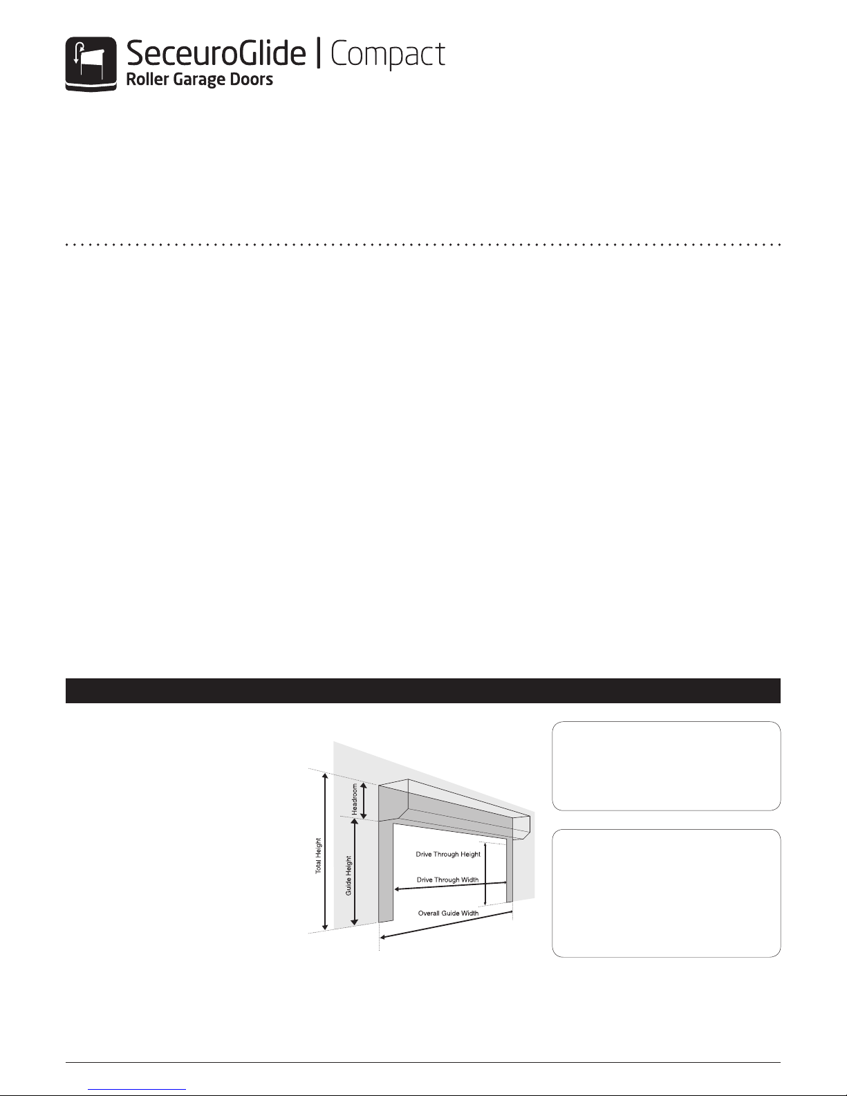
03. PREPARE THE OPENING
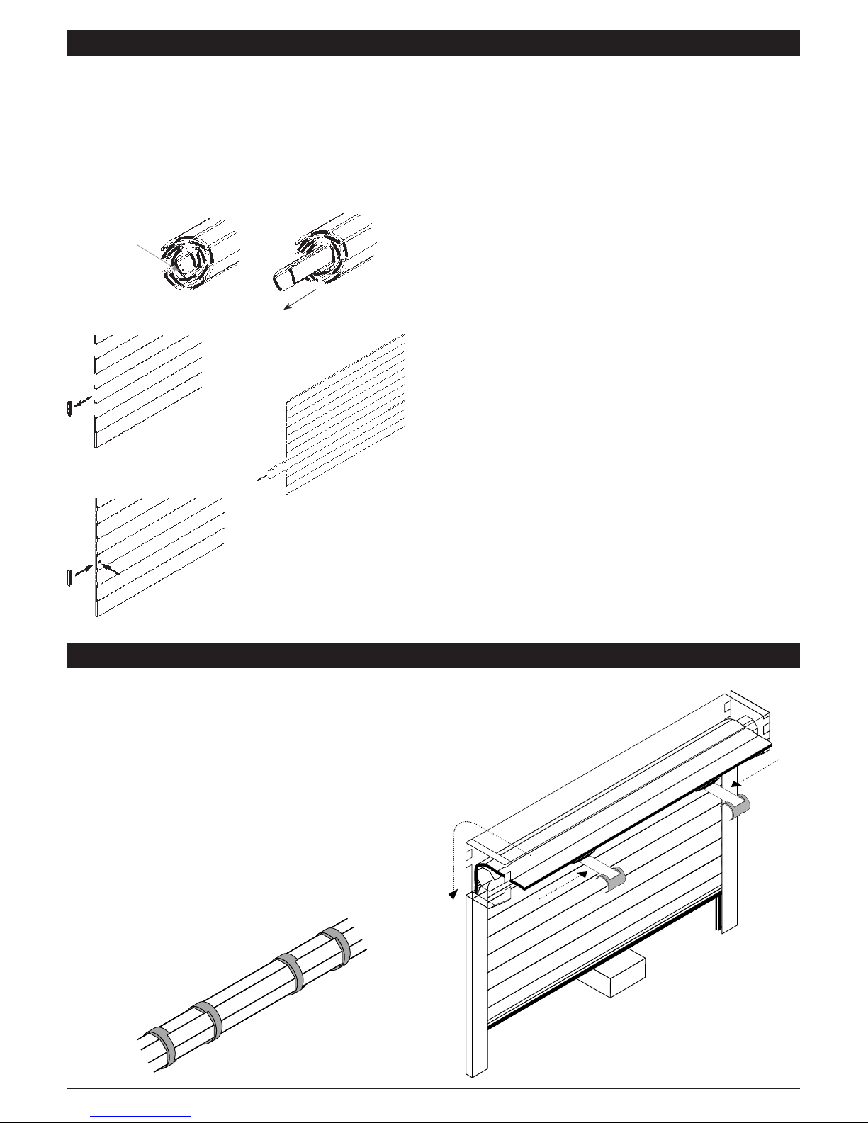
04. PREPARE THE GUIDE RAILS
Check:
i. Structure is sound/even & can carry the weight of the door
ii. No obstacles in fitting footprint eg. no sharp objects, pipes,
cables, bumps etc. sticking out from the pillars, lintel or header
to twist the guides, distort the fascia or catch on the curtain
iii. Floor is flat/level
If necessary install a sub-frame to ensure secure, flush and
level fixing (Recommended minimum 70 X 70 PAR).
If the guides require cutting down refer to the ‘Widths and
Heights’ information in Section 1. If face fixing where possible set
the guide height at least 50mm above the structural opening
height to maximise drive through height.
i. Position guides
ii. Drill guide fixing holes (min 4) 7mm pilot hole 13mm outer
hole, avoid mortar joints and edges of bricks etc.
REVEAL
DRILL
OR FACE DRILL
GUIDE/ DOOR
HEIGHT
BOTTOM SLAT HANG
DOWN 50mm
DRIVE THROUGH
HEIGHT N.B. Guides are handed. If cutting guides cut excess length from
bottom of guide.
REVEAL FIX
INTERNAL SIDE
3mm 7mm
FACE FIX
INTERNAL SIDE 13mm
7mm
05. FIX GUIDE RAILS & AXLE ASSEMBLY
N.B. Before positioning check that there are no sharp objects or
bumps sticking out from the pillars, lintel or header to twist the
guides or distort the fascia.
i. Slot end plate lugs into guides (see Drawing A) remembering
the guides are handed (check guide terminals are in place, see
Drawing B)
ii. Position guides and fascia against opening
iii. Hold or prop securely the assembly in position
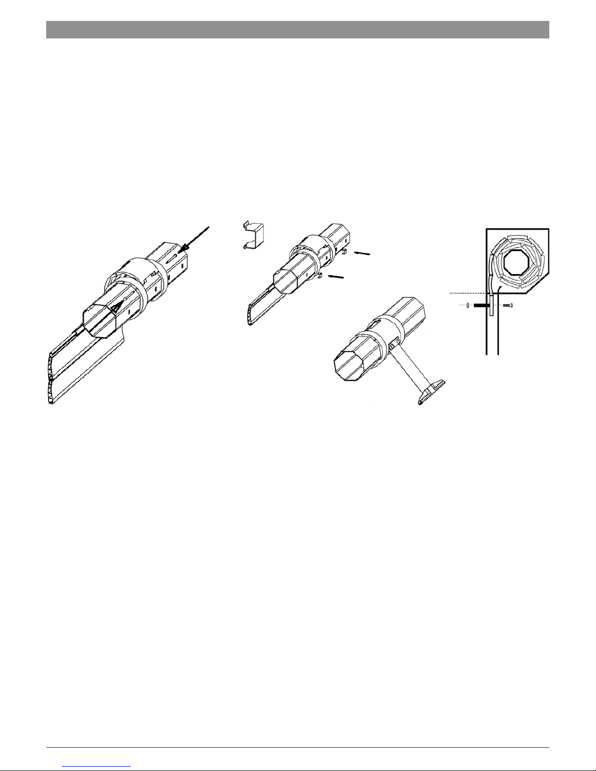
iv. Drill fixing holes (min 4 in guides and 2 in each end plate)
v. Fix guides/end plates with minimum No. 12 x 21/2”
countersunk screws (and plugs) to masonry/timber or 12 x
1” self tapping screws to steel. Fix fascia every metre with
minimum 12 x 1” screws. Penny washers supplied must be
used to spread fixing load on end plates and fascia
vi. Stick brush strip to inside bottom edge of 90° fascia (optional
see Drawing B)
N.B. Extreme care should be taken while manoeuvring the
door into place to avoid the possibility of snapping the end
plate lugs. It is imperative that fixings are put through the end
plates into the wall as the aluminium lugs are not designed to
carry the weight of the door.
A
Lug
N.B. Axle assembly
must be level
www.samsondoors.co.uk
0800 328 6250
www.samsondoors.co.uk

4
August 2016 Issue 1 SGCP16
Check:
i. Back faces of guides and end plates are flush and untwisted
(see Drawing C)
ii. Guides are vertical/parallel/same height, this is essential for the
bottom slat transmitter (if fitted) to function correctly.
iii. Axle cap is butting up against the end plate and held in place
with at least 2 rivets (see Drawing B)
iv. Collars are correct way around
(see Drawing D)
v. Secure Motor Power Lead with Cable Clips so that it is tight
against the end plate – see Drawing E. You must ensure that
you allow for a drip loop in the motor cable to prevent water
from running down the cable and into the motor. Spare cable
ties can be attached to the motor cable to act as drip loop to
prevent water entering the motor.
C
Fit brush strip
Fix the 90º fascia back securely
B
Axle Cap
Guide
Terminal
E
D
06. FITTING EMERGENCY OVERRIDES
1
Left Hand viewed
from centre of door
2 3
Right Hand viewed
from centre of door
Right Hand viewed
from centre of door
Possible Override Exit Options
N.B. The factory assembled options 1 & 2 are recommended
05. FIX GUIDE RAILS & AXLE ASSEMBLY (CONTINUED)
www.samsondoors.co.uk
0800 328 6250
www.samsondoors.co.uk

5
August 2016 Issue 1 SGCP16
06. FITTING EMERGENCY OVERRIDES (CONTINUED)
A) Standard Manual Override
Standard Manual Override Internal Fitting
(see Drawing A):
i. Drill hole for override eye through end plate flange
ii. Insert override eye in hole in motor adjacent to limit adjusters
iii. Insert and tighten the holding screw and washer from above
iv. Hook crank handle in eye
v. Secure clear of shutter with crank handle clip
B) Optional Low Level External Override
N.B. It is suggested that the override exits as per diagram 2 on the previous page.
Please note more detailed installation instructions are supplied in the override kit.
i. Drill hole for override eye through end plate flange
ii. Insert hexagonal bar through hole in motor adjacent to limit adjusters (see
Drawing B)
iii. Mark position for hole through wall adjacent to guide rail at bottom end of
crank (see Drawing C). Crank can exit at 90° if door tight to return wall (see
Drawing D). Length of shaft can be shortened to adjust operating height.
iv. Drill 22 mm hole through the wall (see Drawing C)
v. Secure universal joint bracket to wall
vi. Insert tube (cut to length) and fix plate to wall
(see Drawing E)
N.B. Fixings not supplied.
Externally Fitted Compact Roller Garage Door
The crank handle is not permanently attached but is
only inserted as required (also see Section 10)
A
500mm
LOCK PLATE AND TUBE
E
D
WALL
BC
22mm
R clip
To operate the Low level override from
inside the garage remove the R clip and
then wind the handle.
www.samsondoors.co.uk
0800 328 6250
www.samsondoors.co.uk

6
August 2016 Issue 1 SGCP16
07. CURTAIN ADJUSTMENT (REDUCING HEIGHT/MAKING REPAIRS)
08. INSTALL THE CURTAIN IN THE GUIDES, ATTACH TO AXLE & FIT STOPS
If the door needs to be reduced in width it will need returning to
the supplier.
The curtain needs to be the correct height for the door to lock
properly (if too tall remove slat(s) – If too short notify supplier).
Check you have the correct number of slats in the curtain for the
guide height (particularly if you have shortened the guide height)
and adjust the curtain accordingly.
Remove slat by carefully snipping ear off end lock before sliding
out slat. Preferably take slats off from the top of the curtain to save
having to remove and refit bottom slat. Either roll curtain out on a
flat and protected surface such as the bubble wrap and/or cardboard
packaging in which the curtain is delivered, or do as below.
REPAIR PROCEDURE
Re-secure endlocks with
2 No. 4mm x 8mm rivets supplied
Slide out damaged
slat(s), slide in new slats
Remove end lock
Slide out slats
Snip ear off
endlock to release
slats
A
Feed in Curtain
B
Slide in
Locking
Springs
i. Check that there are at least 4 pairs of compact locking
collars on the axle and that each pair of collars has the cut-
out towards the centre and line up with other pairs of collars
along the axle (see Drawing A). One pair must be approx.
150mm in from each end of the axle and the remaining pairs
evenly spaced.
ii. Lift coiled curtain up level with axle and feed bottom of
curtain into guide (see Drawing B)
iii. Slowly unroll curtain and gently lower onto a tool box or block
(see Drawing B)
N.B. Do not allow the curtain to free fall over the axle as this
will result in damage to the curtain.
www.samsondoors.co.uk
0800 328 6250
www.samsondoors.co.uk

7
August 2016 Issue 1 SGCP16
C
08. INSTALL THE CURTAIN IN THE GUIDES, ATTACH TO AXLE & FIT STOPS (CONTINUED)
D
E
F
iv. Slide the locking springs with semi-circular attachment
bracket onto the top slat. Rotate the axle with the manual
override until the attachment holes in the collars are accessible.
Use the special attachment pins as supplied to attach the semi-
circular attachment bracket between the collars.
N.B. You must use the second hole. Ensure that the pin is fully
engaged in the attachment bracket (it should click into place)
to prevent product failure (see Drawing C).
v. Fit small retention clips into the cut-outs in the axle to stop
the locking assemblies moving along the axle. The clips do
not have to be tight up against the collar. (see Drawing D)
vi. Use override to raise door sufficiently to remove toolbox/
block. Ensure that the semi-circular curtain attachment
bracket coils up flush with the collars (see Drawing E).Leave
door in partially open position.
vii. Drill 8mm hole close to edge of bottom slat and fit stops
(preferably to the outside, see Drawing F). It is essential the
stops are fitted for health and safety reasons
www.samsondoors.co.uk
0800 328 6250
www.samsondoors.co.uk

8
August 2016 Issue 1 SGCP16
09. CURTAIN LOCKING & SETTING MOTOR LIMIT SWITCHES
Compact Roller Garage Door is manufactured with the curtain
height to suit the length of guide supplied. The door will not lock
down properly if the curtain is either too tall or too short. If the
guide height has been adjusted on site, check that the top of
the curtain is neither below the top of the guide nor more than
one slat above (see Drawing A & B below). Both limits require
setting along with a final adjustment of the locking springs. We
recommend the use of a Test Lead* to set the limits and to
make the final locking adjustment. For external fits the two
hole 45° crank handle can be inserted and removed as required.
To set the limits remove the cap covering the white/ yellow limit
switches, fully press in both switches (they will lock in position –
see Motor Drawings below) and then proceed as follows.
*Should you not have a test lead use the override to set the limits.
N.B. Incorrect setting of the limits risks damage to the motor,
curtain and attachment devices.
Closed / down limit setting and locking spring adjustment:
i. Send down with the test lead so that the curtain is fully down
and the top slat is pushed forward so that it touches the
fascia. The metal attachment springs should be taut but not
bent or distorted (see Drawings A, B & C).
ii. Now set the motor closed/down limit (see left-hand/right-
hand motor text boxes).
Open/up limit setting
i. Send the door up with the test lead to open/up position and
stop (50mm of curtain should still be in guide. Stops should
be 10mm below fascia – see Drawing D).
ii. Press and release the open/up limit switch
A
C
B
Open/up
STOP
MIN
10mm
D
Fully press in to
set limits. Release
limit when set
N.B. Always replace the yellow limit
switch cover cap once limits are set.
Close/down
Open/up
Left Hand Motor
Fully press in limit switch to activate. Press and release switch when door
has been set to stop in correct position. The yellow limit switch activates the
OPEN/UP limit. The white limit switch activates the CLOSE/DOWN limit.
Right Hand Motor
Fully press in limit switch to activate. Press and release switch when door
has been set to stop in correct position. The yellow limit switch activates the
CLOSE/DOWN limit. The white limit switch activates the OPEN/UP limit.
www.samsondoors.co.uk
0800 328 6250
www.samsondoors.co.uk

9
August 2016 Issue 1 SGCP16
Internal Fitting
Fit optional 45 degree lid. A slot may have to be cut into the lid to pass over the override eye.
10. COMMISSIONING
Final Checks
i. Remove any protective plastic coverings.
ii. Wipe curtain & guides with damp cloth.
iii. Touch-up any small scratches.
iv. Check all electrical & operating equipment is installed
and functioning correctly (especially the safety edge) and
complete CE marking label and paperwork.
v. Check direction handle needs winding to open door and fit
appropriate label supplied to crank handle.
vi. If the door is fitted externally apply a bead of silicone around
the box edge to prevent water ingress.
vii. Attach stops to bottom slat 230mm in from the outer edges
of the bottom slat.
N.B. Check the front of the curtain to make sure that it is not
rubbing on the fascia etc.
The manual override will not function after the door is operated
by remote control, until the power to the motor has ‘timed out’.
This will take a few moments to occur.
If you wish to demonstrate the manual override immediately after
opening the door press either the stop button on the handset or
simulate a power cut by switching off the power to the Control Unit.
If a low level external override is fitted or the door is fitted
externally remind customers to keep the override handle in a
convenient place (not in the garage if no other way in!)
Upon completion it is your responsibility to train the customer
how to operate the door correctly and safely and provide them
with the operating and maintenance instructions supplied.
If you require any on site technical assistance including
repair or maintenance queries please call 01524 772400
or email technical@swsuk.co.uk
Control unit set up instructions are provided
in the control panel accessory box along with
the control unit and you can also access them
digitally using this QR code or link:
www.sws.co.uk/easysetup
11. TECHNICAL ASSISTANCE
www.samsondoors.co.uk
0800 328 6250
www.samsondoors.co.uk
Table of contents
Other SWS Garage Door Opener manuals
Popular Garage Door Opener manuals by other brands

White Rose
White Rose FOCUS 600 Installation and operating manual

Chamberlain
Chamberlain Merlin Professional MR1000 Installation and operating instructions

Genie
Genie QuietLift 2040C Operation and maintenance manual

CAME
CAME V900E STANDARD INSTALLATION

GarageAce
GarageAce R3 installation instructions

Tormatic
Tormatic W-600 manual