4
Please note: The validity of the LPCB certification is contingent
upon the roller garage door being installed in accordance with the
requirements of LPS 1175 (see section 2 for further details).
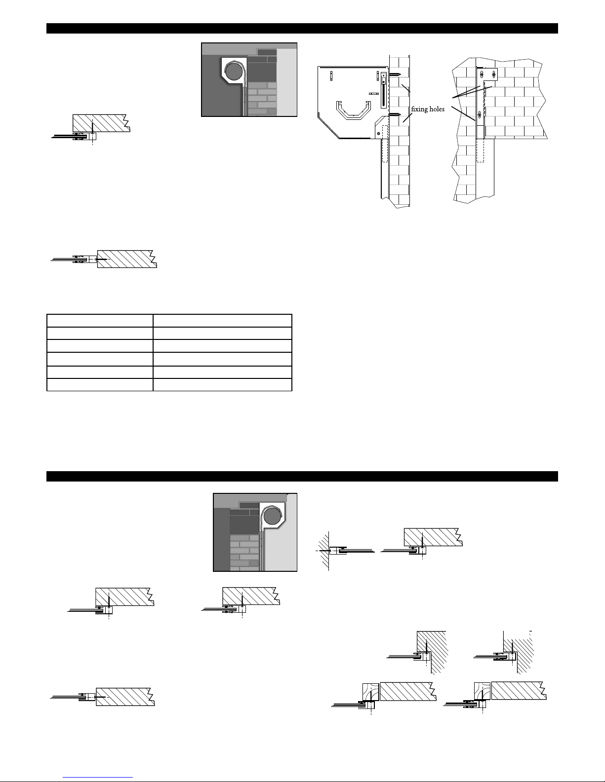
If the guides require cutting down refer to the information at
the start of Section 1 and also section 6 for reducing the curtain
height. If face fixing where possible set the guide height at least
55mm above the structural opening height to maximise drive
through height.
i) position guides
ii) drill guide fixing holes 7mm pilot hole 13mm outer hole
(min 4) avoid mortar joints and edges of bricks etc.
LPS 1175 compliant doors
Doors which are compliant with LPS 1175 will be supplied with a
bottom slat anchor system prefitted to the bottom slat and guide
rails.
Once the guide rails have been fastened in place the bottom slat
anchor guide insert must be fastened to the floor as shown below.
Bottom Slat
Hang Down
55mm
Drive Through
Height
Guide/Door
Height
REVEAL FIX
INTERNAL
SIDE
7mm
13mm
75mm
4. PREPARE THE GUIDE RAILS:
FACE
DRILL
FACE FIX
13mm
7mm
75mm
INTERNAL
SIDE
N.B. 90mm guides are handed
90mm
Check:
i) structure is sound/even & can carry the weight of the door
(curtain weight is approximately 5kg/m2 and allow an extra
15kg for the guides, end plates and axle assembly).
ii) no obstacles in fitting footprint e.g. no sharp objects, pipes,
cables, bumps etc. sticking out from the pillars, lintel or
header to twist the guides, distort the fascia or catch on the
curtain
iii) floor is flat/level
If necessary install a sub-frame to ensure secure, flush and level
fixing. (Recommended minimum 70 X 70 PAR)
3. PREPARE THE OPENING:
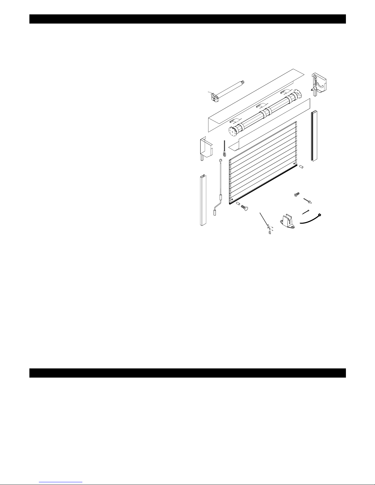
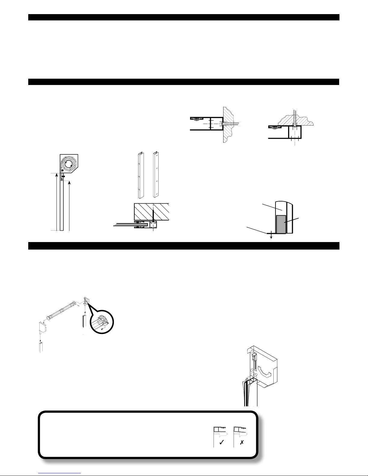
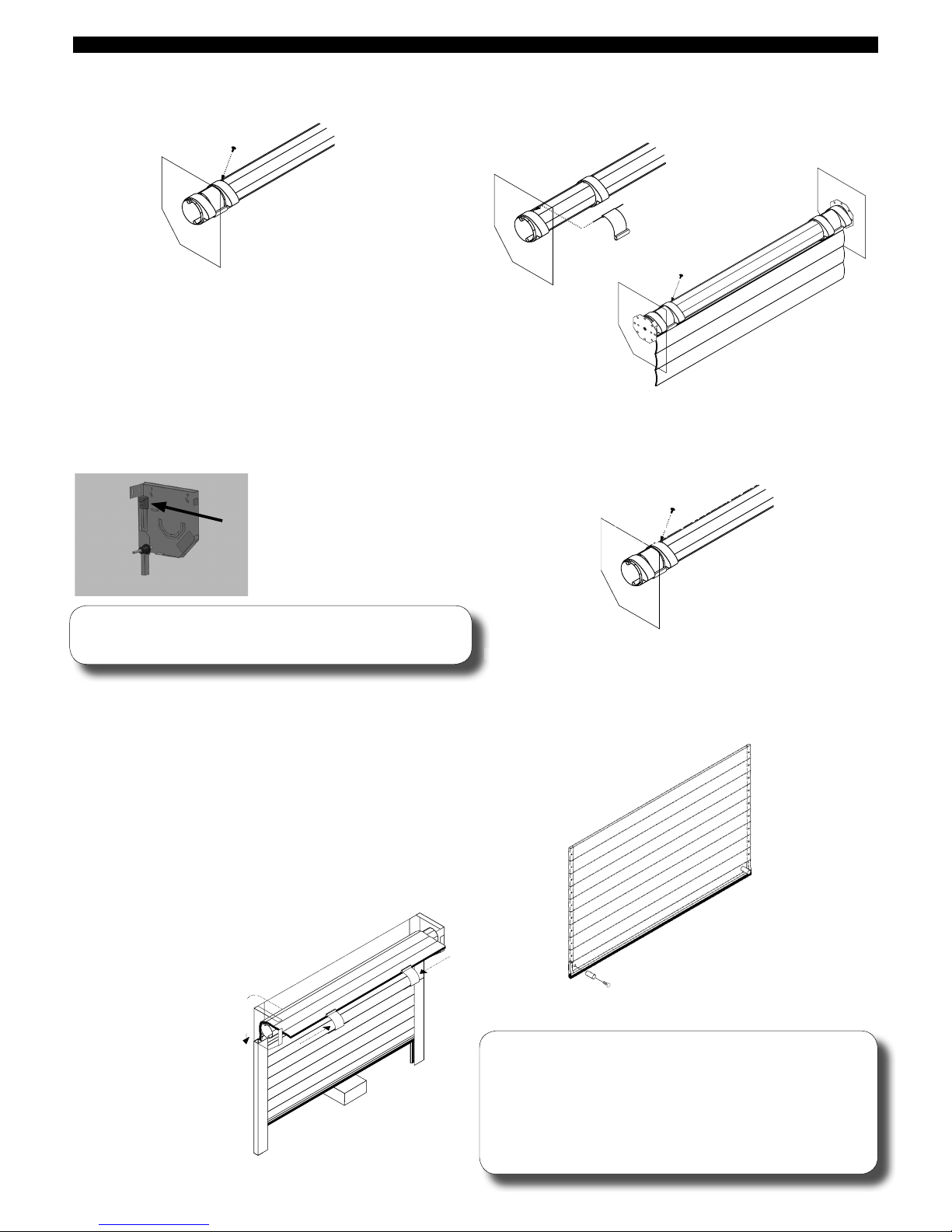
5. FIT END PLATES, AXLE ASSEMBLY, GUIDES (& OPTIONAL FASCIA):
N.B. When fitting doors with 300mm end plates and the guide
height is more than 2300mm it is important that you check that
the lintel does not bow inwards or have any projections that may
catch on the curtain. If in doubt pack the guides and end plates out
by at least 10mm.
i) slot end plates into guides (and fix optional fascia if supplied) -
see drawing A
If using 90mm guides make sure the back face of the end
plate is in line with the back of the guide.
3 rivets should be used to fasten the fascia to each end plate.
Doors compliant with LPS1175 will be supplied with penny
washers which the rivets must be fastened through.
ii) position guides, end plates (and optional fascia) against/in
opening
iii) hold or prop securely in position
iv) drill fixing holes (minimum of 4 in guides and 2 in each end
plate if not LPS 1175 compliant)
v) fix guides/end plates with minimum No. 12 x 21»´
countersunk screws (and plugs) to masonry/timber or 12 x
´VHOIWDSSLQJVFUHZVWRVWHHO)L[IDVFLDHYHU\PHWUHZLWK
PLQLPXP[´VFUHZV3HQQ\ZDVKHUVPXVWEHXVHGWR
spread fixing load on fascia. If there is nothing to fix to, 50 x
20 box section should be ordered to reinforce the fascia and
prevent deflection which may damage the curtain. Drill and
pop rivet from inside the fascia ensuring that the rivet leaves a
smooth surface.
vi) ease open top of guides – see drawing C
Before proceeding any further check:
a) back faces of guides and end plates are flush and untwisted – see drawing B
b) that the distance between the outside edges of the guides is 90mm more than the curtain
width
c) ensure that the distance between the outer edges of the end plates is
equal to the stated overall width of the door.
Drawing B
Drawing A
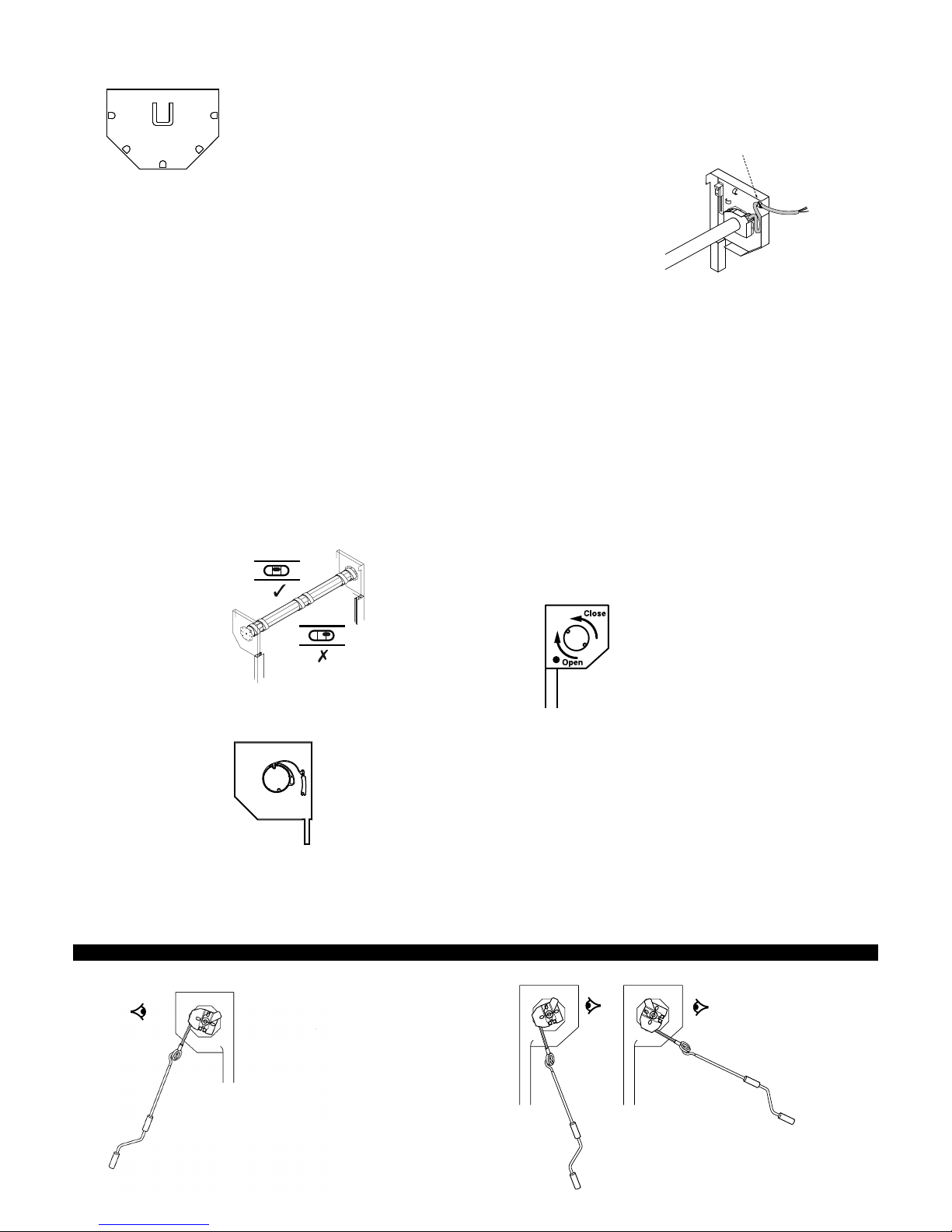
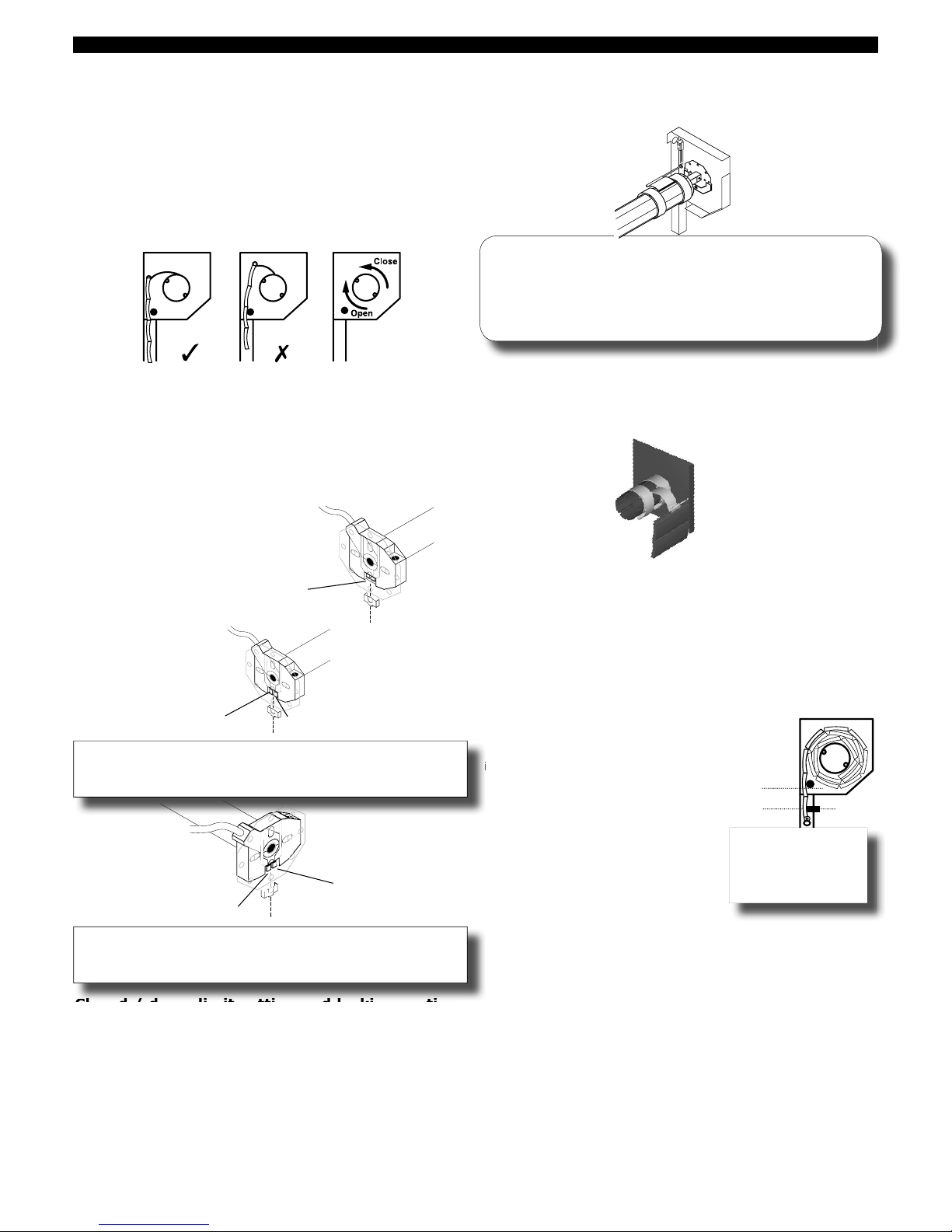
The dummy end octagonal
fixing plate is supplied in the
accessory box. The plate must
be fitted to the appropriate
end plate (not the motor side)
before installation of the axle.
Drawing C
REVEAL
DRILL
FIXED TO FLOOR WITH
MINIMUM OF 1 1/2 INCH No.12
GUIDE INSERT FIXED TO GUIDE
GUIDE RAIL
High winds and high temperatures can cause increased deflection of the door. It is the installer's responsibility to ensure that the door is
packed off the wall sufficiently to allow for door movement during these extreme weather conditions.