Swytch eBike Conversion Kit User manual
Installation
1
Instruction
Manual

Got an accessory?
Scan here for instructions.

3
Introduction
These are the original instructions for the Swytch eBike Conversion Kit. This is the Swytch
Manual Version 007. The most up-to-date version of this manual can be found here and
this should be consulted for any changes. swytchbike.com/manual.
Please read this manual as it contains important safety information and guidelines for how
to get the most out of our Swytch Kit.
Safety Warnings
To ensure a safe and trouble-free experience when using your Swytch Conversion Kit
please follow the guidelines below:
Kit intended use
The Swytch Kit is designed for roads and well-made paths. It’s not intended for drops of
more than 10cm, stunts, cross-country riding, or extreme sports. Misuse may lead to the
failure of some components and void your warranty.
The product must be used in compliance with your local laws and legislation.
Fully charge before first use
As soon as you receive your kit fully charge your Power Pack, the light will go from red to
green. Do this before you start fitting the Kit.
Never leave on charge for longer than necessary
The Power Pack is perfectly safe for home use, but the charger and battery will
gradually and naturally heat up when it’s plugged in. Avoid leaving your Power Pack on
charge for longer than necessary as this can lead to reduced battery life.
Power Pack Warnings
When using, please follow the manual instructions. The battery must not be
exposed to temperatures below -10°C or above 40°C. The battery contains
dangerous substances, and you must not disassemble, impact, or soak it in water. Only use
the charger provided to charge the battery and when in storage you must charge every 90
days.
The handlebar mount handle must be fully engaged with the Power Pack
The Power Pack must be fully connected within the mount for correct operation. The Power
Pack should sit vertically within the mount with the logo facing forwards and the yellow
connector at the top.
Introduction

4
Tighten up before riding
Whether it’s your first ride or your hundredth ride, please ensure all nuts, screws and bolts
are tight before taking off on the road. Any loose parts could result in the motor wheel
coming off while riding - please be careful. Every 100 km, check your wheel spokes are
tight to ensure that the wheel remains secure.
Maintain your bike
For a safe ride on any bicycle, it’s important that the bike is well-maintained and in good
working order. Regularly check and maintain the condition of your bike.
Placing any metallic or conductive objects into the charge port other than the
charger may cause electric shock, fire or other injury. Don’t connect the charger if water,
ice or condensation is in the charge port.
Before you ride your Swytch Bike for the first time, please be sure that it has been cor-
rectly assembled. You’ll find step by step instructions in this manual. For further help and
support visit our help centre - support.swytchbike.com
Spares
Only genuine replacement parts for safety-critical components must be used. There are no
consumables or lubricants necessary for the Swytch Kit. Please contact our help centre for
more information about spares.
Warnings
Throughout the manual these callouts warn about situations that could cause death,
serious injury and/or heavy material damage if you don’t follow the safety
instructions.
Get in touch
Before you ride your Swytch Bike for the first time, please be absolutely sure that it has
been correctly assembled. You will find step-by-step instructions in this manual. For
further help and support visit our help centre here - support.swytchbike.com.
!
Introduction

5
00
Table of Contents
01
In the Box
04
Using Your Kit 05
Troubleshooting
02
Installation
06
Kit Care
03
Brompton
Kit Checklist
Tools Required
p.7
p.8
Error Codes
Motor Wheel
Pedal Sensor
Magnetic Disc(s)
Mount & Bracket
Swytch Motor Wheel
Magnetic Disc(s)
Pedal Sensor
Mount & Bracket
Base Display
Connecting Up
Routing Cables
Power Pack Intro
Starting Your Ride
Power Pack Settings
Checking Your Battery
Ending Your Ride
Charging Your Kit
p.10
p.15
p.23
p.25
p.28
p.29
p.31
p.40
p.41
p.43
p.45
p.46
p.47
p.49
p.50
p.51
p.52
p.54
p.54
p.55
p.33
p.34
p.36
p.37
p.38
Maintenance
Warranty Terms
Torque Washer
Magnetic Disc(s)
Pedal Sensor
Mount Placement
Cable Routing

Swytch Help Centre
01
In the Box
1. Kit Checklist
2. Tools Required

7
Kit Checklist
In the Box
Power Pack Motor Wheel Mount
Bracket, Spacers & Screws Base Display Magnetic Disc(s)
Pedal Sensor Charger Cable Ties
Use this list to get all the parts
ready before you start.
*Please note that this doesn’t include any accessories.
1.

8
In the Box
Tools Required
Allen Key Set Tyre Levers Scissors
Bicycle Pump Adjustable Spanner Ruler
You’ll need to use the following tools
to install your Kit. Please note that
these are not provided.
2.

Swytch Help Centre
02
Installation
1. Swytch Motor Wheel
2. Magnetic Disc(s)
3. Pedal Sensor
4. Mount & Bracket
5. Base Display
6. Connecting Up
7. Routing Cables
10
Installation
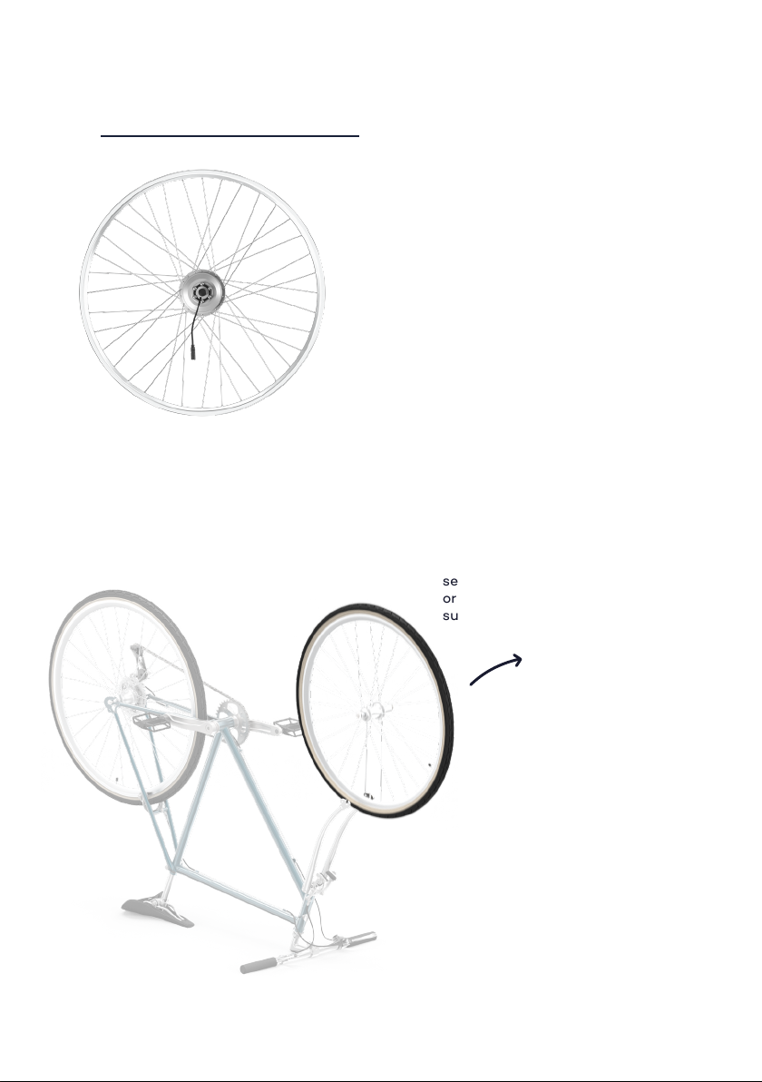
1.
1. Remove your front wheel
Swytch Motor Wheel
1.1
Your Swytch motor wheel has been
built to the size and colour you
specified in the Order Portal. The
wheel incorporates the 250W motor
hub which is used to power your bike
so it’s important to assemble it
securely into your forks.
Turn your bike upside down.
Loosen your existing front wheel
and remove it.
Note
These steps depend on the brand
and type of bike you have. Please
see the manufacturer’s instructions
or visit support.swytchbike.com for
support.
Table of contents
Other Swytch Bicycle Accessories manuals


