SY-HDBT-70S EXTENDERS
9 www.sy.co.uk
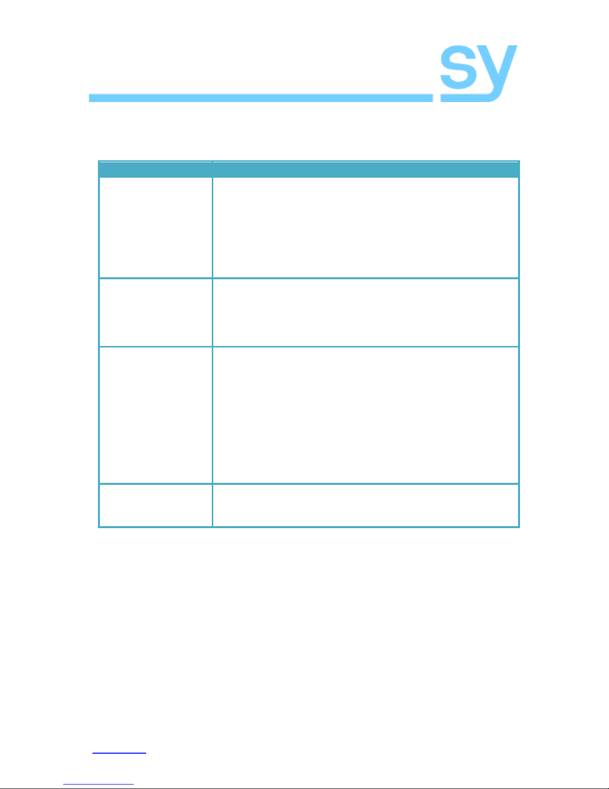
Safety Instructions
To ensure reliable operation of these products as well as protecting the safety of any person
using or handling these devices while powered, please observe the following instructions.
1. Use the power supplies provided. If an alternate supply is required, check
Voltage, polarity and that it has sufficient power to supply the device it is
connected to.
2. Do not operate either of these products outside the specified temperature
and humidity range given in the above specifications.
3. Ensure there is adequate ventilation, as these products generate heat while
operating.
4. Repair of the equipment should only be carried out by qualified professionals
as these products contain sensitive devices that may be damaged by any
mistreatment.
5. Only use these products in a dry environment. Do not allow any liquids or
harmful chemicals to come into contact with these products.
After Sales Service
1. Should you experience any problems while using these products, firstly refer
to the Troubleshooting section in this manual before contacting SY Technical
Support.
2. When calling SY Technical Support, the following information should be
provided:
Product name and model number
Product serial number
Details of the fault and any conditions under which the fault occurs.
3. These products have a two year standard warranty, beginning from the date
of purchase as stated on the sales invoice. Online registration of these
products is required to activate the full three year extended warranty. For full
details please refer to our Terms and Conditions.
4. SY Product warranty is automatically void under any of the following
conditions:
The product is already outside of its warranty period
Damage to the product due to incorrect usage or storage
Damage caused by unauthorised repairs
Damage caused by mistreatment of the product
5. Please direct any questions or problems you may have to
before contacting SY Electronics.