SY Xcalibur 14 User manual

SY Electronics Ltd., 7 Worrall Street, Manchester, M5 4TH, United Kingdom
Tel: +44 (0)161 868 3450 – Web: sy.uk
Xcalibur 14 (set)
User Manual
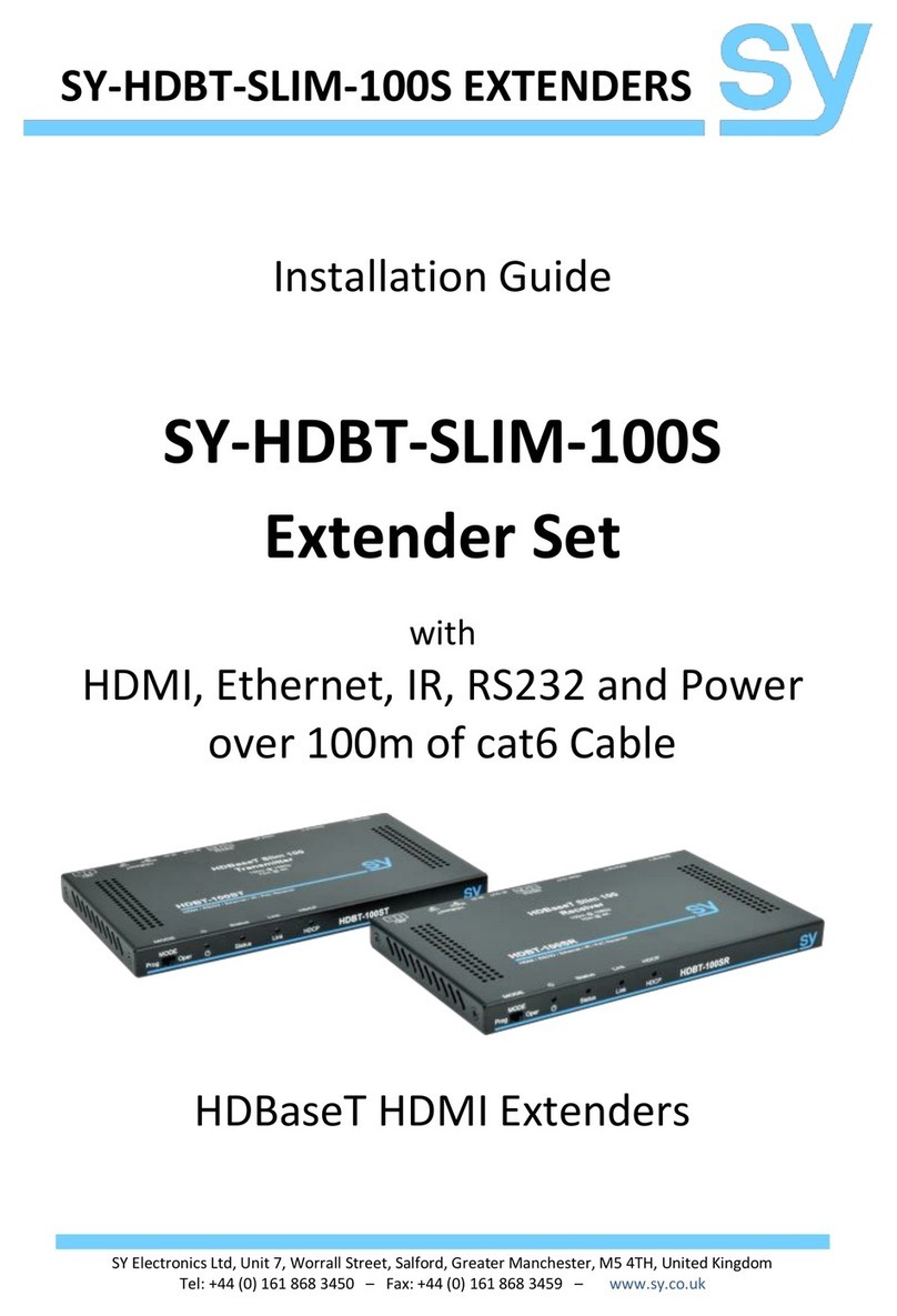
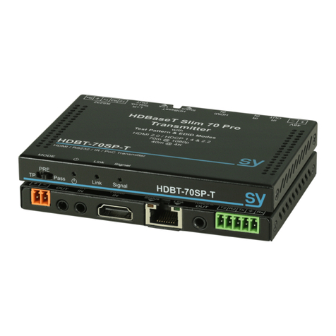
Excalibur 14 Splitter (HX150-14-18G)
Excalibur 11 Receiver (HX150-11-18G-R)
1x4 HDMI 2.0 Extender
150m @1080p or 120m @4K
HDMI 2.0 (4K60 4:4:4), Down-Scaler, Test Pattern, VKA,
EDID & HDCP control, Audio de-embed, PoC

sy.uk 2V1.0
Thank you for purchasing the PRODUCT.
This PRODUCT is designed with the professional AV installers in mind. The many extensive
features assist in system integration, validation, and maintenance.
Installation precautions
This product has special circuitry to protect it against moderate surges and static discharges.
However, to ensure reliable operation and long service life, it is important to take the
necessary precautions against any spikes, surges and static discharges.
Place the units away from heat sources and allow adequate ventilation.
Shielded cable and in particular cat6, cat6a or cat7 is highly recommended. As much as
possible cables should be routed away from any noisy sources and avoiding long runs in close
proximity to AC mains cables.

V1.0 3sy.uk
CONTENTS
FEATURES 4
CONNECTORS AND CONTROLS 5
MAIN SPLITTER UNIT 5
Front 5
Rear 5
RECEIVER 6
Front 6
Rear 6
RJ45 Status LEDs 6
USING THIS PRODUCT 7
DE-EMBED AUDIO OUTPUTS 7
Balanced Analogue Audio output 7
Coax (S/PDIF) Audio Output 7
EDID OPTIONS 8
RS232 CONTROL COMMANDS 9
SYSTEM COMMANDS 9
4K DOWN-SCALING 10
HDCP OPTIONS 10
OUTPUT STREAM CONTROL 11
EDID SETTINGS 11
TEST PATTERN 13
VIDEO KEEP-ALIVE (VKA) 13
SENDING RS232 COMMANDS THROUGH THE RECEIVERS 13
Bypass Command Responses 14
SYSTEM CONFIGURATION 15
RJ45 WIRING 15
IR PASS THROUGH 16
FACTORY DEFAULTS 16
SPECIFICATIONS 17
GENERAL 17
ENVIRONMENTAL 17
PHYSICAL 17
PACKING LIST 17
SAFETY INSTRUCTIONS 18
AFTER SALES SERVICE 18

sy.uk 4V1.0
This 18Gbps HDMI 1x4 Splitter/Extender can distribute one HDMI source to up to four displays
using Xcalibur Receivers. The transmission distance can be up to 150m for 1080p or 120m for
4K2K.
The Xcalibur 14 also extend bi-directional IR & RS232 signals, together with many features such
as 4K 1080p down-scaler, Test Pattern generator, VKA (video Keep Alive), HDCP and EDID
management, as well as audio outputs. The Xcalibur Receiver unit also provides a de-embedded
stereo L/R audio output.
IMPORTANT: The Xcalibur 14 set works with all Xcalibur product range. They are not compatible
with HDBaseT products.
Features
HDMI 2.0 compatible – 18Gbps signal bandwidth
Supports all PC and HDMI resolutions up to 4K60 4:4:4
150m for 1080p or 120m for 4K, using single Cat5e, 6, 6a, 7
Built-in Test Pattern feature with several pattern types and resolutions
Video Keep-Alive (VKA) option prevents displays entering standby mode
4K 1080p Down-Scaler per output– Set or Auto option for any 4K to 1080p
HDCP 1.4 and HDCP 2.2 compliant
HDCP and EDID management
Supports HDR, HDR10, HDR10+, HDR12, HLG and Dolby vision
HDMI audio support up to 7.1 surround sound
De-embedded Audio – Digital and balanced Analogue stereo (L/R) outputs
Each Receiver unit provides stereo audio (L/R only)
Selectable RS232 routing for 3rd party commands to each output or all outputs
RS232 pass-through for 3rd party control commands
Bidirectional global IR pass-through to and from all receivers
PoC - The Receivers are powered over the cat5e/6/6a/7 cable from the transmitter
Only one 24V PSU required

V1.0 5sy.uk
Connectors and Controls
Main Splitter Unit
Front
Name
Description
Power LED
Lit – Xcalibur-14 Splitter is powered
IN
Lit – Valid HDMI signal at the input
LOOP
Lit – Valid HDMI signal at the HDMI LOOP OUT connector
OUTPUT 1 ~ 4
Lit – Valid Link status at the HX outputs
Rear
Name
Description
RS232
RS232 input for controlling the transmitter and sending commands to the remote
Receiver RS232 ports
IR IN
Input for IR control to all the Receivers
IR OUT
IR signal output from the Receivers
COAX
S/PDIF digital audio output
5-WAY BLOCK
Balanced analogue stereo audio output
EARTH
Earth point for system ground
SWITCH
On/Off switch for 24V DC input
DIP Switches
Manual EDID setting options (Also Test Pattern selection)
HDMI IN
HDMI input from source device
HDMI LOOP OUT
HDMI output to local display device
HX OUTPUTS 1~4
HX RJ45 outputs - PoC and HX signal outputs for up to four Receivers
24V
24V DC PSU input (2.1mm barrel jack)

sy.uk 6V1.0
Receiver
Front
Name
Description
Power LED
Lit – Receiver is powered
SERVICE
Micro USB for configuration or update
Rear
Name
Description
24V
24V DC Power input – not required when used with Xcalibur-14
HX (Cat6 Input)
Cat6 cable input from the Xcalibur-14 splitter
HDMI OUT
HDMI output to the display device
AUDIO OUT
Stereo (L/R) analogue audio output
IR IN
Input for IR control to the Xcalibur-14
IR OUT
IR control signal output from the Xcalibur-14 unit
RS232
Bi-directional RS232 control supporting Tx and Rx signals only
RJ45 Status LEDs
The RJ45 connectors on both the Xcalibur-14 Splitter and Receiver units also provide LED
indication of the cable link status and data signal status:
RJ45 LEDs
Meaning
GREEN LED
Lit when there is a valid link status between the Transmitter and the Receiver:
Solid: Good Link status
Flashing: Poor Link status
Off: No link detected
YELLOW LED
Lit when there is a valid data signal between the Transmitter and the Receiver. This
LED also indicates the HDCP status:
Solid: HDCP Present
Flashing: No HDCP
Off: No data signal

V1.0 7sy.uk
Using this Product
This Xcalibur-14 Splitter Extender product is designed to function only with the Xcalibur
Receivers (provided with the set). Important: The HX ports are not compatible with HDBaseT
devices.
1. Connect the video source to the HDMI input.
2. Connect the HX outputs to the HX input of the Receivers using Cat6 cable.
3. If a local display is required, connect it to HDMI OUT.
4. Connect the 24V DC PSU to the Xcalibur-14 (This will power the 4x Receiver units too).
5. Connect any external controls that are required to their respective ports: i.e. RS232 or IR.
6. Connect any audio amplifiers to the audio connections, as required.
7. Power up the system.
De-embed Audio Outputs
Balanced Analogue Audio output
The differential (Balanced) analogue audio output only provides the Front Left and Front Right
audio channels. When connecting to an unbalanced audio input, only connect to the L+, R+, and
Ground signal pins on the five way connector as shown in the following diagrams:
Figure 1 – Balanced Audio Out
Figure 2 – Unbalanced Audio Out
Coax (S/PDIF) Audio Output
The COAX audio output provides de-embedded digital S/PDIF audio data. It always outputs the
same number of audio channels as is present in the input HDMI signal.

sy.uk 8V1.0
EDID Options
The SY-HX150-14-18G splitter has a 5 way DIP switch, providing the following 32 EDID options.
In the following table U means switch set to Up position (indicated as 1 on the unit); and D means
switch set to Down position (indicated as 0 on the unit).
EDID Mode
EDID Resolution
Audio Channels
Audio Format
UUUUU
1080p60
2.0
Stereo
UUUUD
1080p60
5.1
Dolby DTS
UUUDU
1080p60
7.1
HD Audio
UUUDD
1080i60
2.0
Stereo
UUDUU
1080i60
5.1
Dolby DTS
UUDUD
1080i60
7.1
HD Audio
UUDDU
1080p60 3D
2.0
Stereo
UUDDD
1080p60 3D
5.1
Dolby DTS
UDUUU
1080p60 3D
7.1
HD Audio
UDUUD
4K30 4:4:4
2.0
Stereo
UDUDU
4K30 4:4:4
5.1
Dolby DTS
UDUDD
4K30 4:4:4
7.1
HD Audio
UDDUU
4K30 4:2:0
2.0
Stereo
UDDUD
4K30 4:2:0
5.1
Dolby DTS
UDDDU
4K30 4:2:0
7.1
HD Audio
UDDDD
4K60 4:4:4
2.0
Stereo
DUUUU
4K60 4:4:4
5.1
Dolby DTS
DUUUD
4K60 4:4:4
7.1
HD Audio
DUUDU
4K60 4:4:4 HDR
2.0
Stereo
DUUDD
4K60 4:4:4 HDR
5.1
Dolby DTS
DUDUU
4K60 4:4:4 HDR
7.1
HD Audio
DUDUD
Copy EDID from HDMI LOOP OUT
DUDDU
Copy EDID from PoC Output 1
DUDDD
Copy EDID from PoC Output 2
DDUUU
Copy EDID from PoC Output 3
DDUUD
Copy EDID from PoC Output 4
DDUDU
USER EDID
DDUDD
USER EDID
DDDUU
Enable Test Pattern at 1080p 60Hz
DDDUD
Enable Test Pattern at 4K 30Hz
DDDDU
Enable Test Pattern at 4K 60Hz
DDDDD
PC Control Mode
The five Copy EDID commands only perform a copy if a display is detected at the respective
output. The EDID data is stored in the transmitter until it is overwritten by another EDID copy.
The factory default setting for these locations is 1080p60 with 2.0CH Audio.
The USER EDID switch settings select the USER EDID memory location. The factory default for
the USER EDID location is 1080p60 with 2.0ch stereo audio.

V1.0 9sy.uk
The Enable Test Pattern switch options allow manual selection of currently set Test Pattern, at
1080p 60Hz, 4K30 30Hz, or 4K60Hz resolution.
The PC Control Mode setting allows the use of RS232 commands to configure the EDID setting
for the HDMI input connector. The other switch setting will always take priority over the RS232
setting when the EDID switch is not in the PC Control Mode position.
RS232 Control Commands
All the configuration commands in the following sections must be sent to the RS232 connector
on rear of the SY-HX150-14-18G splitter.
Only the “r fw version!” command can be sent into the SERVICE USB on the front of the SY-
HX150-R-18G receiver using the SERVICE USB. Connecting to the SERVICE USB on the receiver
will appear as a serial port on the PC or laptop.
The serial port settings for all control commands are:
115200 baud, 8 data bits, no parity and one stop bit.
All commands are in lowercase and any spaces shown must always be included. Commands
should be sent as a single burst as manual typing will often result in the response unknown
command!
Every command must end with both the exclamation mark (!). A carriage-return (0x0d) and line-
feed character (0x0a) can be transmitted, but it will be ignored by the SY-HX150-14-18G.
Every response message will terminate with a carriage-return and line-feed (0x0d 0x0a)
character sequence.
In the following tables, x, y and z represent parameter values that are presented in the
description of the respective command.
System Commands
RS232 Command
Description
Response Example
s power z!
Set the power state of the transmitter:
z = 0 for off z = 1 for on
Power on
r power!
Get the current power on/off state
Power on(note 1)
s reboot!
Reboot the transmitter unit
Reboot…(note 1)
s reset!
Restore the splitter to factory defaults
Reset to factory defaults(note 1)
help!
List all available commands
(note 2)
r type!
Get device model type
r status!
Get current device status
(note 3)
r fw version!
Get the installed firmware versions
MCU BOOT: Vx.xx.xx
MCU APP: Vx.xx.xx
r link in!
Get signal status for the HDMI input
hdmi input: connect
r link out y!
Get the link status for the outputs:
y = 0 for all outputs
y = 1 ~ 4 for the HX outputs 1 to 4
y = 5 for the HDMI output
hdmi loop out: connect
Notes:

sy.uk 10 V1.0
1. The “r power!”, “s reboot!” and “s reset!” commands all respond with the System
initialising… messages.
2. The “help!” command will list all available command for installed firmware version.
3. The “r status!” command responds with the power mode status, input/output
connection status and current EDID setting.
4K Down-Scaling
The Xcalibur 14 can downscale 4K video to 1080p at the same refresh rate, by either directly
downscaling 4K signals to 1080p or the ‘Auto’ mode (default) which depends on the connected
Display capability.
The downscaling feature is independently controllable for the HDMI Loop-out and each of the
HX outputs.
RS232 Command
Description
Response Example
s hdmi downscaler
mode x!
Select down-scaler mode for the local
HDMI Loop-out.
x = 0 Auto down scaling mode (default)
x = 1 4K1080p down scaling mode
x = 2 Bypass mode. No down-scaling
hdmi output Down-Scale: auto
r hdmi downscaler
mode!
Get the current status of the output
down-scaler mode for the local HDMI
Loop-out.
hdmi output Down-Scale:
1080p
s hx y downscaler
mode x!
Select down-scaler mode for HX outputs.
y = 0 for all HX outputs
y = 1 ~ 4 y = 1 ~ 4 for HX outputs 1 to 4
x = 0 Auto down scaling mode (default)
x = 1 4K1080p down scaling mode
x = 2 Bypass mode. No down-scaling
hx output 1 Down-Scale: auto
r hx y downscaler
mode!
Get the current status of the output
down-scaler mode for the HX outputs.
y = 0 for all outputs
y = 1 ~ 4 for the HX outputs
hx output 3 Down-Scale: Bypass
HDCP Options
The following commands control the input and output HDCP options for Xcalibur 14 Splitter:
RS232 Command
Description
Response Example
s input hdcp x!
Enable / disable the HDCP for the HDMI input.
x = on x = off
input hdcp on
r input hdcp!
Return the current status of the input HDCP.
input hdcp off
s hdmi hdcp z!
Select HDMI Loop-out HDCP mode.
z = 0 HDCP off z = 1 HDCP 1.4
z = 2 HDCP 2.2 z = 3 HDCP bypass mode
hdmi output hdcp: HDCP 2.2
r hdmi hdcp!
Get the HDCP mode of the HDMI Loop out
hdmi output hdcp: BYPASS

V1.0 11 sy.uk
RS232 Command
Description
Response Example
s hx y hdcp z!
Select HX output HDCP mode.
y = 0 for all HX outputs
y = 1 ~ 4 for HX outputs 1 to 4 respectively
z = 0 HDCP off z = 1 HDCP 1.4
z = 2 HDCP 2.2 z = 3 HDCP bypass mode
hx output 4 hdcp: OFF
r hx y hdcp!
Get the HDCP mode for HX output y.
y = 0 for all HX outputs
y = 1 ~ 4 for HX output 1 ~ 4 respectively
hx output 2 hdcp: BYPASS
Output Stream Control
The following commands control the output data stream for each output, by enabling or
disabling the HDMI or HX output data streams.
RS232 Command
Description
Response Example
s hdmi stream z!
Enable or disable the HDMI Loop-out data
stream
z = 0 to disable z = 1 to enable
Enable hdmi out stream
Disable hdmi out stream
r hdmi stream!
Get the HDMI Loop-out data stream
status
Enable hdmi out stream
Disable hdmi out stream
s hx y stream z!
Enable or disable the HX output data stream.
Where y is in the range 0 to 4 as follows:
y = 0 for all HX outputs
y = 1 ~ 4 for HX output 1 to 4 respectively
z = 0 to disable z = 1 to enable
Enable hx out 1 stream
Disable hx out 4 stream
r hx y stream!
Get the HX output data stream status.
Where y is in the range 0 to 4 as follows:
y = 0 for all Hx outputs
y = 1 ~ 4 for Hx output 1 ~ 4 respectively
Enable hx out 2 stream
Disable hx out 3 stream
EDID Settings
These commands can only be used when the 5-way DIP switch on the back of the Xcalibur 14 is
set to the PC Control Mode position (All switches down, DDDDD).
RS232 Command
Description
Response Example
s edid in from z!
Set an EDID option for the HDMI input
z = 1 ~ 27, for the EDID options given in
the next following tables.
Input EDID: 1080p, Stereo
s edid user1
<EDID_DATA>!
Program the user1 EDID memory with the
contents of <EDID_DATA>. The data must
be a valid EDID file and must contain 256
bytes
User1 EDID data <EDID data>
r edid user1!
Read the EDID data stored in the user1
EDID memory
User1 EDID data <EDID data>
r edid in!
Read the EDID setting of the HDMI input
Input EDID: 4K2K60_444,Stereo
Audio 2.0
r edid in data!
Read the EDID data present at the HDMI
input
Input EDID: <EDID data>

sy.uk 12 V1.0
The z parameter for the “s edid in from z!” command will set one of the following 27 EDID
options for the HDMI input:
z Value
HDMI Resolution (max)
Audio Format
Audio Channels
1
1080p
Stereo Audio
2.0
2
1080p
Dolby/DTS
5.1
3
1080p
HD Audio
7.1
4
1080i
Stereo Audio
2.0
5
1080i
Dolby/DTS
5.1
6
1080i
HD Audio
7.1
7
1080p 3D
Stereo Audio
2.0
8
1080p 3D
Dolby/DTS
5.1
9
1080p 3D
HD Audio
7.1
10
4K2K30 4:4:4
Stereo Audio
2.0
11
4K2K30 4:4:4
Dolby/DTS
5.1
12
4K2K30 4:4:4
HD Audio
7.1
13
4K2K60 4:2:0
Stereo Audio
2.0
14
4K2K60 4:2:0
Dolby/DTS
5.1
15
4K2K60 4:2:0
HD Audio
7.1
16
4K2K60 4:4:4
Stereo Audio
2.0
17
4K2K60 4:4:4
Dolby/DTS
5.1
18
4K2K60 4:4:4
HD Audio
7.1
19
4K2K60 4:4:4 HDR
Stereo Audio
2.0
20
4K2K60 4:4:4 HDR
Dolby/DTS
5.1
21
4K2K60 4:4:4 HDR
HD Audio
7.1
The following table gives the z values used in “s edid in from z!” command when copying
display EDID data connected to a port, or using stored User EDID.
z Value
Description
22
Copy EDID from HDMI LOOP output
23
Copy EDID from HX 1 output
24
Copy EDID from HX 2 output
25
Copy EDID from HX 3 output
26
Copy EDID from HX 4 output
27
User EDID data stored in User location

V1.0 13 sy.uk
Test Pattern
The Xcalibur 14 splitter (SY-HX150-14-18G) can generate 6 different Test Patterns, with 3 possible
resolution settings. The selected Test Pattern is activated by sending the “s test pattern on!”
command and deactivated with the “s test pattern off!” command. The activated Test Pattern
is displayed on the LOOP OUT and all HX outputs simultaneously.
Note: Test pattern can also be activated via the 5W DIP switch.
The default Test Pattern is set to ‘Chequerboard at 1080p 60Hz’, but disabled (Test Pattern off).
RS232 Command
Function
Response Example
s tp pattern x
resolution y!
Set the desired Test Pattern and its resolution.
x = 0 Chequerboard x = 1 Red x = 2 Green
x = 3 Blue x = 4 Black x = 5 White
y = 0 1080p60 y = 1 4K30 y = 2 4K60
Test pattern: Red
Resolution: 4K60
r tp pattern!
Get the current settings for the Test Pattern
Test pattern: Green
Resolution: 1080p60
s test pattern on!
Enable the Test Pattern for all outputs
Test pattern: on
s test pattern off!
Turn off the Test Pattern for all outputs
Test pattern: off
Video Keep-Alive (VKA)
When there is no signal present at the HDMI input, VKA can be activated. VKA is suspended
should the HDMI input signal resume, or VKA time out. The following VKA options are available:
Output current Test Pattern – Maintain output video stream (Video Keep-Alive).
No timing output (default) – (VKA off) No output video; hence video drop-out.
The Test Pattern can be displayed permanently or for a programmable time interval.
RS232 Command
Description
Response Example
s vka time x!
Set the time, in minutes, after which the VKA
times out and Test Pattern will be suspended.
x = 1 - 240
x = 0 or > 240 will set the VKA to never time out.
Video keep-alive timeout:
38 minutes
r vka time!
Get the current maximum timeout value.
Video keep-alive timeout:
38 minutes
s vka mode x!
Enable / Disable the VKA mode:
x = 0 VKA mode off (default)
x = 1 VKA mode on
Video keep-alive on
r vka mode!
Get the current state of the VKA mode.
Video keep-alive off
Sending RS232 Commands through the Receivers
The following commands are to control the routing of RS232 commands to the Receivers.
Sending command to the Receiver requires the following steps:
1. Select the desired Receiver using the s rs232 bypass hx y! command.
Note: When all ports are enabled (y = 0), no Receiver RS232replies are sent back.
2. Set third-party device baud rate using s device baud w size x stop y parity z! command.
3. Send RS232 pass-through commands to the Receiver.
Note: To communicate with a different Receiver, repeat steps 1. & 2. with the new target
Receiver details.

sy.uk 14 V1.0
4. To stop any further commands being sent through the Receivers, use the s rs232 bypass
hx 5! command to disable the RS232 output for all the HX output ports
5. The Xcalibur 14 splitter will only respond to its own commands at a baud rate of 115200.
RS232 Command
Description
Response Example
s rs232 bypass hx y!
Enable / disable the HX outputs for RS232
command operation.
y = 0 Enables all outputs for RS232,
y = 1 ~ 4 for HX outputs 1 to 4 respectively
y = 5 Disable all outputs for RS232
Bypass Command Responses
table
r rs232 bypass hx!
Get the current RS232 states for the PoC
outputs
Bypass Command Responses
table
s device baud w size x
stop y parity z!
Set the receiver RS232 parameters.
w = 2400, 4800, 9600, 19200, 38400, 57600,
115200 (baud rate)
x = 7 or 8 (number of Data bits)
y = 1 or 2 (number of Stop bits)
z = none, even, odd (parity)
receiver device COM setting
baud rate: 57600
data size: 8
stop: 1
parity: none
s RS232 time x!
Set the time (ms) to wait before sending the
same command to the next HX output.
x is in the range 200 ~ 5000 (default is 200)
send RS-232 command wait
time 200ms
Bypass Command Responses
The response messages to the above RS232 bypass commands are detailed as follows:
RS232 Command
Xcalibur 14 Response Example
s rs232 bypass hx 0!
RS-232 connect to all Hx outputs
s rs232 bypass hx 1!
RS-232 connect to Hx OUT1
s rs232 bypass hx 2!
RS-232 connect to Hx OUT2
s rs232 bypass hx 3!
RS-232 connect to Hx OUT3
s rs232 bypass hx 4!
RS-232 connect to Hx OUT4
s rs232 bypass hx 5!
RS-232 not connect to Hx OUT
r rs232 bypass hx!
Any one of the above responses

V1.0 15 sy.uk
System Configuration
RJ45 Wiring
Both RJ45 connectors must be wired identically.
IMPORTANT: The signals used by this extender set will not pass through any Ethernet device.
The Splitter and Receivers provided in this set will only work with the Xcalibur product range.
Please make sure that the Cat6 cable uses 4 pairs of 23AWG solid copper wires. Do not use
inferior cables such as CCA, as these exhibit high resistances.

sy.uk 16 V1.0
It is best for the cable run between the HX (RJ45) connectors on this splitter and the connected
receiver units must be a continuous cable run of either cat5e, cat6a or cat7.
It is recommended for the cable run between the Xcalibur 14 and the Receiver units to be a
continuous run. Cat6a cabling is preferred for best signal quality.
IR Pass Through
The IR IN on the rear of the Xcalibur-14 Splitter unit sends the IR signal to all the remote Receivers
simultaneously. The IR OUT will mix the IR signals from all the receivers, so it is best to ensure
that only one Xcalibur 11 Receiver is sending IR signal at a time. The emitter connector can be a
3.5mm mono style, in which case the entire sleeve is the +ve signal.
Figure 3 - Xcalibur IR Eye
Figure 4 -Xcalibur IR Emitter
Figure 5 - IR Eye Connector Wiring
Figure 6 - IR Blaster Connector Wiring
Factory Defaults
The following table lists the factory default settings for each command type:
Command
Factory Default Setting
Input HDCP
On
HDMI Loop-out HDCP
Bypass
HX Output HDCP
Bypass
HDMI Loop-out Down-scaler Mode
Auto
HX Down-scaler Mode
Auto
VKA Mode (Video-Keep Alive)
Off
VKA Timeout Value
0
Test Pattern and Resolution
Chequerboard at 1080p 60Hz
Test Pattern State
Off
RS232 Send Wait Time
200ms

V1.0 17 sy.uk
Specifications
General
Xcalibur 14 Splitter
Xcalibur 11 Receiver
HDMI Resolutions
All HDMI and PC resolutions up to 4K2K 60 Hz 4:4:4
HDMI Standard
Up to HDMI 2.0
HDCP Compliance
HDCP 1.4 & HDCP 2.2
HDMI Audio
L-PCM 2.0, 2.1, 5.1, 6.1, 7.1
Dolby Digital, Dolby TrueHD, Dolby Digital+ (DD+), DTS-ES, DTS HD Master,
DTS-HRA, DTS-X
Analogue Audio Out
Differential Stereo L+R (balanced)
Stereo L/R analogue output –
0.775 V rms
Coax Audio Out
All input HDMI audio modes are supported
RS232 Port
RS232 (Tx, Rx) control and bypass
to receivers
RS232 (Tx, Rx) bypass port
RS232 Settings
Control Mode: 115200,n,8,1
Bypass Mode: As required for 3rd
party device
As required for device being
controlled
IR IN, IR OUT
25-60 KHz carrier frequency
Transmission Distance
150m @ 1080p, 120m @ 4K2K
Power Supply
24V 2.7A
Power Consumption
19W Max
7.25W Max (per Receiver)
Environmental
Operating Temperature
0 ~ 40°C (32 ~ 104°F)
Operating Humidity
10 ~ 90% RH (non-condensing)
Physical
Dimensions (WxDxH)
220 x 130 x 40 mm
140 x 65 x 18 mm
Weight
855g
250g
Packing List
1x User Manual
1x Main unit
4x Receivers
1x 24V 2.7A Power Supply
1x UK 13A Mains Cable to IEC-60320 C13 Connector
4x Pairs of Receiver mounting Plates
1x Pair Main Unit Mounting Brackets
4x Screw-On Feet
5x 3-way Screw Terminal Connectors
1x 5-way Screw Terminal Connector
5x IR Detectors
5x IR Emitters

sy.uk 18 V1.0
Safety Instructions
To ensure reliable operation of this product as well as protecting the safety of any person using
or handling these devices while powered, please observe the following instructions.
1. ONLY USE the power supply provided. If an alternate supply is required, check the
voltage, polarity and that it has sufficient power to supply the device it is connected to.
2. DO NOT operate this product outside the specified temperature and humidity range
given in the above specifications.
3. Ensure there is adequate ventilation as this product generates heat while operating.
4. Repair of this product should only be carried out by qualified professionals as this
product contains sensitive devices that may be damaged by any mistreatment.
5. Only use this product indoors and in a dry environment. DO NOT allow any liquids or
harmful chemicals to come into contact with this product.
After Sales Service
1. Should you experience any problems while using this product, firstly refer to the
Troubleshooting section in this manual and/or your local dealer before contacting SY
Technical Support.
2. When calling SY Technical Support, please provide the following information:
Full Product Name and Model Number
Product Serial Number
Details of the fault and any conditions under which the fault occurs.
3. This product has a two year standard warranty beginning from the date of purchase as
stated on the sales invoice. For full details please refer to our Terms and Conditions.
4. The SY Product warranty is automatically void under any of the following conditions:
The product is already outside of its warranty period
Damage to the product due to incorrect usage or storage
Damage caused by unauthorised repairs
Damage caused by mistreatment of the product
5. Please direct any questions or problems you may have to your local dealer before
contacting SY Electronics.
This manual suits for next models
2
Table of contents
Other SY Extender manuals
Popular Extender manuals by other brands

gofanco
gofanco KVMHD20Ext user guide

StarTech.com
StarTech.com USBthere USB201EXT Specifications

Essence
Essence WeRaHome ESUGSL038 user guide

MuxLab
MuxLab 500112 Quick installation guide

FrSky
FrSky Scout VS600 RED instruction manual

Kindermann
Kindermann 4K60 PoC TX Commissioning and operating instructions