IMPORTANT - PLEASE READ THESE INSTRUCTIONS CAREFULLY
1. SAFETY MEASURES
• Only use the 36600500 for its intended purpose.
• For safety and best performance, keep the fuel extractor / retriever clean and dy.
• DO NOT use the fuel extractor / retriever for any other purpose other than the intended one.
• DO NOT leave the unit unaended when switched on.
2. TECHNICAL FEATURES
• Operates from workshop compressed air (no risk of sparks)
• Mobile 45-litre tank - on wheels
• Cleanly draws up or pushes out fuel due to a venturi system
• Includes 2 an-stac ground cables, overow line and 3 x fuel probes
• Made of stainless steel
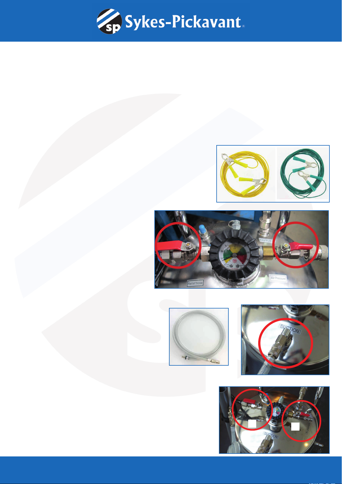
3. DRAINING A TANK
1. Aach the bonding jumpers to the equipment.
Ensure that one of the wires is connected to the vehicle and the other to a
grounding connecon.
2. Before draining begins, remove air from tank by
connecng compressed air and opening the relief valve
and air valve unl gauge reads -20 as shown.
Note: By keeping the air following through the open
valves, this will connue to generate vacuum whilst uid
is being extracted.
3. Take the main hose (and appropriate probe) and connect
them to the equipment under the gauge. (Marked ‘Sucon’)
4. If closed, open the overow valve (Relief hose)
5. If closed, connect the compressed air and open the valve (Air pressure)
NOTE: When the reservoir is full, close the compressed air valve
1.
1. Take the main hose ( + appropriate probe) and connect
them to the equipment under the gauge .(suction)
2. Attach the bonding jumpers to the equipment. Ensure
that one of the wires is connected to the vehicle and the
other to a grounding connection.
3. Open the overflow valve
(Relief hose)
4. Connect the compressed air and
open the valve(Air pressure)
3. 4.
NOTE: When the reservoir is full,
close the compressed air valve.
Always Strictly follow the safety instructions!
QuickFit User Guide
HU46005
A. Draining a Tank
45


