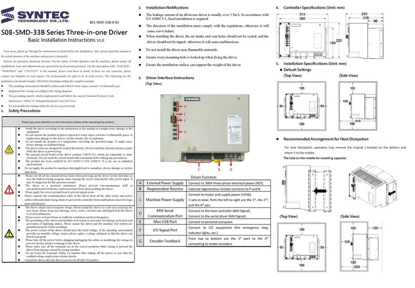
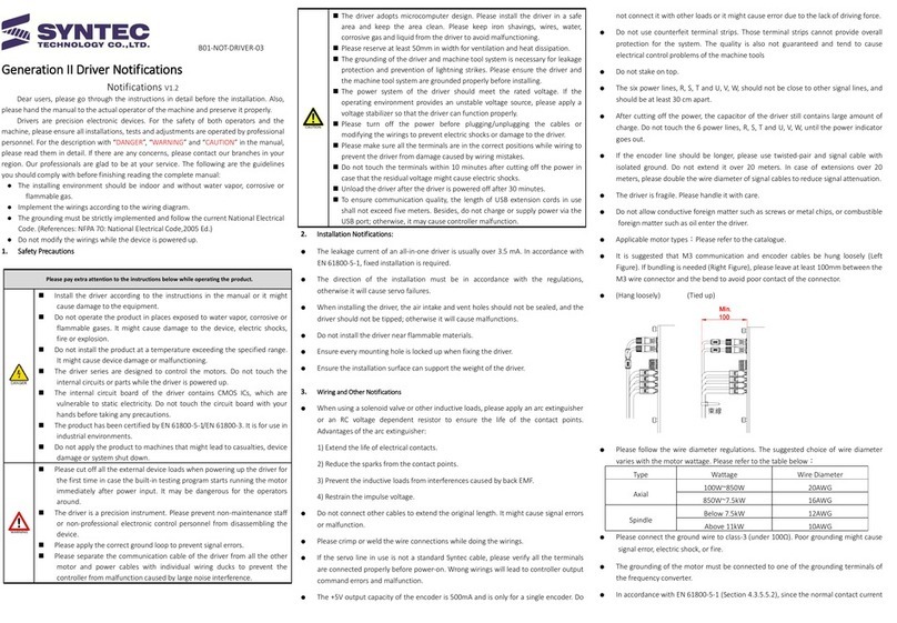
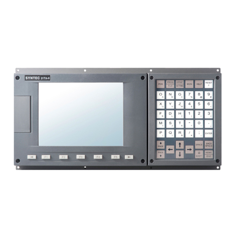
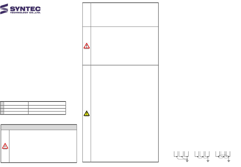
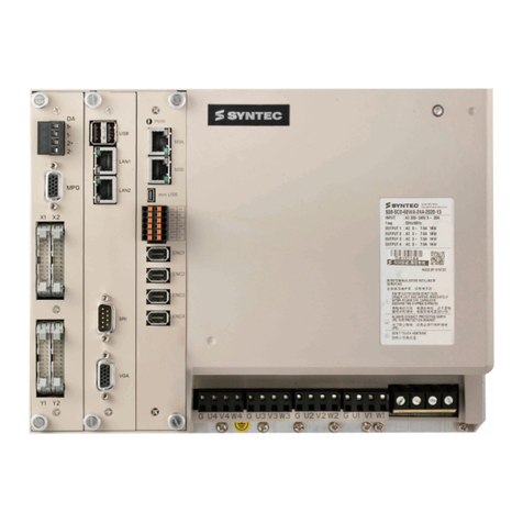
Syntec 22/220 Series Instructions for use

22/220 Series Controller Application Manual
匯出日期:2023-04-25
修改日期:2020-07-16

机床产品/Machine Tool Products
–
22/220 Series Controller Application Manual
–2
•
•
•
•
•
•
•
•
•
•
•
•
•
•
•
•
•
Preface
Controller Descriptions
Hardware List & Descriptions
System Overview
Connection Between Components
Controller Parameter Setting
Driver Parameter Setting
Pitch Error Compensation
Preface
Backlash Compensation
Preface
Quad-Peak Compensation
Preface
Servo Tuning
Serial Parameter Screen Operation
Software Installation、Data Backup/Restore
Check List

机床产品/Machine Tool Products
–
22/220 Series Controller Application Manual
Preface–3
1 Preface
The purpose of this manual is to make users get familiar to the new product, 22/220 series controller, more quickly.
The contents include hardware installation and parameter setting, etc.

机床产品/Machine Tool Products
–
22/220 Series Controller Application Manual
Controller Descriptions–4
2 Controller Descriptions
2.1 Controller Back View
2.2 Controller Description
ADC 24V Power input, DC 24V(1A)
BLAN 1 & 2 10/100M Ethernet interface x2
CKeyboard Keyboard
DUSB USB 2.0 Host x2
EMechatrolink 3 M3 serial communication interface
FOption I/O SRI & RS485

机床产品/Machine Tool Products
–
22/220 Series Controller Application Manual
Controller Descriptions–5
GRIO Port RIO interface, connect to HK-IO and IO module like RIO
module or iTB terminal board.
Pin Define of LAN Pin Define of M3
Pin Define of Option I/O Pin Define of RIO

机床产品/Machine Tool Products
–
22/220 Series Controller Application Manual
Controller Descriptions–6
1.
2.
3.
4.
Pin Define of Option I/O Pin Define of RIO
Precautions:
Syntec standard cable for option I/O only support FC module
because only pin 1 & pin 2 of the cable are functional.
If you want to connect to RS485 interface, you need to customize
the cable to make pin 6 & pin 7 functional.
Please use isolated twisting cable when you customize the cable.
The GND pins on both side must connect to the isolation net of
the cable to avoid RS485 interface burned out.
2.3 Controller Types
No. Type Remark
1 8" Separate
2 8" Standard With keyboard
3 10" Separate
4 10" Full Plane, Separate
5 10" Full Plane, Standard With keyboard
*6 15" Full Plane, Separate 10+8 keys
7 15" Frameless, Separate No function key
*This manual are mainly written with reference to this model.

机床产品/Machine Tool Products
–
22/220 Series Controller Application Manual
Hardware List & Descriptions–7
3 Hardware List & Descriptions
3.1 Hardware List
Item Name Specification
Driver Syntec 4-in-1 Driver SMD-34A Series
Control panel 15" Dedicated control panel for 2nd generation mill
controller
ST4022MS
Keyboard 15" Dedicated keyboard for 2nd generation controller ST4015VK
IO module Terminal board & SRI device(optional)iTB-3232、FC-IO Module
(optional)
MPG Standard remote MPG EHDW Series of Future Life
Technology
3.2 Description of Each Part
3.2.1 Driver
Syntec 4-in-1 Driver(SMD-34A Series)

机床产品/Machine Tool Products
–
22/220 Series Controller Application Manual
Hardware List & Descriptions–8
APower supply Connect to 220V or 380V three-phase alternating
current(RST).
BPower supply for motor Power supply for motor(UVW), the order is 1st/
2nd/3rd/4th from right to left.
CBrake resistor Brake resistor connector(PB)
DM3 serial communication port Connect to M3 controller and other M3 driver.
EMini USB port Connect to personal computer.
FI/O signal port Connect to I/O device.

机床产品/Machine Tool Products
–
22/220 Series Controller Application Manual
Hardware List & Descriptions–9
GEncoder port Connect to motor encoders, the order is1st/2nd/
3rd/4th form top to bottom.
HMPG port(optional)Connect to hand-wheel.
IX1 input port(optional)Same as X1 on the controller, connect to input
terminal board.
JY1 output port(optional)Same as Y1 on the controller, connect to output
terminal board.
MiniUSB Encoder

机床产品/Machine Tool Products
–
22/220 Series Controller Application Manual
Hardware List & Descriptions–10
•
I/O Port
3.2.2 Control Panel
15" Dedicated control panel for 2nd generation mill controller(ST4022MS)
Front View:

机床产品/Machine Tool Products
–
22/220 Series Controller Application Manual
Hardware List & Descriptions–11
•
AKnob Override selection DKey hole Key switch
BButton Cycle start switch EButton Power switch
Ckey Machine function selection FButton Emergency switch
Back View:
AKey hole Key switch
BPower for panel DC 5V power supply for panel, but if HK-IO board exists, the power
supply should not go through this connector.
CPower button Power switch
DEmergency button Emergency switch
EHKIO-RIO interface RIO interface, connect to the controller.
FHKIO-MPG interface MPG interface, same as MPG port on the controller, including 7 input
points(I120~I126).
G7P connector Override selection output signal
HExpanding input point Expanding input point(I118、I119)
ICycle start button Cycle start switch

机床产品/Machine Tool Products
–
22/220 Series Controller Application Manual
Hardware List & Descriptions–12
JHKIO-power for panel &
Expanding output point
DC 24V power supply for panel and Expanding output point
(O120~O124).
HKIO-8P connector I/O Definition of the keys
HKIO-RIO HKIO-MPG

机床产品/Machine Tool Products
–
22/220 Series Controller Application Manual
Hardware List & Descriptions–13
•
Expanding Input Point Expanding Output Point
Only relay switch can be used.
3.2.3 Keyboard
15" Dedicated keyboard for 2nd generation controller(ST4015VK)
AKey Letter key

机床产品/Machine Tool Products
–
22/220 Series Controller Application Manual
Hardware List & Descriptions–14
BKey Number & symbol key
CKey Function key
DKeyboard port USB keyboard interface
3.2.4 IO Module
Terminal Board:iTB-3232
APower supply DC 24V input
BRIO port Connect to RIO port on the controller.
CInput point, I0~I31 32 input points in 8 sets of 8-pin connector, TB1~TB8
DExpanding input
point
Connect to input terminal board for more 16 input points,I32~I47
EOutput point,
O0~O7
8 output points in 4 sets of 4-pin connector, TB9~TB12. Each point can bear 24V/16A.

机床产品/Machine Tool Products
–
22/220 Series Controller Application Manual
Hardware List & Descriptions–15
FOutput point,
O8~O15
8 output points in 4 sets of 4-pin connector, TB13~TB16. Each point can support 24V/
2A.
GOutput point,
O16~O31
16 output points in 4 sets of 8-pin connector, TB17~TB20.Each point can support
24V/0.5A.
TB1-TB8
8 sets of 8-pin connector for I0~I31, the definition of TB1-TB4 are the same as TB5-TB8.
TB9-TB12 TB13-TB16
O0~O7 output points O8~O15 output points

机床产品/Machine Tool Products
–
22/220 Series Controller Application Manual
Hardware List & Descriptions–16
T
B
1
7-
T
B
2
0
O
1
6
~
O
3
1
o
ut
p
ut
p
oi
nt
s
3.2.5 MPG
Standard Remote MPG(EHDW Series of Future Life Technology)
Wiring diagram could be downloaded as follow:MPG wiring.jpg

机床产品/Machine Tool Products
–
22/220 Series Controller Application Manual
System Overview–17
4 System Overview
4.1 SystemArchitecture Diagram

机床产品/Machine Tool Products
–
22/220 Series Controller Application Manual
Connection Between Components–18
•
•
•
•
•
•
5 Connection Between Components
5.1 Controller & Servo Driver
Connect M3 port of controller and M3A or M3B port of servo driver by Syntec standard cable for M3 serial
communication.
Set station ID of servo driver before communication.
There are two setting methods and explained as below.
Knob Dial
Expla
natio
n
Adjust the knob on the upper right corner of the
servo driver.
This type is mostly applied on single-axis driver
or mini multi-axis driver.
Adjust the dial on the front stage board, this type is
mostly applied on multi-axis driver for big power.
Figur
e
Defin
ition
The number that the arrow on the knob points
to is the station ID of the servo driver.
Set Pr21~ of the controller after staion ID of servo driver is ready, Pr21~ is to decide thecorrespondence
between the axis number of the controller and the station ID.
For multi-axis driver, both station ID and sub-station ID have to be set, the format is MMnnn, M is
station ID, n is sub-station ID.
For example, if the station ID of the 4-in-1 driver is 2, the values of Pr21~Pr24 should be 2000、
2001、2002、2003, when sub-station ID starts from 0.

机床产品/Machine Tool Products
–
22/220 Series Controller Application Manual
Connection Between Components–19
•
•
•
•
•
•
•
•
•
•
•
•
•
•
•
•
•
•
•
•
•
•
•
If Pr21=2000, it means X axis of the controller corresponding to the first sub-station of the
driver.
For single-axis driver, the value of Pr21~ is just the same as the station ID of the driver.
For example, Pr21=1 means X axis corresponding to the driver when the station ID is 1.
5.2 Controller & Operation Panel
The 2-head cable is necessary to connect the controller(via RIO port)and the operation panel for 22/220
series controller.
The part NO. of the cable isW01-RIO-EX and shown as below.
The extension cable for RIO is usually needed.
The 1-head side of the cable is used to connect to the RIO port of the controller.
For the 2-head side of the cable, there are marks of P1 & P2, P1 is connecting to the operation panel and P2 is
for IO module, like RIO module or iTB terminal board.
There is an adapter plate named as HK-IO on the back side of the operation panel.
There are two ports on HK-IO, one is RIO port and connects to RIO port of the controller via P1 of the
2-head cable, the other one is MPG port and connects to MPG.
For MPG port, the number of 7 input points are I120~I126.
The power of the panel is inputted through the 8-pin connector on the right side of the HK-IO, the electric
specification is 24V.
Please notice that it's prohibited to input 5V power to the old connector of power on the panel.
When you set Pr5 of the controller as 7, the panel and IO module could be activated via RIO port of the
controller. Notice that the 2-head cable should be connected correctly.
When you set Pr5 of the controller as 11, the panel is activated when the RIO module is deactivated.
It's necessary to connect 2 RIO ports on the controller and HK-IO by P1 of the 2-head cable, or OP-005
alarm will occur.
The alarm won't occur on the same condition when you are using old generation controller.
If nothing will be connected to the RIO port of the controller, please set Pr5 as 100 and disable RIO、
HK、MPG in the I/O mapping table(set as -1), then OP-005 alarm won't happen.
5.3 Controller & Keyboard
Connect the KB port of the controller and the decoding interface on the back side of the keyboard by Syntec
standard keyboard cable.
There is only one USB interface on thededicated keyboard for 2nd generation controller, when there
are 2 slots, function key and PS2 interface, on the traditional keyboard.
For 15" controller, Pr3217=15 when dedicated VK15 keyboard is used(same as the one in this manual).
For 10" controller, Pr3217=13 when dedicated VK10 keyboard is used.
For 8" controller, Pr3217=13 when VK8-900 keyboard is used. This keyboard is not dedicated for 2nd
generation controller, but only one slot should be connected.

机床产品/Machine Tool Products
–
22/220 Series Controller Application Manual
Connection Between Components–20
•
•
•
•
•
•
•
•
•
•
•
5.4 Controller & IO Module
The 2-head cable is necessary to connect the controller(via RIO port)and the IO module for 22/220 series
controller.
The part NO. of the cable isW01-RIO-EX and shown as below.
The extension cable for RIO is usually needed.
The 1-head side of the cable is used to connect to the RIO port of the controller.
For the 2-head side of the cable, there are marks of P1 & P2, P1 is connecting to the operation panel and P2 is
for IO module, like RIO module or iTB terminal board.
There are two types of iTB terminal board, iTB-3232 & iTB-1616, the number means 32 inputs/ 32
outputs and 16 inputs / 16 outputs.
If iTB-3232 is used, you can get 16 more inputs by connecting to additional TB-16IN terminal board.
When you set Pr5 of the controller as 7, the panel and IO module could be activated via RIO port of the
controller. Notice that the 2-head cable should be connected correctly.
5.5 Controller & SRI Device(Optional)
The option I/O port on the controller can connect 1 SRI device like FC module and 1 RS485 interface at the
same time.
Syntec standard cable for option I/O only support FC module because only pin 1 & pin 2 of the cable are
functional.
If you want to connect to RS485 interface, you need to customize the cable to make pin 6 & pin 7 functional.
Other Syntec Controllers manuals
Popular Controllers manuals by other brands

SMA
SMA CLCON-10 installation manual

Metso
Metso Valvcon ADC Series Installation maintenance and operating instructions

GIGAMEDIA
GIGAMEDIA GGM WCAP300 quick guide

Chino
Chino KP 2000 Series instructions

Controlli
Controlli DG501C user guide

Federal Signal Corporation
Federal Signal Corporation 2001-AC Installation and operation manual