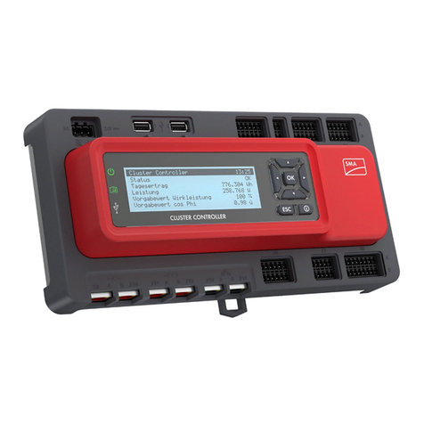
SMA CLCON-10 User manual

InstallationManual
SMA CLUSTER CONTROLLER
ClusterController-IA-en-15 | Version 1.5 ENGLISH

Legal Provisions
The information contained in these documents is property of SMA Solar Technology AG. Any
publication, whether in whole or in part, requires prior written approval by SMA Solar Technology
AG. Internal reproduction used solely for the purpose of product evaluation or other proper use is
allowed and does not require prior approval.
SMA Warranty
You can download the current warranty conditions from the Internet at www.SMA-Solar.com.
Software Licenses
The licenses for the software modules used with this product can be found on the supplied CD.
Trademarks
All trademarks are recognized, even if not explicitly identified as such. A lack of identification does
not mean that a product or symbol is not trademarked.
The BLUETOOTH® word mark and logos are registered trademarks of BluetoothSIG,Inc. and any
use of these marks by SMASolarTechnologyAG is under license.
Modbus® is a registered trademark of Schneider Electric and is licensed by the Modbus
Organization, Inc.
QR Code is a registered trademark of DENSO WAVE INCORPORATED.
Phillips® and Pozidriv® are registered trademarks of Phillips Screw Company.
Torx® is a registered trademark of Acument Global Technologies, Inc.
SMASolarTechnologyAG
Sonnenallee 1
34266 Niestetal
Germany
Tel. +49 561 9522-0
Fax +49 561 9522-100
www.SMA.de
E-mail: [email protected]
© 2004 to 2015SMASolarTechnologyAG. All rights reserved.
Legal Provisions SMA Solar Technology AG
Installation ManualClusterController-IA-en-152

Table of Contents
1 Information on this Document ................................................. 6
1.1 Validity................................................................................................ 6
1.2 Target group....................................................................................... 6
1.3 Additional Information....................................................................... 6
1.4 Symbols .............................................................................................. 6
1.5 Typographies...................................................................................... 7
1.6 Nomenclature..................................................................................... 7
2 Safety......................................................................................... 8
2.1 Intended Use ...................................................................................... 8
2.2 Safety Information.............................................................................. 8
2.3 Supported Products............................................................................ 9
2.4 System Requirements ......................................................................... 10
3 Scope of Delivery...................................................................... 11
4 Product Description................................................................... 12
4.1 Cluster Controller ............................................................................... 12
4.2 Type Label .......................................................................................... 17
4.3 LEDs..................................................................................................... 18
4.4 Display................................................................................................ 19
4.5 Keypad ............................................................................................... 20
5 Mounting ................................................................................... 22
5.1 Requirements for Mounting ............................................................... 22
5.2 Mounting the Cluster Controller........................................................ 23
6 Connection and Commissioning .............................................. 25
6.1 Overview of the Connection Area .................................................... 25
6.2 Functions of the Terminals and Pin Groups ...................................... 26
6.3 Cable Requirements........................................................................... 28
6.4 Performing Pin Coding....................................................................... 29
6.5 Preparing Connection Cables for Connection to Multipole Plugs .. 30
6.6 Connecting the Cluster Controller to the Voltage Supply................ 32
Table of Contents
SMA Solar Technology AG
Installation Manual 3ClusterController-IA-en-15

6.7 Checking and Setting the Cluster Controller System Time............... 35
6.8 Connecting the Cluster Controller to a Speedwire Network .......... 36
6.9 Connecting the Cluster Controller to the LAN.................................. 38
6.10 Connecting USB Data Carriers to the Cluster Controller................. 39
6.11 Connecting Sensors to the Cluster Controller................................... 40
6.11.1 Connecting the Temperature Sensor............................................. 40
6.11.2 Connecting an Irradiation Sensor................................................. 43
6.11.3 Connecting Additional Sensors..................................................... 44
6.12 Connections for Grid Management Services................................... 47
6.12.1 Options for Implementing Grid Management Service Setpoints 47
6.12.2 Digital Setpoint Signal ................................................................... 48
6.12.2.1 Connection Options ................................................................ 48
6.12.2.2 Connecting a Signal Source to a Digital Input for Active
Power Limitation....................................................................... 49
6.12.2.3 Connecting a Signal Source to a Digital Input for Reactive
Power Setpoint......................................................................... 51
6.12.2.4 Digital Signal Setpoint when Using Multiple Cluster
Controllers................................................................................ 53
6.12.3 Analog Setpoint Signal.................................................................. 54
6.12.3.1 Connecting a Signal Source to an Analog Input for Active
Power Limitation....................................................................... 54
6.12.3.2 Connecting a Signal Source to an Analog Input for
Reactive Power Setpoint.......................................................... 55
6.12.3.3 Analog Setpoint Signal when Using Multiple Cluster
Controllers................................................................................ 56
6.12.4 Setpoint via Modbus Client........................................................... 57
6.12.5 Feedback of the Cluster Controller ............................................... 57
6.12.5.1 Feedback Options................................................................... 57
6.12.5.2 Connecting a Remote Terminal for Feedback via Digital
Signal ....................................................................................... 58
6.12.5.3 Connecting a Remote Terminal for Feedback via Analog
Signal ....................................................................................... 59
6.12.5.4 Feedback When Using Multiple Cluster Controllers............. 63
6.13 Checking the Connections via the Display....................................... 64
6.14 Configuring a Static LAN................................................................... 65
6.15 Setting Up a Modbus Data Connection........................................... 65
7 Troubleshooting ........................................................................ 66
Table of Contents SMA Solar Technology AG
Installation ManualClusterController-IA-en-154

7.1 LED States........................................................................................... 66
7.1.1 Operation LEDs.............................................................................. 66
7.1.2 Network Port LEDs ......................................................................... 69
7.2 Errors in the Cluster Controller or the Connected Devices .............. 70
7.3 Resetting the Cluster Controller ......................................................... 74
8 Decommissioning...................................................................... 76
8.1 Disassembling the Cluster Controller ................................................ 76
8.2 Packing the Product for Shipment ..................................................... 76
8.3 Disposing of the Product.................................................................... 77
9 Technical Data........................................................................... 78
10 Accessories ................................................................................ 82
11 Contact....................................................................................... 83
Table of Contents
SMA Solar Technology AG
Installation Manual 5ClusterController-IA-en-15

1 Information on this Document
1.1 Validity
This document is valid for the SMAClusterController (models "CLCON-10" and "CLCON-S-10")
from hardware versionA1 and from firmware version1.03.xx.R.
1.2 Target group
The tasks described in this document must only be performed by qualified persons. Qualified
persons must have the following skills:
• Training in the installation and configuration of IT systems
• Knowledge of how an inverter works and is operated
• Training in how to deal with the dangers and risks associated with installing and using
electrical devices and installations
• Training in the installation and commissioning of electrical devices and installations
• Knowledge of the applicable standards and directives
• Knowledge of and compliance with this document and all safety information
1.3 Additional Information
Links to additional information can be found at www.SMA-Solar.com:
Document title Document type
"SMASPEEDWIRE FIELDBUS" Technical Information
1.4 Symbols
Symbol Explanation
Indicates a hazardous situation which, if not avoided, will result in
death or serious injury
Indicates a hazardous situation which, if not avoided, can result in
death or serious injury
Indicates a hazardous situation which, if not avoided, can result in
minor or moderate injury
Indicates a situation which, if not avoided, can result in property
damage
Information that is important for a specific topic or goal, but is not
safety-relevant
Indicates a requirement for meeting a specific goal
Desired result
A problem that might occur
1 Information on this Document SMA Solar Technology AG
Installation ManualClusterController-IA-en-156

1.5 Typographies
Typography Use Example
bold • Display texts
• Elements on a user interface
• Terminals
• Elements to be selected
• Elements to be entered
• The value can be found in
the field Energy.
• Select Settings.
• Enter 10 in the field
Minutes.
>• Connects several elements to be
selected
• Select Settings > Date.
[Button]
[Key]
• Button or key to be selected or
pressed
• Select [Next].
1.6 Nomenclature
Complete designation Designation in this document
Large-scale PV power plant PV system
PV inverter Inverter
SMAClusterController ClusterController
SMA Energy Meter Energy Meter
1 Information on this Document
SMA Solar Technology AG
Installation Manual 7ClusterController-IA-en-15

2 Safety
2.1 Intended Use
The ClusterController is a device for monitoring and controlling SMAinverters with Speedwire/
Webconnect interfaces in decentralized PV systems and large-scale PV power plants.
The ClusterController is an ITE classA device as per EN55022 and is designed for industrial use.
The product is designed for indoor use only.
Use this product only in accordance with the information provided in the enclosed documentation
and with the locally applicable standards and directives. Any other application may cause
personal injury or property damage.
Alterations to the product, e.g. changes or modifications, are only permitted with the express written
permission of SMA Solar Technology AG. Unauthorized alterations will void guarantee and
warranty claims and in most cases terminate the operating license. SMA Solar Technology AG
shall not be held liable for any damage caused by such changes.
Any use of the product other than that described in the Intended Use section does not qualify as
appropriate.
The enclosed documentation is an integral part of this product. Keep the documentation in a
convenient place for future reference and observe all instructions contained therein.
The type label must remain permanently attached to the product.
2.2 Safety Information
This section contains safety information that must be observed at all times when working on or with
the product.
To prevent personal injury and property damage and to ensure long-term operation of the product,
read this section carefully and observe all safety information at all times.
Danger to life due to electric shock from touching an ungrounded product
Touching an ungrounded product can cause a lethal electric shock.
• Ensure that the product is integrated in the existing overvoltage protection.
• Ground the enclosure of the product.
Damage to the product due to moisture
The product is not splash-proof (IP20). Moisture can penetrate the product and damage it.
• Only use the product in a dry, indoor environment.
2 Safety SMA Solar Technology AG
Installation ManualClusterController-IA-en-158

2.3 Supported Products
SMA Products
Availability of SMA products in your country
Not all SMA products are available in all countries. For information on whether an SMA
product is available in your country, visit the website of your country's SMA subsidiary at
www.SMA-Solar.com or contact your distributor.
The ClusterController can establish a connection to and display data on the following SMA
products that are equipped with Speedwire communication:
Inverters:
• All inverters with integrated or retrofitted Speedwire/Webconnect interface
Information on whether an inverter has an integrated Speedwire/Webconnect interface or can
be retrofitted with a Speedwire/Webconnect interface can be found on the inverter product
page at www.SMA-Solar.com.
Other products:
• SunnyPortal
• SMA Energy Meter
• SMAFuelSaveController
• SMAGridGate of device type "GRIDGATE-20" from firmware version1.0
• SMAPowerPlantController
Products from Other Manufacturers
Sensors:
• Irradiation sensors that can output a current signal in the range from 0mAto20mA
• Temperature sensors with a Pt100 measuring shunt or a Pt1000 measuring shunt
• Other sensors that can output a current signal in the range from 0mAto20mA or a voltage
signal in the range from −10V to+10V
Signal receivers and digital and analog signal sources:
• Signal sources with relay contacts
• Signal sources that provide digital output signals
• Signal sources that can output current signals in the range from 0mA to 20mA
• Signal sources that can output voltage signals in the range from −10V to+10 V
• Signal receivers that can process current signals in the range from 0mA to 20mA
Routers and network switches:
• Routers and network switches for Fast Ethernet with a data transfer rate of at least 100Mbit/s
All network components used must support the IGMP version 1 protocol (IGMPv1).
2 Safety
SMA Solar Technology AG
Installation Manual 9ClusterController-IA-en-15

Power supply units:
In addition to the top-hat rail power supply unit offered as an accessory (see Section10, page82
), the ClusterController supports power supply units with the following properties:
• Maximum output current including short circuit: 8A
• Maximum output apparent power: 100VA
• DC output voltage: 24V
• Nominal current: minimum 1.8A
2.4 System Requirements
Supported web browsers:
☐ MicrosoftInternetExplorer from version8
☐ MozillaFirefox from version3.6
Recommended display resolution:
☐ Minimum 1,024pixelsx768pixels
2 Safety SMA Solar Technology AG
Installation ManualClusterController-IA-en-1510

3 Scope of Delivery
Check the scope of delivery for completeness and any externally visible damage. Contact your
distributor if the scope of delivery is incomplete or damaged.
Figure 1: Components included in the scope of delivery
Position Quantity Designation
A 1 ClusterController
B 1 Three-pole plug
C 1 Two-pole plug*
D 2 Five-pole plug
E 8 Six-pole plug**
F 2 Eight-pole plug
G 2 Coding element
H 20 Cable tie with caption field
I 8 Shield clamp with ring terminal lug
K 1 Ring terminal lug
L 1 Fastening screw
M 2 Washer
N 1 Tooth lock washer
O 1 Split lock washer
P 1 CD with product documentation
Q 1 Quick reference guide for commissioning and supplementary sheet
for noting down connected devices
* Reserved for future applications. Keep the plug in a safe place.
** Two of the eight plugs are reserved for future applications. Keep the twoplugs in a safe place.
3 Scope of Delivery
SMA Solar Technology AG
Installation Manual 11ClusterController-IA-en-15

4 Product Description
4.1 ClusterController
The ClusterController is a device for monitoring and controlling SMAinverters with Speedwire/
Webconnect interfaces in decentralized PV systems and large-scale PV power plants.
The ClusterController primarily performs the following tasks:
• Set-up of the Speedwire network
• Reading out, provision and administration of PV system data
• Configuring device parameters
• Feedback on current total active power of the system
• Implementation and feedback of grid operator setpoints for active power limitation and
reactive power operation under grid management services
• Implementation and feedback of setpoints for active power limitation when PV electricity is
directly marketed
• Sending e-mail alarms in the event of critical system statuses
• Sending the system data to an FTP server and/or the SunnyPortal Internet portal
• Performing updates for the ClusterController and the inverters
Figure 2: Design of the ClusterController
Position Designation
A LEDs
B Connection areas
C Keypad
D Display
Reading out, provision and administration of PV system data
The ClusterController is the central communication unit for the system and continuously reads out
the data of the devices in the system (e.g. inverters, sensors). The ClusterController then makes this
system data available via the display, user interface and Modbus data interface. In addition, the PV
system data can be displayed, evaluated and managed using Sunny Portal.
4 Product Description SMA Solar Technology AG
Installation ManualClusterController-IA-en-1512

Configuring device parameters
You can configure specific parameters of individual devices or entire device classes via the user
interface of the ClusterController. You must be logged into the user group Installer on the
ClusterController. The device parameters that can be configured, if any, depend on the device and
the rights of the user group. You may only change grid-sensitive device parameters
(SMAGridGuard parameters) with the approval of the grid operator and using your personal
SMAGridGuard code.
Sending e-mail alarms in the event of critical system statuses
You have the option of receiving prompt information on critical system statuses via e-mail. The
ClusterController automatically sends a notification if alarm-related events occur in the system.
Feedback on current total active power of the system
You have the option of being informed of the total active power currently generated by the system
via an analog current output signal.
Implementation and feedback of grid operator setpoints for active power
limitation and reactive power operation under grid management services
With the ClusterController, as part of grid management services you can implement different grid
operator setpoints for active power limitation and reactive power operation of your system. The
ClusterController can implement the setpoints using open-loop control or closed-loop control.
For ClusterController systems without self-consumption and with direct limitation of active power
feed-in, the operating mode Open-loop control is used. In this operating mode, the
ClusterController can receive the setpoints either in the form of digital or analog signals, or via
Modbus. The different types of signal source can be combined so that, for example, the setpoints
for the active power limitation are received as digital signals and the reactive power setpoints are
received as analog signals: For ClusterController systems with self-consumption, the operating
mode Closed-loop control is used. In this operating mode, you can regulate the active power fed
in by the system at the grid-connection point and limit it e.g. to a fixed percentage value. In
agreement with your grid operator, you can use the user interface of the ClusterController to
configure which setpoints of the ClusterController are to be transmitted to the connected inverters
depending on the respective signal. In addition, you can use a digital response contact or an
analog current output signal to inform the grid operator of the setpoints (if any) for active power
limitation and reactive power operation that are currently being used in the system.
Implementation and feedback of setpoints for active power limitation when PV
electricity is directly marketed
The PV current generated by your system can be directly marketed. The ClusterController can
receive setpoints for active power limitation from the direct marketer as digital or analog signals or
via Modbus. The "CLCON-S-10" model provides a Modbus register for sending setpoints via
Modbus. The model "CLCON-10" provides two Modbus registers.
The ClusterController can provide feedback about the current feed-in power of the system to the
direct marketer via digital or analog signals. To avoid conflicts when different setpoints are used by
the grid operator and the direct marketer, the ClusterController always implements the setpoint that
more strongly limits the active power of the system.
4 Product Description
SMA Solar Technology AG
Installation Manual 13ClusterController-IA-en-15

Sending the system data to an FTP server and/or the SunnyPortal Internet
portal
The ClusterController can automatically send the system data that has been read out to an
arbitrary FTP server and/or the SunnyPortal Internet portal via the Internet. The ClusterController
establishes the connection to the FTP server and/or SunnyPortal e.g. via a router.
Performing updates for the ClusterController and the inverters
You have the option of performing updates for the Cluster Controller and the inverters in the system.
You can perform the updates automatically or manually. The update source can be the
SMAUpdate Portal or a USB data carrier with update files downloaded from the Internet.
Alternatively, you can also upload the update files directly from the computer via the user interface
of the ClusterController.
Figure 3: Decentralized large-scale PV power plant with ClusterController and implementation of grid operator
setpoints via open-loop control (example)
Position Designation
A PV Modules
B Module temperature sensor
C Inverter
D Outside temperature sensor
4 Product Description SMA Solar Technology AG
Installation ManualClusterController-IA-en-1514

Position Designation
E Irradiation sensor
F ClusterController
G SunnyPortal
H Router
I Ripple control receiver or remote terminal unit
K Grid station
L Control room
M Grid control room
N Utility grid
4 Product Description
SMA Solar Technology AG
Installation Manual 15ClusterController-IA-en-15

Figure 4: Decentralized large-scale PV power plant with ClusterController and implementation of grid operator
setpoints via closed-loop control (example)
Position Designation
A PV Modules
B Module temperature sensor
C Inverter
D Outside temperature sensor
E Irradiation sensor
F ClusterController
G Industrial load
H SunnyPortal
I Router
K Ripple control receiver or remote terminal unit
4 Product Description SMA Solar Technology AG
Installation ManualClusterController-IA-en-1516

Position Designation
L Energy meter
M Control room
N Grid control room
O Grid station
P Utility grid
4.2 Type Label
The type label clearly identifies the product. The type label can be found on the back of the
enclosure. You can read off the following data from the type label:
• Device type (Type)
• Serial Number
• Hardware version (Version)
• Model
• Device-specific characteristics
You will require the information on the type label to use the product safely and when seeking
customer support from Service (see Section11 "Contact", page83).
Symbols on the Type Label
Symbol Designation Explanation
C-Tick The product complies with the require-
ments of the applicable Australian
EMC standards.
CANICES-3(A)/
NMB-3(A)
IC marking The product complies with the require-
ments of the applicable Canadian
EMC standards.
Indoors The product is only suitable for indoor
installation.
FCC designation The product complies with the require-
ments of the applicable FCC stan-
dards.
CE marking The product complies with the require-
ments of the applicable EU directives.
4 Product Description
SMA Solar Technology AG
Installation Manual 17ClusterController-IA-en-15

Symbol Designation Explanation
WEEE designation Do not dispose of the product together
with household waste but in accor-
dance with the locally applicable dis-
posal regulations for electronic waste.
Data matrix code 2Dcode for device-specific character-
istics
4.3 LEDs
Operation LEDs
LED Designation Explanation
Power LED Shows whether the ClusterController is starting or is in op-
eration (see Section7.1 "LED States", page66)
Status LED Shows the status of the ClusterController and the con-
nected devices as well as the communication status of the
system and the status of the grid management services
(see Section7.1 "LED States", page66)
Data carrier status
LED
Shows the status of the connected USB data carrier (see
Section7.1 "LED States", page66)
Network Port LEDs
Colors and functionality of the network port LEDs are not standardized
The colors and functionalities of the network port LEDs are not standardized. The colors used
by SMA for the link/activity LED and the speed LED as well as the corresponding
functionalities can deviate in products supplied by third-party manufacturers.
4 Product Description SMA Solar Technology AG
Installation ManualClusterController-IA-en-1518

Figure 5: Network port LEDs
Position Designation Color Explanation
A Link/activity LED Green Shows the status and the activity of the network
connection (see Section7.1.2 "Network Port
LEDs", page69)
B Speed LED Yellow Shows the network connection speed (see Sec-
tion7.1.2 "Network Port LEDs", page69)
4.4 Display
The display shows information on the ClusterController and the connected devices as well as the
system status and the system configuration. The display contrast can be configured. The display
languages are "German" and "English". You can change the display language via the
ClusterController user interface.
Figure 6: ClusterController display (example)
Position Designation Explanation
A Title line Displays the title of the display view
The system time is always displayed.
B Data lines Displays text and numeric values
The numeric values for measurement or yield data are dis-
played with units.
Overview of the Display Views
Display view Explanation
Start view Displayed when the ClusterController starts up; includes the current
firmware version of the ClusterController
4 Product Description
SMA Solar Technology AG
Installation Manual 19ClusterController-IA-en-15

Display view Explanation
System overview Displays the system status, the current daily yield, the nominal sys-
tem power and the current setpoints for active power and reactive
power
If no button on the keypad is pressed within five minutes, the Clus-
terController switches to the display view System overview.
Yield data Displays the yield data of the system
System status Displays the current system status
The number of inverters detected by the ClusterController and the
status of the inverters is displayed here.
ClusterController Displays the status and device information of the ClusterController
When a USB data carrier is inserted into USB port1, information on
the current memory usage of the USB data carrier will be displayed.
SunnyPortal settings Displays the configured upload frequency and the date of the last
successful data upload to SunnyPortal
Analog inputs Displays the analog inputs with the current level value and unit
Digital inputs Displays the digital inputs in binary form
The digital inputs are summarized in two groups here.
Meteorology Displays the measured values of the connected irradiation sensor
and the connected temperature sensors
Active power limitation Displays the current setpoint for active power limitation with the set-
point size and the date of the last configuration change
Reactive power setpoint Displays the current reactive power setpoint and the date of the last
configuration change
Grid management services Displays the setpoint type and the signal sources selected via the
ClusterController user interface for the grid management services
External communication Displays the settings for the LAN
Speedwire Displays the settings for the Speedwire network
Modbus settings Displays the Modbus settings with the activated network protocols
and the corresponding network ports
Settings Enables the display contrast to be changed and the ClusterCon-
troller to be partially or fully reset (see Section7.3, page74)
4.5 Keypad
Designation Explanation
Any button Activates the display illumination
Arrow buttons (◂▸▴▾) Changes display views and selects specific display lines
4 Product Description SMA Solar Technology AG
Installation ManualClusterController-IA-en-1520
Other manuals for CLCON-10
1
This manual suits for next models
1
Table of contents
Other SMA Controllers manuals
Popular Controllers manuals by other brands

Apollo
Apollo AIM-4SL Hardware manual

SMC Networks
SMC Networks PFCA7 Series Operation manual

IBT
IBT SWITCH..IT installation guide

PIETRO FIORENTINI
PIETRO FIORENTINI NORVAL Installation, commisioning and maintenance instructions

Barco
Barco MXRT-1450 user guide

Emerson
Emerson Fisher 67D Series installation guide

Midian Electronics
Midian Electronics TRC-1 manual

DPCAV
DPCAV ShutterBug Pro instructions

Pentair
Pentair AUTOTROL Performa 263 user guide

Harman
Harman AMX NETLINX NX-1200 quick start guide

Zonefirst
Zonefirst Uni-Zone H32P Series Installation and operating instructions

Bosch
Bosch LTC 8600 instruction manual