P/N 03723018 Rev B Page 1
DLC2
Disposable Lens Cu
User Instructions
Intended Use
The MAXAIR DLC2 is to be donned with a MAXAIR CAPR®
Helmet and a MAXAIR Filter Cartridge.
CAPR DLC2 Systems lter aerosolized and droplet particulates.
DLC2s are designed for single use applications.
DLC2
2380-02
03731013
1. 2081-03 Helmet with
2051-07 SnapOn Cage
removed, 2071-08 Liner, and
2590-05 Power Cord
2. 2167-10 Filter Cartridge
3. 2061-08 Filter Cover
Cap
4. 2500-36TSC Battery* 5. 2000-76 Battery Belt
6. 2600-02 Battery Charger 7. 2380-02 DLC2
Materials
DLC2 Lens is Polycarbonate
DLC2 Cu Blue White Barrier
Alternate Batteries include the 2500-37TSC
5
6
4
32
7
1
Standard CA-DLC-CAPR-36 System1with DLC2
MAXAIR Recommended System Temperature Limits:
Use/Handling: 0oC to 540C at a maximum 80% Relative Humidity.
Charging: 0oC to 450C at a maximum 80% Relative Humidity.
Storage: 0oC to 350C at a maximum 80% Relative Humidity.
All MAXAIR Systems, components, and disposables are latex free.
Regulatory
NIOSH
Specications
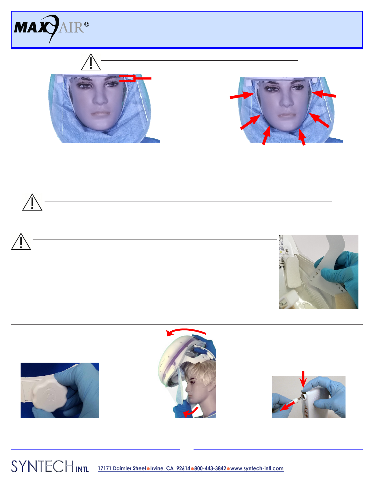
WARNING
Failure to follow User Instructions P/N 03521015 and the instructions
contained herein may be hazardous to the user’s health.
Use only if package is received unopened and contents are
undamaged. If damage is noted, contact the shipper for replacement
or repair.
Prior to using any MAXAIR® System or component, be sure to be
familiar with the system’s NIOSH approved conguration.
DO NOT use if any component is damaged. If any components are
damaged or contaminated and therefore unt for safe and eective
use, they should be replaced immediately.
Only trained and experienced personnel who have read and
understand the User Instructions should use MAXAIR Products.
The institution using this product in any application is responsible
for determining the appropriateness of this equipment relative to
regulatory requirements. Bio-Medical Devices Intl, Inc. does not
recommend the appropriate systems for a particular institution or
facility.
Use only MAXAIR Systems/ NIOSH approved compatible
components.
NOT for use in atmospheres immediately dangerous to life or health
(IDLH), and atmospheres containing less than 19.5% oxygen, or
more than 25% oxygen.
Flammability Level I: fabric may burn if exposed to open ame.
Follow current local regulations governing biohazard waste to safely
dispose of single use MAXAIR Products.
If you need more information, contact your BMDI Sales
Representative, or call BMDI customer service at 1-800-443-3842.
!
CAUTION
Before use, thoroughly read MAXAIR CAPR P/N 03521015 User Instruction (received with all CAPR Helmets and
available at www.maxair-systems.com.
!
Warning, Caution, or Note
Catalog Number NIOSH Number
!
Symbol Denitions
REF P/N
REF
P/N