FHW12, FHW22, FHW32, FHW33
10
General recommendations
Carefully read this instruction manual before
installation and use of the FHW unit. Keep these
instructions in a safe place for future reference.
Area of use (application area)
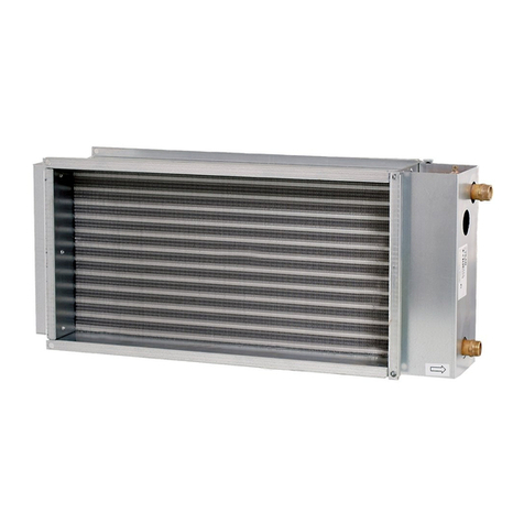
FHW is a fanheater with water connection used for
heating industrial plants, warehouses, shops etc.
The unit consists of the followning:
Casing
Corrosion-proof, hot rolled galvanized and powder
coated casing. Colour code: RAL9016, NCS 0500.
Top/bottom lids are easy to open and are fitted
with hinges for easy and simple installation
and maintenance.
Fan unit
Fully enclosed single-phase 230V, 50Hz, intergrated
motor with an axial fan. Protection class IP44.
Maximum surrounding temperature: +40°C.
The fan motor is prepared for multiple fan
speed control. For external rpm control, see
wiring diagrams. The motor is equipped with
an automatically returning thermocontact which
is connected to the terminal blocks.
Water heating coil
Heating coil with aluminium fins (fin distance 2 mm)
and copper tubes. Smooth pipe connections for
soldering or clamping ring coupling. In standard
designs, FHW is intended for hot water up +90°C.
FHW is also available in special designs for water
temperatures up to +130°C. The heating coils
are pressure tested for 30 bar. Maximum working
pressure is 16 bar.
All models are delivered with individually adjustable
louvres for controlling the air current in one direction.
Louvres of anodized aluminium.
Mounting
FHW is delivered with casing, fan, heating coil
and air director as a standard. Mounting fixtures,
consisting of two brackets, are orded separately.
FHW can be mounted on the wall for horisontal
air distribution or on the ceiling for vertical air
distribution. FHW can be mounted with the pipes
either to the left or to the right. They must however,
not be connected pointing upwards or downwards.
FHW without accessories
Measure and mark the drilling holes on the wall or
on the celing. Use a suitable screwing device to fit
the fixtures. Use the indcluded set of screws to fit
the fixtures on to the FHW.
FHW with mixing cabinet FHWMC and filter
section FHWF
The mixing cabinet and/or the filter section are
mounted together with the FHW unit with screws or
guides.
The damper motor is fitted to the damper shaft.
If required, the damper motor can be mounted on
the opposite side of the mixing cabinet by loosening
the screws holding the shaft. These screws can be
reached from the inside of the mixing cabinet.
When the filter section is used with the FHW
unit only and mounted on to the wall, use the return
air intake FHWD. The return air intake is mounted
together with the FHW unit with screws or guides.
The return air intake is mounted on to the wall with a
suitable screwing device.
When the mixing cabinet is fitted with a return air
duct, remove the three screws holding the circular
protection grill and install a circular duct on to the
mixing cabinet.
The construction should bee stabilized by
pendlums, rods, straps or similar from the wall or the
ceiling. Check the connections between the units, in
case of air leakage use a suitable strip seal.
GB
