System air TG-KH/PT1000 User manual

Installation instruction EN
Pre-heater for Topvex

Table of contents
1 Introduction .......................................................... 1
1.1 Product description ......................................1
1.2 Intended use ..............................................1
1.3 Product overview CB....................................1
1.4 Product overview RB....................................1
1.5 Product overview TG-KH/PT1000 ...................2
2 Safety .................................................................2
2.1 Safety definitions......................................... 2
3 Installation............................................................2
3.1 To do before installation of the product .............2
3.2 To install the pre-heater ................................2
3.3 To use the manual overheat reset ................... 3
4 Wiring diagram CU27 ............................................. 4
5 Wiring diagram CU283............................................5
6 For Topvex with Access control system from sw 4.
X.......................................................................6
6.1 To set up the pre-heating function ................... 6
6.2 To activate the pre-heating function ................. 6
6.3 To configure the pre-heater............................6
6.4 To allocate the pre-heater.............................. 7
6.5 Operation settings .......................................7
6.6 To save commissioning settings...................... 8
7 For Topvex with control system sw 3.X .......................9
7.1 To set up pre-heating function ........................9

1 Introduction
1.1 Product description
The product is a pre-heater and duct sensor which is in-
tended for use together with Topvex counterflow units.
1.2 Intended use
The product is used for compensation of heating capacity
and protection against icing in the heat exchanger.
The product is intended for installation together with Topvex
air handling units in ventilation systems with circular or rec-
tangular ducts.
The maximum ambient temperature for the pre-heater is 30
° C.
The maximum temperature of the output air is 50 °C.
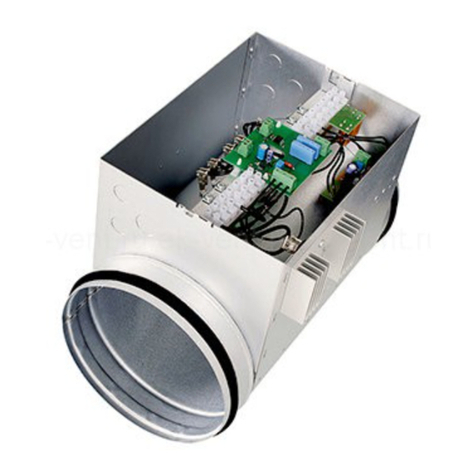
1.3 Product overview CB
3
2
4
1
1. Heating rods
2. Name plate
3. Overheat protection reset button
4. Duct joints with rubber rings
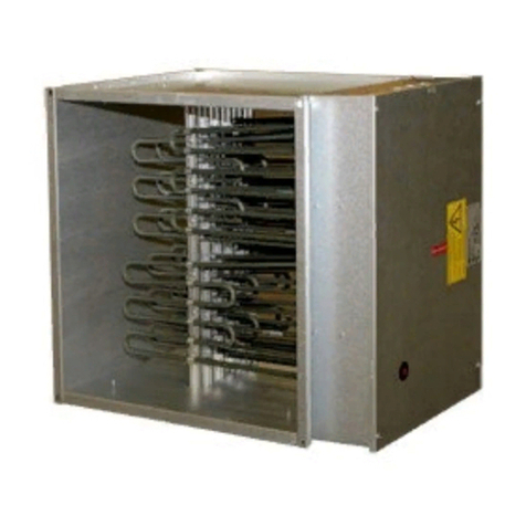
1.4 Product overview RB
5
3
2
1
4
6
1. Electric cabinet
2. Air flow direction arrow
3. Name plate
4. Manual overheat protection reset button
5. Casing
1

1.5 Product overview TG-KH/PT1000
1
2
3
1. Cable gland
2. Sensor probe
3. Mounting bracket
2 Safety
Warning
Set the installed safety switch in the OFF
position before you do the maintenance
unless the instructions tell you differently.
Make sure that the safety switch is not
accidentally set in the ON position.
The heater is S-marked, CE-marked, EMC-marked and
designed in accordance with SEMKO 111 FA 1982 / EN
61000-6-2.
2.1 Safety definitions
Warnings, cautions and notes are used to point out specially
important parts of the manual.
Warning
If you do not obey these instructions,
there is a risk of death or injury.
Caution
If you do not obey these instructions,
there is a risk of damage to the product,
other materials or the adjacent area.
Note:
Information that is necessary in a given situation.
3 Installation
3.1 To do before installation of
the product
• Make sure that the pre-heater is connected to the power
supply with a fixed round cable and that all cable glands
are tight against the cables to prevent leaks.
• Make sure that the airflow through the heater cannot be
lower than 1,5 m/s when the pre-heater is in operation.
• Make sure that the air is filtered to make sure there is no
contamination of the airflow sensor.
• Make sure that there is enough room for installation, re-
placement and inspection in the installation location.
3.2 To install the pre-heater
Warning
Minimum distance from the heater to
combustible material must be 30 mm.
Warning
Make sure that it is not possible to touch
the heating element when the product is
in operation.
2

1Install the pre-heater in the duct with a minimum of 2 x
the duct diameter from a duct bend, filter unit, or other
objects that can cause turbulence in the airflow.
For products with circular duct connections, do these
steps:
a. Put the duct on the duct joint of duct heater. Pull the
duct over the rubber rings on the duct joint on duct
heater.
b. Use self drilling screws to attach the duct to the duct
joint.
For products with rectangular duct connections, do these
steps:
a. Install the pre-heater on the duct using guide rails.
Guide rails are not supplied by Systemair.
b. Put fireproof insulation on the pre-heater in accord-
ance with local regulations for ventilation ducts.
2Install the supplied duct sensor (1) in the duct.
a. Use a drill to make a hole for the supplied sensor in
the outdoor air duct.
b. Make sure that the distance between the hole and
the pre-heater (2) is minimum 1.5 m.
c. Put the sensor in the hole, adjust the length and at-
tach the sensor with the supplied screws.
2
1
3.3 To use the manual overheat
reset
Warning
Do not touch the heater, there is a risk of
injury.
The duct heater is equipped with manual overheating reset.
The overheat protection is designed to prevent overheating
when the airflow is too low, or if there is a fault in the system.
If the manual overheat protection is released, do these steps:
1Turn off the power supply and wait until the heater is cool.
2Investigate the reason for the released overheat
protection.
3When the problem has been removed, push the over-
heat protection reset button, refer to 1.3 Product over-
view CB and 1.4 Product overview RB.
3

4 Wiring diagram CU27
0V 9
10
11
12
AO4
REF
DI6
REF
UI4
T74
T27T84
PE
L3
L2
L1
PE
L3
L2
L1
N
400V 3N~
21
3
Wiring diagram for CU27 (1), CB (2). Outdoor air sensor (3)
0V G0
Y
1
2
AO4
REF
DI6
REF
UI4
T74
T27T84
PE
L3
L2
L1
7
8
PE
L3
L2
L1
N
400V 3N~
1 2
3
Wiring diagram for CU27 (1), RB (2). Outdoor air sensor (3)
4

5 Wiring diagram CU283
B60
A61
N62
E63
BU B50
OR A51
GN N52
BN
BU
G
G0
90
A01
DI1
AI1
8
9
10
11
12
13
14
91
4
71
30
31
PE
L3
L2
L1
N
PE
L3
L2
L1
N
400V 3N~
4
321
Wiring diagram for control unit (1), expansion module CEM15 (2) and CB pre-heater (3). Outdoor air sensor (4)
B60
A61
N62
E63
BU B50
BU
OR A51
GN N52
BN G
G0
4
71
90
AO1
DI1
AI1
91
30
31
1
2
3
4
G0
Y
PE
L3
L2
L1
PE
L3
L2
L1
7
8
N
400V 3N~
4
321
Wiring diagram for control unit (1), expansion module CEM15 (2) and RB pre-heater (3). Outdoor air sensor (4)
5

6 For Topvex with Access
control system from sw 4.
X
6.1 To set up the pre-heating function
Log in with service mode using password 0612.
Service
0612
Login
6.2 To activate the pre-heating function
Select Yes as Pre-heater in the list of available functions in
the Configuration > Functions > Function activation menu.
Configuration > Functions > Function activation 2023-11-20
Preheater Yes
6.3 To configure the pre-heater
Configure the preheater and its running mode in the Configu-
ration > Functions > Preheater menu.
Select When defrosting to maintain supply air temperature at
desired level only during by-pass defrosting (Pressure
monitoring).
Select Unit running if preheater is used to prevent icing in the
exchanger or to support section defrosting or heating ca-
pacity in very cold climates.
Configuration > Functions > Preheater 2023-11-20
Preheater function Preheater
Type of preheater Electric
Preheater temperature sensor Preheater temperature
Start/Stop function When defrosting, Unit running
Type of feedback Alarm
6

6.4 To allocate the pre-heater
Configuration > I/O allocation settings
Select I/O placement for the connected temperature sensor
and control signals to and from the electric heater in the Con-
figuration > I/O allocation settings submenus.
Do not use the same in- or output for several functions.
Configuration > I/O allocation settings > Analog inputs 2023-11-20
Analog inputs Device Position
Intake air temperature Controller AI4
Preheater temperature PDT2 UI1
Configuration > I/O allocation settings > Digital inputs 2023-11-20
Digital inputs Device Position
Feedback preheater Controller DI6
Configuration > ... > Digital inputs> Feedback preheater 2023-11-20
Name Feedback preheater
Original name Feedback preheater
Contact function Normally closed
Configuration > I/O allocation settings > Analog outputs 2023-11-20
Analog outputs Device Position
Preheater Controller AO4
6.5 Operation settings
Data & Settings > Temperature control > Preheater
Adjust the pre-heater temperature set point in the Data & Settings > Temperature control > Preheater menu
When defrosting:
To maintain a supply temperature during by-pass defrosting, the pre-heater need to compensate for the missing heating ca-
pacity. For example, if the correct supply air temperature is 22 °C, but the heating capacity is only 10 °K, the pre-heater set-
point need to be 12 °C.
Unit running:
Example A: To prevent any ice build-up in the exchanger the pre-heater setpoint need to be 0 °C.
Example B: In very cold climates the pre-heater setpoint need to equal the outdoor temperature used for dimensioning the air
handling unit’s heating capacity. For example, if the unit is dimensioned for outdoor temperatures down to -18 °C but outdoor
temperatures in the location is lower, the pre-heater setpoint need to be -18 °C.
7

Data & Settings > Temperature control > Preheater 2023-11-20
Setpoint preheater -18 °C
6.6 To save commissioning settings
When the installation is complete and all functions are tested, Systemair recommends to save a local backup of the current
configuration in the control unit.
Select Yes on Save commissioning settings in Configuration > System settings > Save and restore settings.
Configuration > System settings > Save and restore settings 2023-11-20
Save commissioning settings Yes
8

7 For Topvex with control system sw 3.X
1Reset the CEM15 by pressing the reset button while the
CEM15 is powered.
2Connect a E3-DSP control panel
3On first start up the controller will start a program for
downloading an application to the main memory.
4The start screen is displayed.
→Application
System
Communication
Time/Date
Input/Output
Use the up and down arrows to move the cursor to Application and press the
right arrow to view available applications.
→Expansion unit 1
Expansion unit 2
Expansion unit 5
Expansion unit 6
Move the cursor to Expansion unit 1 and press the right arrow to select.
Title:
Expansion unit 1
Activate? No
Press OK and change Activate to Yes. Press OK.
The most recently loaded application will be entered into memory. This will
take approximately 30 seconds. The application start screen is displayed.
7.1 To set up pre-heating function
Function with expansion unit. Log on with admin rights, 3333.
Main menu item Sub-menu item 1 Sub-menu item 2 Explanations
* Access rights * Log on Log on
Enter password xxxx Actual
level: None
Log on to service level by entering a 4-digit code. After
reaching the desired level go back with “LEFT” arrow
(press 2 times) on the control panel.
Standard code from factory to enter service level is
2222. Back to operator level: 1111. To enter Admin lev-
el code: 3333.
→Configuration →Communication Function port2 Exp and ext
display
→Corrigo E15
→Input/Output →AI AI3:
Extra unit temp Raw value: NaN
Compensation: 0.0 °C
→AI exp1 AI1 Exp1:
Sign: Outd temp Raw value: 0.0
Compensation: 0.0 °C
9

→DI exp 1 DI1 Exp1:
NO/NC: NC Signal:
Ext alarm1 Status:Off
Overheat pre-heater is presented in the display when
the alarm is active.
→AO exp1 AO1 Exp1:
Sign: Extra unit Auto
Value: 0,0 V
Control signal for heater 0-10V
→DO exp1 DO1 Exp1:
Sign: ExtraUnitActi Auto
Status: Off
Activated during defrosting sequence.
→Extra control unit Mode extra unit Run if
defrosting
Activated during defrosting sequence.
See Example 1
Mode extra unit Run if units
us running
Activated during normal run.
See Example 2
Option: Running if unit is running is to avoid defrosting
if unbalanced airflow is not permitted.
Control mode extra unit
Heating
→Settings →Control extra unit Control extra unit P-band:
33.0 °C
I-time: 100.0 s
Set P-band and I-time for Control extra unit.
→Temperature Extra unit Actual: NaN
°C Setp: 18.0 °C
Set the pre-heater temperature
Example 1
Run if defrosting. If pre-heater is used in order to maintain supply temperature at correct level.
For example, correct supply temperature is +20 °C, the outside air is -4 °C and the heater has an capacity of 10 °C. This is
enough during normal operation on these units but during bypass defrosting the heater needs a capacity of 24 K. This is a de-
ficiency by 14 K.
In this example a set point for the pre-heater needs to be +10 °. Set point must be chosen according to heat capacity and
airflow.
Example 2
Run if units is running. In this case you need to have a set point at 0 °C.
Pre-heater will be active below 0 °C during normal operation. To use this option configuration must be changed. Same extra
sensor as above is used.
It can also be used for a unit in a very cold location when the heating capacity is not enough. For example -30 °C. Set point
depending of heat capacity and airflow. In this case a set point can be, for example -18 °C.
10

11

Document in original language 2023-11-20
455029 - 003
© Copyright Systemair AB
All rights reserved
EOE
Systemair AB reserves the rights to alter their products without notice. This also applies to products already ordered, as
long as it does not affect the previously agreed specifications.
Systemair Sverige AB
Industrivägen 3
SE-739 30 Skinnskatteberg
+46 222 440 00
mailbox@systemair.com
www.systemair.com
last page
Table of contents
Other System air Heater manuals

System air
System air ZRS User manual

System air
System air PTC - DN125 User manual
System air
System air VBR Install guide

System air
System air FHW12 User manual
System air
System air CB Series Install guide

System air
System air Topvex RB-CEM15 User manual
System air
System air CBMT/Q Series User manual
System air
System air RB Install guide
System air
System air CBMB Series Install guide