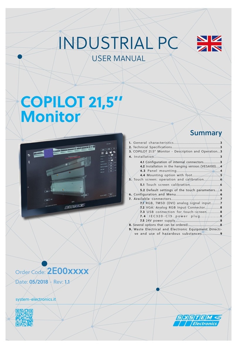
SYSTEM Electronics COPILOT Monitor 15.6" User manual

system-electronics.it
USER MANUAL
COPILOT 15.6’’
Monitor
INDUSTRIAL PC
Order:
2E00xxxx
Date: 05/2020 - Rev: 1.1
SUMMARY
1. General characteristics.............................................3
2. Technical specifications..................................................3
3.Installallation..............................................3
3.1 Power connection......................3
3.2 Connector Layout.....................4
4. Description and operation..........................................4
4.1 Hanging version installation (VESA100)..........4
4.2 Panel Mounting........................................5
4.3 Foot mounting option...................5
5. Touch screen: Operation and calibration........7
6. Connectors available...........................................7
7. Directive for electrical and electronic equipment’s
waste and use of hazardous substances................8

pag.
2
Industrial pc - Monitor COPILOT 15,6"
Order. 2E00xxxxMay 2020 - Rev. 1.1
Revision History Pages
Rev. 1.0 Drafting 8
Rev. 1.1 Updating 8
SYSTEM Ceramics S.p.A - Div. Electronics
via Ghiarola Vecchia, 73
41042 Fiorano (MO) - Italy
tel. 0536/836111 - fax 0536/830901
www.system-group.it
e-mail: info.electronics@systemceramics.com
This product meets the EMC protection re-
quirements of Directive 2014/30/ EC (ex
89/336 EEC) and subsequent amendments.
SYSTEM Ceramics S.p.A - Div. Electronics reserves
the right to make changes of any kind to the technical
specications at any time and without notice. The in-
formation contained in this documentation is believed
to be correct and reliable. The reproduction, even if
partial, of the content of this catalog, is allowed only
with the authorization of SYSTEM Ceramics S.p.A -
Div. Electronics

pag.
3
Industrial pc - Monitor COPILOT 15,6"
Order. 2E00xxxxMay 2020 - Rev. 1.1
1. General features
Full HD multi-touch screen
Equipped with a native Full HD IPS screen, the Monitor
Copilot 15.6" touchscreen oers exceptional image
quality, vibrant colors and a viewing angle of 170 °. The
1920x1080 graphic display allows the display of high
resolution images and videos; it is equipped with LED
backlight that can be adjusted by the user and remotely.
The Copilot 15.6 '' monitor has a capacitive multi-touch
screen capable of processing 10 pressure points simul-
taneously. This guarantees extremely precise operation
and supports gestures for iteration with advanced ope-
rator interfaces such as zoom, nger scrolling, rotation,
right button emulation, etc.
Designed for professional use in
an industrial environment
Made of stainless steel, resistant to dust and liquids, the
Monitor Copilot 15.6" is a solution that can be adapted
to all the needs of the latest generation industrial machi-
nes. The monitor is made with high quality components
that guarantee reliable operation. the Monitor Copilot
15.6" is suitable for continuous operation and is ideal
for professional use.
Wall installation
or columnar
the Monitor Copilot 15.6" has a steel support and is
available in the built-in and wall-mounted versions. The
VESA100 xing holes allow the monitor to be connected
to a universal wall bracket and to be mounted on the
oor column, available as an accessory.
The 1920x1080 FullHD graphic display allows viewing
of high resolution images and videos; it is equipped
with LED backlight that can be adjusted by the user
and remotely. The multitouch touch screen up to 10
contemporary touches, and scratch-resistant, allows
operator interaction with simple gestures.
2. Technical
specications
• LCD:
Size/Model: 15,6’’ TFT Color LCD
Maximum Resolution: 1920 x 1080 FullHD
Screen size: 16:9 (compatibile 4:3)
Brightness: 400 cd/m2
Contrast: 1500 typ
Field Angle: ±85° H, ±85° V
Touch Screen: PCAP - 10 tocchi
• Touch screen connection with the following
interfaces:
• RS232
•USB
• Supported modes:
640*350@70Hz 640*400@70Hz
640*480@60Hz 640*480@72Hz
640*480@75Hz 720*400@70Hz
800*600@56Hz 800*600@60Hz
800*600@72Hz 800*600@75Hz
1024*768@60Hz 1024*768@70Hz
1024*768@75Hz 1280*720@60Hz
1280*768@60Hz 1280*1024@60Hz
1280*1024@75Hz 1360*768@60Hz
1440*1050@60Hz 1600*1200@60Hz
1920*1080@60Hz 1920*1200@60Hz
• USB Port: USB type B
• Video Input: HDMI (opzionale VGA)
• Physical Characteristics.:
Weight: 4,5 Kg
Size: 392(W) x 242(H) x 76(D) mm
Protection: IP67 - Construction in stainless steel
inox
• Montage Arm / Panel (Fixing VESA100)
• Power supply: 24 Vdc - 48 Vdc
• Consumption:: 32W
• Temperature: 0 °C +50°C
(Max +60°C versione rareddata)
• Storage temperature: -20°C ... +60°C
The recommended resolution 1920x1080 allows you to
exactly adapt the input image to the resolution of the
LCD display, without scaling.
Maximum distance supported by the PC for the control:
5 meters (Optional the possibility of extending the fun-
ctionality of the Monitor and Touch up to 50 meters).
Figure 2.1 Mechanical dimensions of the monitor

pag.
4
Industrial pc - Monitor COPILOT 15,6"
Order. 2E00xxxxMay 2020 - Rev. 1.1
3.Installation
3.1 Power connection
The Monitor Copilot 15.6'' can be powered at 24VDC
(48VDC for versions that support it) from an external
power supply or directly from the low voltage power
supply of the machine to which it is connected.
The power supply must be designed to prevent the ma-
ximum voltage from reaching a dangerous level, even
in the presence of a ground fault in other circuits. We
recommend using PELV or SELV power supplies (pro-
tection by extra-low voltage) / (safety extra-low voltage)
according to EN 60950-1 (SELV) || EN 60204 (PELV).
3.2 Connectors layout
The Monitor Copilot 15.6'' can be installed in the
built-in or hanging version, designed to be connected
to a VESA100 arm.
Depending on the conguration chosen, refer to sections
4.1 for the hanging version, and 4.2 for the built-in
version, for a correct installation.
4. Monitor COPILOT
15.6" - Description
and operation
the Monitor Copilot 15.6'' switches on automatically
with the presence of the input power supply:
During installation, connect the USB port of the monitor
to a free port on the PC. The cable to be used must have
a USB type B connector on the side of the monitor; also
connect the video cable xing the relative xings to the
connector of the video card.
Power the monitor only when all the wiring has been
prepared.
All the parameters have already been optimized during
the test phase of the monitor, but they can be customized
on the basis of the dierent applications.
It is advisable to protect the 24VDC power supply line
with an appropriate fuse.
The optional ADJ button, only in the version with VGA
input, allows the optimization of the image according to
the signal and the input resolution.
4.1 Installation in the hanging
version (VESA100)
To correctly mount the Monitor Copilot 15.6'' in the
hanging version on the VESA100 arm, follow the in-
structions below:
- Remove the Monitor Copilot 15.6'' from the packa-
ging and place it on a at surface free from objects,
placing a soft cloth on the table itself to avoid scratching
the glass during the installation phase. Place the Moni-
tor Copilot 15.6'' with the glass facing the table. Avoid
placing the terminal in a vertical position only slightly
or slightly resting on the mechanism to avoid damage
due to the unstable position.
- Position the cables that must be connected to the
Monitor Copilot 15.6'' on the xing arm, making sure
that they protrude for about 20cm beyond the xing
point of the arm itself: cables that will be connected on
the back of the PC itself.
- Typically all connecting cables are connected from the
bottom side of the Monitor Copilot 15.6''
- Place the Monitor Copilot 15.6'' on the VESA arm
- It is possible to x the Monitor Copilot 15.6'' to the
arm using the M4 screws supplied. In the event that
the screws must be replaced to t the used arm, pay
attention not to exceed the length of the inside thread
for more than 8mm from the outer edge, to avoid da-
maging the internal components.
- Only connect the communication cables: USB, Ether-
net, which are all on the underside, to the VESA arm only.
- The power connector is located on the bottom side, to
be connected to the end.
The pinout of the power connector is shown below, as
shown in the manual section:
1: +24V
3: GND
5: PE
Figura 4.1.1
Figure 4.1.2 The Monitor Copilot 15.6 ” xing positioned on
the VESA arm. Detail of the position of the xing holes with
respect to the axis and with respect to the lower connectors.

pag.
5
Industrial pc - Monitor COPILOT 15,6"
Order. 2E00xxxxMay 2020 - Rev. 1.1
Figure 4.2.2 Panel xing
Figura 4.2.3 Fissaggio a pannello - vista posteriore
- Position the body of the Monitor Copilot 15.6'' Moni-
tor in the panel hole, inserting the TOP side rst.
- Fix the Monitor Copilot 15.6'' using the adjustable
side blocks without exerting an excessive tightening
torque.
Note:
The connection and power connectors for the u-
sh-mounted version are located on the UPPER side
to be easily connected and wired by the operator..
- Wire the connection cables.
Figure 4.2.4 Pinout of the power connector for the ush-moun-
ted version
4.3 Foot Mounthing Option
The accessory for ground mounting is available.
The foot can be xed to the oor and allows the passage
of cables inside the joint.
The support foot on the ground allows the 90 '' rota-
tion of the Monitor Copilot 15.6'' to display operator
interfaces or images / videos that require a portrait-o-
riented view.
It is possible to adjust and tighten the VESA100 artic-
ulation of the optional column of the Monitor Copilot
15.6'' by adjusting the knobs on the side of the artic-
ulation.
4.2 Panel Mounting
- Drill the panel according to the indicated mea-
surements: 376 x 226
- Remove the Monitor Copilot 15.6'' monitor from the
packaging and place it on a at surface free of objects,
placing a soft cloth on the table itself to avoid scratching
the glass during the installation phase. Place the 15.6
'' Copilot Monitor with the glass facing the table. Avoid
even momentarily resting the terminal in a vertical
position or slightly resting on the mechanics to avoid
damage due to the unstable position.
- Remove the power connector.
- Remove the side blocks, and prepare them for xing.
4.2.1 Panel drilling template
1: +24V
2: GND
3: PE

pag.
6
Industrial pc - Monitor COPILOT 15,6"
Order. 2E00xxxxMay 2020 - Rev. 1.1
Figure 4.3.3 Removing the xing screws of the connector gasket
Figure 4.3.4 Positioning of the connector gasket
Figure 4.3.5 Column inclination adjustment
Figure 4.3.2 Cable positioning
Figure 4.3.1 The Monitor Copilot 15.6" in the version with foot

pag.
7
Industrial pc - Monitor COPILOT 15,6"
Order. 2E00xxxxMay 2020 - Rev. 1.1
USB
• 1 +5V_USB
• 2 D-
• 3 D+
• 4 GND_USB
Power supply 24V
[M12 Female 5 poli A]
• 1 +24V
• 2 n.c.
• 3 GND
• 4 n.c.
• 5 PE
COM [M12 Tap 8 poli]
• 1
• 2 RX+
• 3 TX-
• 4
• 5 GND
• 6 TX+
• 7 RX-
• 8
HDMI Connection
(High-Denition Multimedia Interfa-
ce)
PIN 1 TMDS D2+
PIN 2 Shield
PIN 3 TMDS D-2–
PIN 4 TMDS D-1+
PIN 5 Shield
PIN 6 TMDS D1–
PIN 7 TMDS D0+
PIN 8 Shield
PIN 9 TMDS D0–
PIN 10 TMDS Clock+
PIN 11 Shield
5. Touch-screen:
Operation and
calibration.
the Monitor Copilot 15.6'' features an innovative
back-projected capacitive touch screen (PCAP) with 10
possible touches simultaneously.
System Electronics can provide dierent settings to co-
ver the dierent needs of the operator interface: from
operation with gloves or in dirty environments to opti-
mization of touch precision, up to natural gestures with
Windows (rotation, movement and zoom with the hand).
the Monitor Copilot 15.6'' is supplied already calibra-
ted and equipped with a setting that typically covers all
needs without penalizing any of them: however, there
are commands to customize the behavior according to
the specic application.
Figura 6.4
Figura 6.3
Figure 6.2
6. Connectors
available
The connectors can be customized according to the
dierent application needs.
In addition to the power connector, Ethernet, USB and
communication ports can be added.
+24Vdc
ADJ
VGA
COM
24Vdc
24Vdc
1
4
5
3
2
Figure 6.1
Figura 6.5

pag.
8
Industrial pc - Monitor COPILOT 15,6"
Order. 2E00xxxxMay 2020 - Rev. 1.1
7.Waste Electrical
and Electronic
Equipment
Directive (WEEE)
and Restriction
of Hazardous
Substances
Directive (ROHS)
Information for the users pursuant to
Art. 13 of Legislative Decree no. n. 49
14 March 2014, "Implementation of Di-
rectives 2012/19/UE on the reduction of
hazardous substances in electrical and
electronic equipment, as well as the di-
sposal of waste".
Decreto 25 luglio 2014 del ministero
dell'Ambiente, recante “Attuazione delle direttive dele-
gate della Commissione europea 2014/69/UE, 2014/70/
UE, 2014/71/UE, 2014/72/UE, 2014/73/UE, 2014/74/
UE, 2014/75/UE, 2014/76/UE del 13 marzo 2014 di
modica del decreto 4 marzo 2014 n. 27 sulla restrizione
di determinate sostanze pericolose nelle apparecchiature
elettriche ed elettroniche (RoHS)”.
The crossed out wheelie-bin symbol shown on the equi-
pment or its packaging indicates that the product must
be collected separately from other waste at the end of
its life cycle.
The separate waste collection of this equipment at the
end of its life cycle is organised and managed by the
manufacturer. Any user who wishes to dispose of this
equipment must therefore contact the manufacturer and
follow the system adopted by the latter for the separate
collection of the equipment at the end of its life cycle.
Adequate separate collection for the subsequent start-up
of the decommissioned equipment for recycling, treat-
ment and environmentally compatible disposal
contributes to avoiding possible negative eects on the
environment and health and promotes the reuse and / or
recycling of the materials that make up the equipment.
PIN 12 TMDS Clock–
PIN 13 CEC
PIN 14 Reserved : do not use
PIN 15 SCL
PIN 16 SDA
PIN 17 Mass
PIN 18 +5 V
PIN 19 Hot Plug
The unauthorized disposal of the product by the holder
entails the application of the administrative sanctions
envisaged by current legislation
Other manuals for COPILOT Monitor 15.6"
1
Table of contents
Other SYSTEM Electronics Touchscreen manuals
Popular Touchscreen manuals by other brands

Epson
Epson MicroTouch IC-215P-AA2 user manual

Elo TouchSystems
Elo TouchSystems B-series Quick installation guide

PenMount
PenMount Touchscreen 6000 installation guide

Elo TouchSystems
Elo TouchSystems 1919L user guide

Bosch
Bosch Solution 2000 quick start guide

Avalue Technology
Avalue Technology ARC-1200 Quick reference guide