Standard Stall Instructions 2011 - Page 6
SIDE WALL ASSEMBLY (GRILLED & SOLID PARTITIONS)
NOTE:
The U-channel required for a solid wall partition is 94 1/2" long
The U-channel required for a grilled wall partition is 46" long
STEP 1
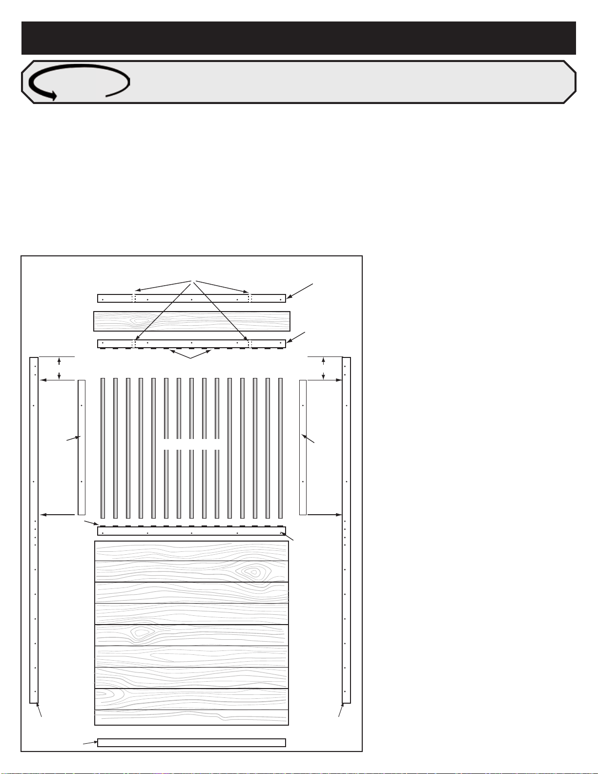
First, select the U-channel for the type of wall partition to be installed. Install
one U-channel in the center on either the corner or outside wall at + or - 1”
above the stall floor.
STEP 2
Cut all the necessary lumber to a length 1/4" to 3/8" less than the distance
measured between the inside faces of the U-channels.
STEP 3
Installing the lumber in the U-channels
3a. Slide the first board down the U-channels all the way to the floor and
ensure that it is level.
3b. Firmly secure with the screws provided.
NOTE: For solid partition walls
- Install all remaining boards and secure with the screws provided
- Install the two 94” wall braces (one each side) with the screws provided.
STEP 4 NOTE: Remaining steps are for grill partition walls.
Install all remaining boards ensuring that they come to a height of 1 1/8"
above the top of the U-channels. It may be required to rip cut a board to
achieve the correct height.
STEP 5
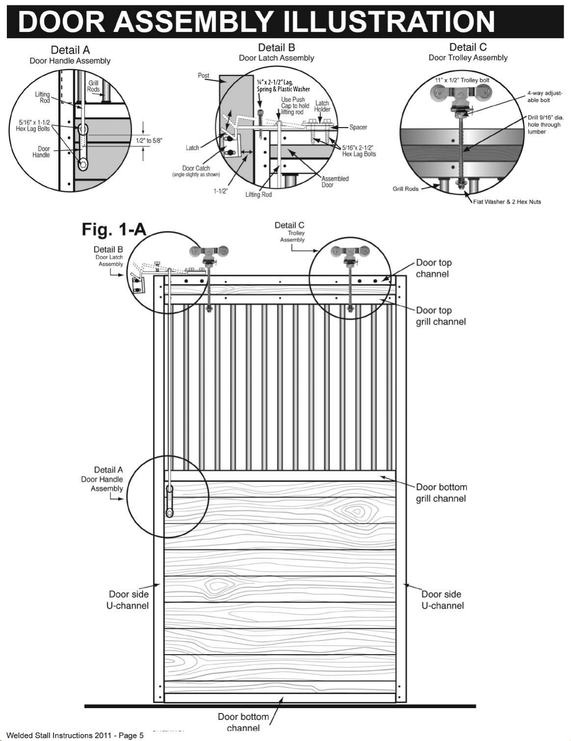
Install the rubber grommets as shown in Detail D on page 5 for both the
bottom grill channel and the corresponding top grill channel.
NOTE:
Use a soft face mallet or your fingers to install the rubber grommets into
place.
STEP 6
Install the bottom grill channel flush with the top of the U-Channels.
NOTE:
- For a 10' partition wall, two 6' and two 4' grill channel are utilized
- For a 12' partition wall, two 6' grill channels are utilized
- For a 14' partition wall, four 6' grill channels and two 21.5" channels are
utilized. NOTE: Wall sections that span over 12’ long will require a 4”
x 4” center support post.
- Install the 6' channel first by butting it flush with the face of the post. Install
the second channel for the appropriate distance. It may be necessary to
cut this component. Then attach channels with the screws provided.
STEP 7
At a height 36 3/8" install two 7" header U-channels above the top of the 46"
U-channel.
STEP 8
Place the 2” x 10” header board in the 7” U-channels allowing it to extend 1/2”
below the 7” U-channels. Use a screw at each end to hold the header board
in place for now. Put the top grill channel in position on the bottom of the
header board again hold in place with screws.
STEP 9
Insert the grill bars starting at one end. Place the grill bars in the top grill
channel then lower into the bottom grill channels, repeat until all bars are in
place. When all bars are in place, remove the screws used to hold the header
board and top grill channel. Push or pull down on the header board until it
seats evenly on the top of the grill bars. Now secure the header and top grill
channel in place with the screws provided.
STEP 10
Install the two wall braces, 46" for grilled walls or 94 1/2” for solid walls,
placing one on each side of the wall opposite each other and centred in the
partition.
FEED DOOR STYLES
Hinge
Point
Pull down
& open
Hinge
Point
Swing-Out Feed
Door Installation
1. First decide where you want the
swing-out feed door located.
2. Omit 7 bars from the grill section
(Stay at least one bar from either
end of the grill section)
3. The swing-out feed door comes
completely assembled and ready
for installation and is installed in
the same way as the grill bars.
Feed Opening
Installation
1. First decide where you want the feed
opening.
2. Cut two bars to the desired length, 22”
long bars will leave approximately a 12”
opening.
3. Slide feed opening over the two outer
bars of the opening. Let the feed opening
plate rest on the bottom grill channel.
Insert the two cut bars in the top grill
channel and slide the feed opening up
until it is tight with the two bars. Use the
self-drilling self-tapping screws to hold
the feed opening plate in place. Note:
Screw through feed opening plates into
the outer bars of the opening. Place
screw at all four corners as shown.
FLIP DOWN V-DOOR
FliDr
V-Door
Installation
The V-Door grill section is delivered pre-1.
assembled as one-piece
Follow the Stall Door Assembly steps as2.
outlined on page 7 with Step 3 omitted
V-Door not exactly as shown.