manuals.online logo
Brands
  1. Home
  2. •
  3. Brands
  4. •
  5. System Sensor
  6. •
  7. Security Sensor
  8. •
  9. System Sensor JTWB-BCD-5151EIS User manual

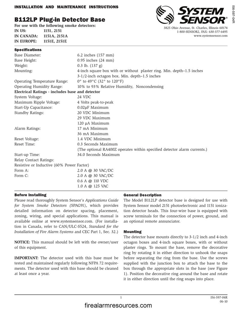
System Sensor JTWB-BCD-5151EIS User manual

1 I56-5151-007C
JTWB-BCD-5151EIS 型点型感温火灾探测器(防爆型)
安装、维护及使用说明书
安装探测器之前,请仔细阅读本说明书,以便正确地使用和维护探测器。
概述
JTWB-BCD-5151EIS 型感温(防爆型)火灾探测器是一种传统型两线本质安全型感温探测器。设计这类探测器是为了对开放式区
域提供保护,且需与兼容的控制器(接口模块)配套使用。探测器采用现代工艺技术的热敏元件快速反应电路。可适用于各种恶劣环境,
维护简便,故障率低。探测器的2个红色的LED灯正常状态每5秒闪烁一次,故障状态不闪烁;报警状态时锁定恒亮,报警的复位可由瞬
间的断电来实现。探测器设计有门灯输出及供报警测试用的内置磁干簧管测试开关。
此型探测器为本质安全型防爆产品,符合GB3836.1-2000《爆炸性气体环境用电气设备第1部分:通用要求》和GB3836.4-2000
《爆炸性气体环境用电气设备第4部分:本质安全型“i”》的有关规定。它可用于有可燃性气体存在的危险环境。
技术条件
直径 : 104mm(安装在DZ-B401底座上)
高度 : 51mm(安装在DZ-B401底座上)
重量 : 80g(不含底座)
工作温度范围 : -10℃至 50℃
工作湿度范围 : 10%至 95% 相对湿度,无凝结
工作电压 : 8.5 至 28 VDC(必须经安全栅供电)
静态电流 : ≤120uA
报警电流 : 10mA 至 93mA(必须由控制器限流)
报警复位 : 瞬间断电
灵 敏 度 : 63℃(定温)或10℃/分钟(差温)
执行标准 : GB4716-2005 / GB3836.1-2000 / GB3836.4-2000
防爆标志 : ExiaⅡCT5
认证标示 :
软件版本:A
底座选择及接线指导
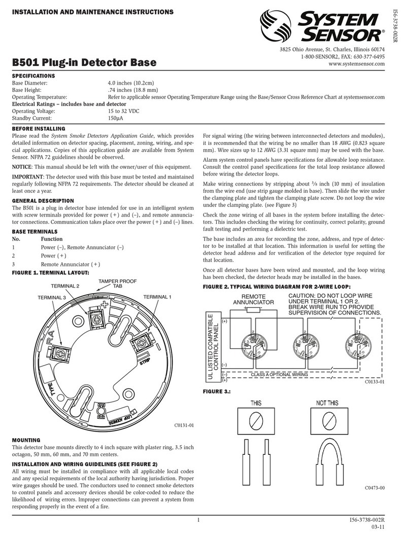
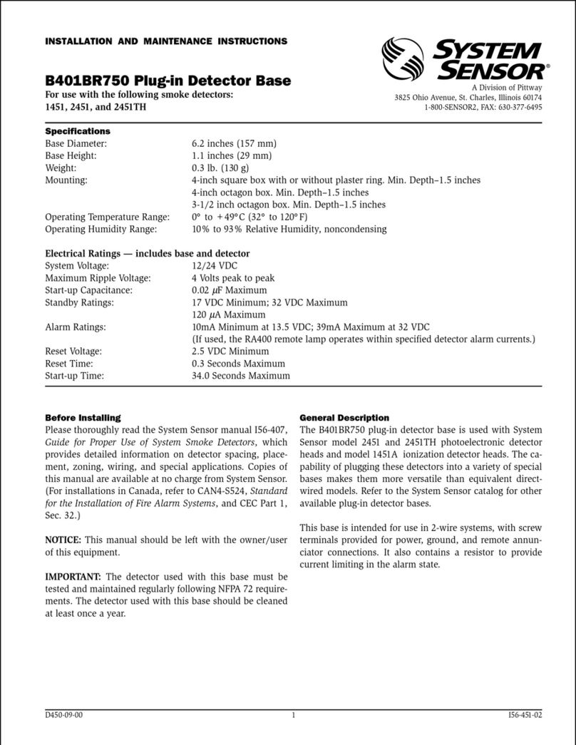
参照插接式探测器底座的说明进行接线。选用 DZ-B401 型插接式底
座或可配套使用的底座。按照所选用底座的说明书中的指导安装底座。
安装
注 意:所有接线必须符合有关标准法规。
注 意:确认全部底座已安装牢靠且每一个底座的联接线极性准确无误。
警 告:安装探测器之前,切断回路的电源。
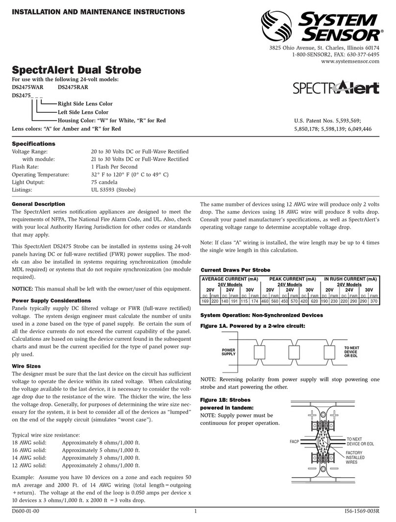
1、安装探测器:
a. 将探测器插入底座。
b. 顺时针方向旋转探测器直至其落入卡槽中。
c. 继续顺时针方向旋转探测器直至锁定就位。
防卸装置:探测器底座具有防卸功能。当启用此功能后,不用某种工具就
无法卸下探测器。有关此功能的详细使用方法见底座的安装使
用说明书。
2、待全部探测器安装完毕,向控制系统供电。
3、按照本文“测试”一节中的方法对探测器进行测试。
4、在控制器上进行复位。
5、通知有关管理部门系统开始运行。
测试
在测试之前,通告有关管理部门,感温探测器系统将进行维护,系统
会因此而临时停止工作。切断将进行维护的区域或系统的逻辑控制功能,
以免造成不必要的报警联动。
西安高新技术开发区团结南路28号
中国 陕西 西安 邮编:710075
电话: (029) 85387800 传真: (029)88332959
西安盛赛尔电子有限公司
图1
2 I56-5151-007C
在探测器安装后或定期维护后必须进行测试。本型号探测器可按以下步骤测试:
A. 测试磁铁
1. 将磁铁置于外壳上与测试标识相对边的位置处( 见图 1 )。
2. LED 应在 10 秒钟内锁定恒亮。如果 LED 未亮,检查探测器电源及底座接线。
3. 在系统控制器上复位。
B.直接加热法(1000-1500W 电吹风)
将热风直对探测器侧边(见图 1),热源距探测器保持 15cm 左右距离,以免损坏外壳。
注意:
1、如果探测器报警。只有等到其冷却下来并使其电源瞬间中断方可复位。检查所使用的控制器确定复位开关(或其它辅助设备)
是否将探测器回路的电源短暂切断。
2、如果用非本质安全方法进行测试,操作必须在危险环境以外进行。
以上测试不合格的探测器应按本文“维护保养”一节所述进行清洁处理,而后再进行测试,如果探测器还不能通过这些测试,则应
返回维修。
维护保养
本探测器从设计上是按尽可能免维护进行的,然而,一般空气中的浮尘会日积月累附着在探测器的敏感元件上并导致其灵敏度下
降。每年应对所有探测器至少进行一次的测试和清理,而在灰尘较大场合使用的探测器应更频繁测试和清理。发生火灾后必须立即清
洁并测试探测器。清洁之前,通知有关管理部门系统将进行维护,因而要临时停止工作。切断将进行维护的区域或系统的逻辑控制功
能,以免无谓的报警联动。
注意:维修时不能随意更换或改动影响防爆性能的元器件和结构。可按以下步骤进行清洁处理:
1、 从底座上卸下探测器。
2、 用吸尘器清理探测器室内的浮尘、杂物。
3、 重新安装探测器。
4、 按“测试”一节所述对探测器进行测试。
系统配置图
如图 2 所示,系统由控制器、肖特基齐纳二极管安全栅或隔离栅、防爆探测器、DZ-B401 底座与导线组成。
兼容控制器
(如果要求其对电压不能
超过250Vrms或250VDC,
则应特别指出)
肖特基齐纳
二极管安全栅
或隔离栅
[Exia]ⅡC
3 2 4
(B401底座)
防爆探测器
Exia
ⅡC T5
至下一
探测器
危险场合
注2 注3
安全场合
1) 探测器本质安全防爆参数:Ui:28VDC li:93mA Pi:0.65W Ci:0 Li:0 当本产品与安全栅配套组成本质安全防爆系统时,须满足以
下防爆参数匹配公式:Uo≤Ui,Io≤Ii,Po≤Pi,Co≥Ci+Cc,Lo≥Li+Lc 公式中 Uo、Ui、Io、Ii、Po、Pi、Co、Ci、Lo、Li 定义见 GB3836.4-2000
标准,Cc、Lc 分别为探测器与安全栅之间及探测器与远程指示器之间连接导线或电缆总的分布电容和分布电感。
2) 探测器在爆炸危险环境 0 区使用时,向安全栅供电的电源变压器须满 足 GB3836.4-2000 标准 8.1 条要求。
3)探测器的现场安装须符合 GB3836.15-2000《爆炸性气体环境用电气设备第 15 部分:危险场所电气安装(煤矿除外)》标准相关规
定。
4) 探测器外壳禁止用干布擦拭!
5) 危险场合的电子线路必须承受对地或仪器外壳 1 分钟时间的交流测试电压 500Vrms。
6)与布线:探测器及 DZ-B401 底座的安装及预埋盒尺寸可参看 DZ-B401 底座的说明书。
产品标签日期码构成说明
产品的日期码由四位数组成:第一位表示生产年份的末位数字,第二位和第三位表示生产的月份,第四位表示当月的第几周。
X X X X
表示:“生产年的末位数” “生产月份” “当月第几周”
感温探测器的局限性
本感温探测器设计为触发并启动应急装置的,没有电源不能工作。感温探测器本身也有探测局限性而且不可能寿命无限。
质量保证
西安盛赛尔公司对所生产的探测器产品实行三年保修。如果是由于人为损坏、使用不当或自行调整改动产品而导致失效的产品,不属
于本保修范围,而因此造成的后果西安盛赛尔公司将不负责任。
LED
ᣛ⼎♃
ᑆㇻㅵ
⌟䆩󰵼䆚
ᑆㇻㅵ
⌟䆩
ᑆㇻㅵ
⌟䆩󰵼䆚
ᑆㇻㅵ
⌟䆩
⛁亢
3 I56-5151-007C
Specifications
Diameter : 104 mm (Installed in DZ-B401 Base)
Height : 51mm( Installed in DZ-B401 Base)
Weight : 80g(Without Base)
Operating Temperature Range : -10°C to 50°C
Operating Humidity Range : 10% to 95% Relative Humidity noncondensing
Operating voltage : 8.5 to 28VDC
Standby Current : ≤120uA
Alarm Current : 10mA Min. 93mA Max. (Must be limited by control panel)
Latching Alarm : Reset by momentary power interruption
Sensitivity : 63°C Fixed or 10°C /min rate-of-rise
Standard : GB4716-2005 / GB3836.1-2000 / GB3836.4-2000
Intrinsic Safety Rating : Exia ⅡC T5
Certification : Software Version:A
BEFORE INSTALLING
Before In stalling please thor oughly r ead the X i’an Syst em Sensor manu al, Copies o f this manu al ar e available from Xi’an System
Sensor.
GENERAL DESCRIPTION
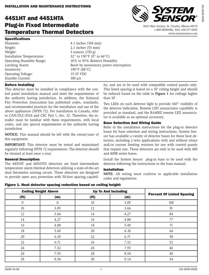
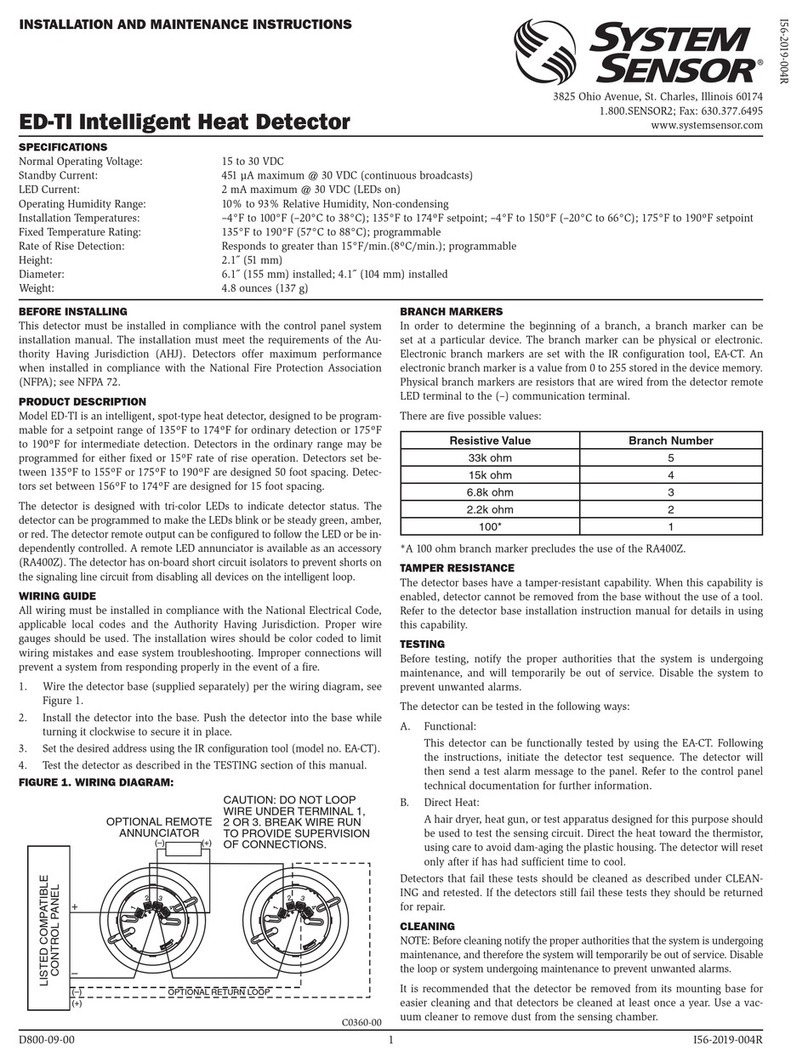
JTWB-BCD-5151EIS/HT is a conventional 2-wire intrinsically safe thermal detector. This detector is designed to provide open area
protection and to be used with compatible panels (or interface module) only. This sensor utilizes a state-of-the-art thermistor sensing
circuit for fast response. It can be used in every environmental condition and also has the simple maintenance and lower fault rate
advantages. Two red LEDs blink in standby each 5S and latch on in alarm, and do not blink in trouble. A remote output option is also
available. A built in test switch is used in the detector for test alarm. The detector is commpliance with the GB3836.1-2000
&GB3836.4-2000 standards requiremets.
INSTALLATION
NOTE: All wiring must comply with all applicable national codes of practice and regulations.
WARNING: Disconnect the power to the initiating device before installing the detectors.
1. Install detectors:
a. Place the detector into the detector base.
b. Turn the detector clockwise until the detector drops into
place.
c. Continue turning detector clockwise to lock it in place.
Tamper Resistance: T he d etector b ases can be made tamper
resistant. Whe n capabilit y is enabled, de tectors cannot be removed
from the base without t he u se o f a tool. See the detector base
installation ma nual of the de tector base for details in us ing this
capability
2. After all detectors have been installed, apply power to the control
unit.
3. Test the detector using the magnet as described under TESTING.
4. Reset the detector at the system control panel.
5. Notify the proper authorities that the system is back on line
.
TESTING
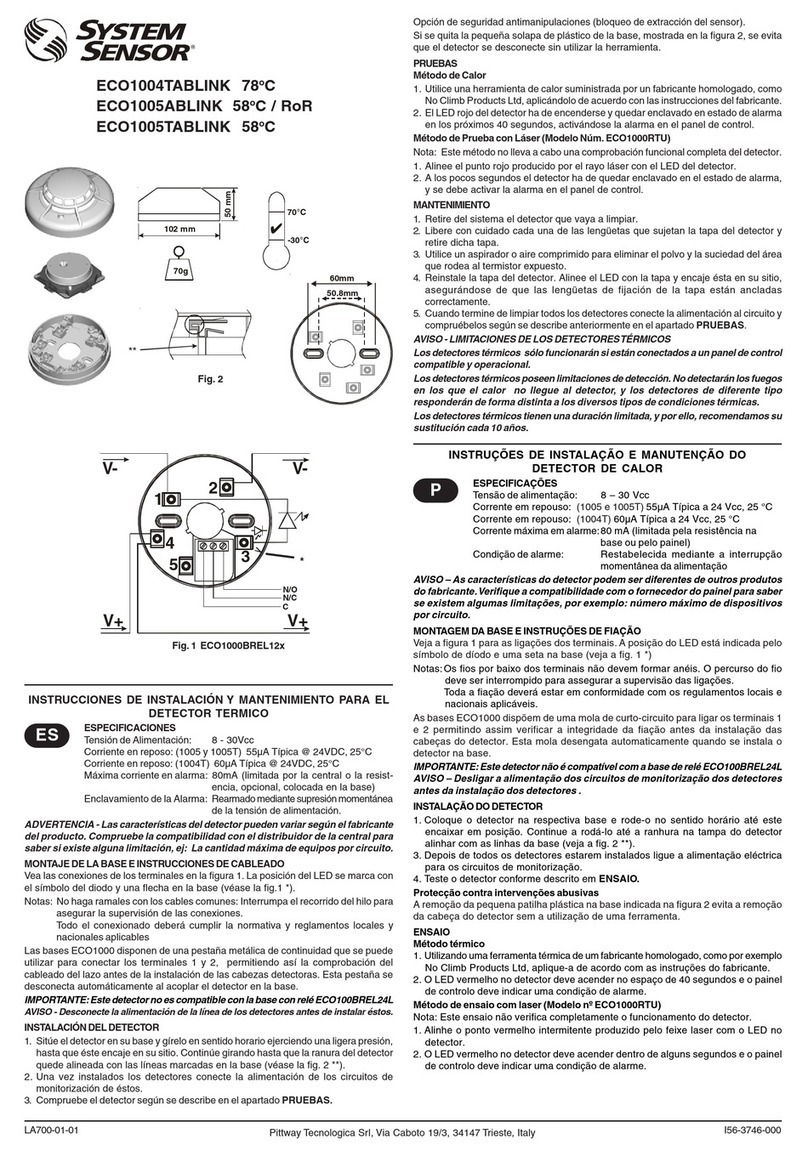
A. Test Magnet
1. Place the magnet against the cover in the location designated by
the raised mark to activate the test feature (see Figure 1).
2. The LEDs should latch ON within 5 seconds indicating alarm and
an-nunciating the panel.
INSTALLATION AND MAINTENANCE INSTRUCTIONS
Model JTWB-BCD-5151EIS
Plug-in
Intrinsically Safe Thermal Detector
with Fixed Temperature Alarm
28 Tuan Jie South Road, Xi’an Nationa
l
Hi-tech Industrial Develo
p
ment Zone
Province of Shaanxi, 710075, China
Telephone: (029) 85387800 Fax: (029) 88332959
Figure 1.
4 I56-5151-007C
3. Reset the detector at the system control panel.
B. Direct Heat Method (Hair dryer of 1000 - 1500 watts)
From the side of the d etector, direct the heat t oward the sensor. Hold the h eat source ab out 15 cm away to prevent da mage to th e
cover during testing
NOTE: If a detector goes into alarm, it will reset only if the detector has cooled and if its power is momentarily interrupted. Check the
control panel being used to determine whether the RESET switch (or some other auxiliary device or control) momentarily cuts off power
to the detector loop.
Detectors that fail these tests should be cleaned as desc ribed under M AINTENANCE and retested. If the detectors still fail thes e test s
they should be returned for repair.
MAINTENANCE
The JTWB-BCD-1151EIS/HT det ector has been designed to b e as m aintenance free as possible . Normal ai r-borne d ust, however, can
accumulate on the detector’s sensing elements and cause them to become less sensitive. All detectors should be tested and cleaned at least
once a year, and those in dustier areas should be tested and cleaned more often. Detectors must also be cleaned and tested immediately
after a f ire. Before c leaning, notif y the proper authorities that the system is und ergoing maintenance, and therefore the system w ill
temporarily be out of service. Disable the loop or system undergoing maintenance to prevent unwanted alarms.
1. Remove detector from mounting base.
2. Use a vacuum cleaner to remove dust from the sensing chamber.
3. Reinstall the detector.
4. Test detector as described under TESTING.
SYSTEM WIRING DIAGRAM
The system includes the control panel, the zener diode safety barrier or the isolated barrier, the intrinsically detector, the DZ-B401 base
and the wires.
Intrinsic
Safety Barrier
[Exia]ⅡC
3 2 4
(B401 Base)
Detector
Exia
ⅡC T5
To next
detector
HAZARDOUS AREA
Note 2 Note 3
SAFE AREA
Safe area apparatus
,
which is
unspecified except that it must
not be suppliedo from or contain
under normal or abnormal condi-
ions a source of potential with
respect to earth in excess of
250Vrms or 250VDC
Notes:
1. The detector has the following Intrinsically-safe parameters: Ui: 28VDC, Li: 93mA, Pi: 0.65W, Ci: 0, Li: 0 When to compatible with
the S afety b arrier, th e parameters mu st b e c omplied w ith t he fo llowing formula: Uo ≤Ui, I o≤Ii, Po ≤Pi, Co ≥Ci+Cc, L o≥Li+Lc,
Among them, about the definitions of Uo、Ui、Io、Ii、Po、Pi、Co、Ci、Lo、Li refer to the GB3836.4-2000. Cc and Lc separately stand
for the capacitance and inductance between the detector and the safety barrier, the remote indicator or the general cable.
2. The transformer in the hazardous area must be accordance with the Item 8.1 of the GB3836.4-2000 standard.
3. The installation must comply with the Item 15 of the GB3836.15-2000 standard.
4. Don’t clean the detector housing with a dry cloth.
5. The electrical circuit in the hazardous area must be capable of withstanding an A.C. test voltage of 500VRMS to earth or frame of the
apparatus for one minute.
6. Zone wiring of the detector bases refer to the DZ-B401 base installation manual.
PRODUCT NAMEPLATE DATE CODE NOTE
X X X X
Stands for: The end number of the producing year t he producing month the week of the month
LIMITATIONS OF FIRE ALARM SYSTEMS
This smoke sensor is designed to activate and initiate emergency action. It will not work without power and it has its limitations. It also
can not last forever.
THREE-YEAR LIMITED WARRANTY
Xi’an System Sensor warrants its enclosed thermal detector to be free from defects in materials and workmanship under normal use and
service for a period of three years from date of manufacture. The Company’s obligation of this Warranty shall be limited to the repair or
replacement o f any p art o f the thermal dete ctor which is found to be d efective in materials or workmanship und er n ormal u se and
service during the three year period commencing with the date of manufacture.
Ver. A
LED Status
Indicators
Magnet Test
Marker
Test Magnet
Position
Test Magnet
Position
Magnet Test
Marker
HEAT
Other System Sensor Security Sensor manuals

System Sensor B110RLP User manual

System Sensor

System Sensor B110RLP User manual

System Sensor Smoke Detector Spacing on Level Ceilings with Beams and... Quick reference guide

System Sensor

System Sensor Smoke Detector Spacing on Level Ceilings with Beams and... Quick reference guide

System Sensor B200SR User manual

System Sensor

System Sensor B200SR User manual

System Sensor B501-WHITE User manual

System Sensor

System Sensor B501-WHITE User manual

System Sensor B112LP User manual

System Sensor

System Sensor B112LP User manual

System Sensor 2112LP User manual

System Sensor

System Sensor 2112LP User manual

System Sensor 9440X FAAST User manual

System Sensor

System Sensor 9440X FAAST User manual

System Sensor FAAST LT FL01 Series User manual

System Sensor

System Sensor FAAST LT FL01 Series User manual

System Sensor WFDEXP User manual

System Sensor

System Sensor WFDEXP User manual

System Sensor B524IEFT-1 User manual

System Sensor

System Sensor B524IEFT-1 User manual

System Sensor WFDT User manual

System Sensor

System Sensor WFDT User manual

System Sensor DH400 User manual

System Sensor

System Sensor DH400 User manual

System Sensor B501A User manual

System Sensor

System Sensor B501A User manual

System Sensor B110LP User manual

System Sensor

System Sensor B110LP User manual

System Sensor B501AUS User manual

System Sensor

System Sensor B501AUS User manual

System Sensor ECO1004TABLINK User manual

System Sensor

System Sensor ECO1004TABLINK User manual

System Sensor 2300TB User manual

System Sensor

System Sensor 2300TB User manual

System Sensor B210LPA User manual

System Sensor

System Sensor B210LPA User manual

System Sensor FAAST 9400X User manual

System Sensor

System Sensor FAAST 9400X User manual

System Sensor B110LPA User manual

System Sensor

System Sensor B110LPA User manual

System Sensor B110LP User manual

System Sensor

System Sensor B110LP User manual

System Sensor B224RB User manual

System Sensor

System Sensor B224RB User manual

System Sensor 1112/24D User manual

System Sensor

System Sensor 1112/24D User manual

System Sensor SpectrAlert MP120K User manual

System Sensor

System Sensor SpectrAlert MP120K User manual

Popular Security Sensor manuals by other brands

3M 600 Series datasheet

3M

3M 600 Series datasheet

EDTM RD1850 Operator's manual

EDTM

EDTM RD1850 Operator's manual

PNI SAFE HOUSE DUAL GAS 250 user manual

PNI

PNI SAFE HOUSE DUAL GAS 250 user manual

Texecom Premier Elite MR Long Range installation manual

Texecom

Texecom Premier Elite MR Long Range installation manual

Triple Plus CLM-FDAMAP-1-00 quick start guide

Triple Plus

Triple Plus CLM-FDAMAP-1-00 quick start guide

Bosch Blue Line Q1 installation instructions

Bosch

Bosch Blue Line Q1 installation instructions

Bircher Reglomat PrimeMotion B Original instructions

Bircher Reglomat

Bircher Reglomat PrimeMotion B Original instructions

teko Astra-3321 user guide

teko

teko Astra-3321 user guide

Somogyi home HS 71 Instructions for use

Somogyi

Somogyi home HS 71 Instructions for use

Gemini 807 manual

Gemini

Gemini 807 manual

Pfeiffer ASM 340 operating instructions

Pfeiffer

Pfeiffer ASM 340 operating instructions

Rohm BH1730FVC-TR Technical notes

Rohm

Rohm BH1730FVC-TR Technical notes

Aritech 700 series Installation sheet

Aritech

Aritech 700 series Installation sheet

Kanlux AKER JQ-30 manual

Kanlux

Kanlux AKER JQ-30 manual

Onan Mobile GenSet Service manual

Onan

Onan Mobile GenSet Service manual

STEINEL 067304 manual

STEINEL

STEINEL 067304 manual

B+B Sensors PIR-STD Operation manual

B+B Sensors

B+B Sensors PIR-STD Operation manual

Orbis ISIMAT INSTRUCTIONS ON USE

Orbis

Orbis ISIMAT INSTRUCTIONS ON USE

manuals.online logo
manuals.online logoBrands
  • About & Mission
  • Contact us
  • Privacy Policy
  • Terms and Conditions

Copyright 2025 Manuals.Online. All Rights Reserved.