manuals.online logo
Brands
  1. Home
  2. •
  3. Brands
  4. •
  5. System Sensor
  6. •
  7. Security Sensor
  8. •
  9. System Sensor L-Series User manual

System Sensor L-Series User manual

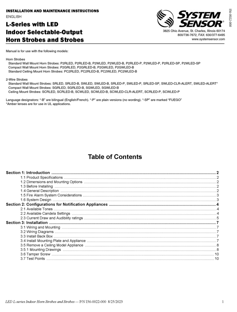
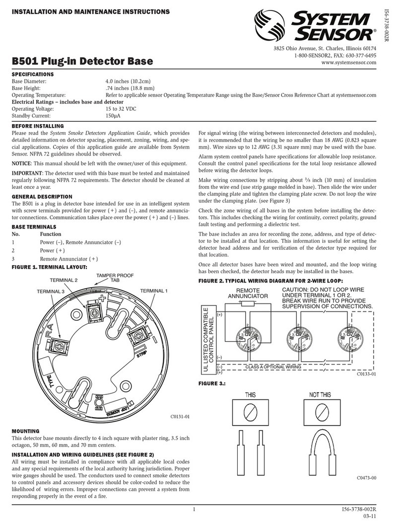
GENERAL DESCRIPTION
L-Series color lenses come in four colors options including amber, blue, green
and red. The lenses are compatible with L-Series strobes including wall or
ceiling mount. Note that color lenses must only be used with devices that are
not re printed.
Color lens strobes are UL Listed under 1638 (Visual Signaling Appliances)
for Private Mode General Utility Signaling. UL 1638 measures light output of
strobe devices on-axis (straight on). See table below for candela color de-
ratings. Each candela rating shall be reduced by the listed percentages below.
TABLE 1. CANDELA DE-RATING BY LENS COLOR
Lens
Color
Effective Light Loss
for LED Units
Amber 0%
Blue 0%
Green -55%
Red -65%
WARNING
Not to be used as a Visual Public Mode Alarm Notication Appliance.
3825 Ohio Avenue, St. Charles, Illinois 60174
800/736-7672, FAX: 630/377-6495
www.systemsensor.com
INSTALLATION AND MAINTENANCE INSTRUCTIONS
L-Series with LED
Color Lenses
For use with the following models:
LENS-A3, LENS-B3, LENS-G3, LENS-R3
I56-5102-003
INSTALLATION
For L-Series models, please follow the instructions below for installing colored
lenses.
1. Before applying the color lens to the strobe, clean the area around the
strobe lens.
2. Remove the red liner from the back of the color lens gently. Make sure that
the clear adhesive is still attached to the bottom at surface of the lens.
3. Center the lens with respect to the countersink around the lens on the
device.
4. Apply and press the lens against the unit.
NOTE: Installing the lens adds about 0.125” (3.12mm) to appliance height.
System Sensor®is a registered trademark of Honeywell International, Inc.
FIGURE 1. COLOR LENS INSTALLATION TO LED WALL MOUNT DEVICE
A0629-00
FIGURE 2. COLOR LENS INSTALLATION TO LED CEILING MOUNT
DEVICE
A0630-00
1 I56-5102-003
©2023 System Sensor. 9/5/2023
GENERAL DESCRIPTION
L-Series color lenses come in four colors options including amber, blue, green
and red. The lenses are compatible with L-Series strobes including wall or
ceiling mount. Note that color lenses must only be used with devices that are
not re printed.
Color lens strobes are UL Listed under 1638 (Visual Signaling Appliances)
for Private Mode General Utility Signaling. UL 1638 measures light output of
strobe devices on-axis (straight on). See table below for candela color de-
ratings. Each candela rating shall be reduced by the listed percentages below
for Xenon wall units only.
NOTE: No de-rating required for ceiling units.
TABLE 1. CANDELA DE-RATING BY LENS COLOR
Lens
Color
Effective Light Loss
for Xenon Wall Units
Amber 0%
Blue -40%
Green -65%
Red -85%
WARNING
Not to be used as a Visual Public Mode Alarm Notication Appliance.
3825 Ohio Avenue, St. Charles, Illinois 60174
800/736-7672, FAX: 630/377-6495
www.systemsensor.com
INSTALLATION AND MAINTENANCE INSTRUCTIONS
L-Series Color Lenses (Xenon)
For use with the following models:
LENS-A2, LENS-B2, LENS-G2, LENS-R2, LENS-AC2, LENS-BC2, LENS-GC2, LENS-RC2
I56-5102-003
INSTALLATION
For L-Series models, please follow the instructions below for installing colored
lenses.
1. Before applying the color lens to the strobe, clean the area around the
strobe lens.
2. Remove the red liner from the back of the color lens gently. Make sure that
the clear adhesive is still attached to the bottom at surface of the lens.
3. Align the slot on the color lens with the candela indicator window on the unit.
This is a mistake-proof step only on the wall units.
4. Apply and press the lens against the unit.
System Sensor®is a registered trademark of Honeywell International, Inc.
FIGURE 1. COLOR LENS INSTALLATION TO LEGACY WALL MOUNT
DEVICE (XENON)
A0512-00
FIGURE 2. COLOR LENS INSTALLATION TO LEGACY CEILING MOUNT
DEVICE (XENON)
A0512-00
2 I56-5102-003
©2023 System Sensor. 9/5/2023

Other manuals for L-Series

1

This manual suits for next models

4

Other System Sensor Security Sensor manuals
System Sensor FAAST LT FL01 Series User manual

System Sensor

System Sensor FAAST LT FL01 Series User manual

System Sensor WFD Series User manual

System Sensor

System Sensor WFD Series User manual

System Sensor B110RLP User manual

System Sensor

System Sensor B110RLP User manual
System Sensor 4451HTA User manual

System Sensor

System Sensor 4451HTA User manual

System Sensor ECO1002 User manual

System Sensor

System Sensor ECO1002 User manual

System Sensor B114LPBT User manual

System Sensor

System Sensor B114LPBT User manual

System Sensor B401BR User manual

System Sensor

System Sensor B401BR User manual
System Sensor WFD Series User manual

System Sensor

System Sensor WFD Series User manual

System Sensor 885WP-B User manual

System Sensor

System Sensor 885WP-B User manual
System Sensor B200SR User manual

System Sensor

System Sensor B200SR User manual

System Sensor 4451HT Technical specifications

System Sensor

System Sensor 4451HT Technical specifications

System Sensor B110LP User manual

System Sensor

System Sensor B110LP User manual

System Sensor WFD20A User manual

System Sensor

System Sensor WFD20A User manual

System Sensor SpectrAlert DS2475WAR User manual

System Sensor

System Sensor SpectrAlert DS2475WAR User manual

System Sensor B401BR750 User manual

System Sensor

System Sensor B401BR750 User manual

System Sensor ISO524-1 User manual

System Sensor

System Sensor ISO524-1 User manual

System Sensor WFDT User manual

System Sensor

System Sensor WFDT User manual

System Sensor ED-TI User manual

System Sensor

System Sensor ED-TI User manual

System Sensor B404B User manual

System Sensor

System Sensor B404B User manual

System Sensor SpectrAlert Advance CHSR User manual

System Sensor

System Sensor SpectrAlert Advance CHSR User manual

System Sensor B401BR User manual

System Sensor

System Sensor B401BR User manual

System Sensor 2151 User manual

System Sensor

System Sensor 2151 User manual
System Sensor B501AUS User manual

System Sensor

System Sensor B501AUS User manual

System Sensor WFDNA Series Technical specifications

System Sensor

System Sensor WFDNA Series Technical specifications

Popular Security Sensor manuals by other brands

Optex SL-100 TNR installation instructions

Optex

Optex SL-100 TNR installation instructions

LEGRAND 088230 manual

LEGRAND

LEGRAND 088230 manual

SharpEye 40 user guide

SharpEye

SharpEye 40 user guide

Chorus GW 10 756 Technical manual

Chorus

Chorus GW 10 756 Technical manual

PCB Piezotronics 4115A-05A Installation and operating manual

PCB

PCB Piezotronics 4115A-05A Installation and operating manual

Honeywell IS-215T installation instructions

Honeywell

Honeywell IS-215T installation instructions

Autonics BJR Series product manual

Autonics

Autonics BJR Series product manual

SICK Prime KTS-WB9A34115A Series manual

SICK

SICK Prime KTS-WB9A34115A Series manual

olympia electronics BSR-6060/A instruction manual

olympia electronics

olympia electronics BSR-6060/A instruction manual

BR 700-PRO user manual

BR

BR 700-PRO user manual

Evikon PluraSens E2648-ETO user manual

Evikon

Evikon PluraSens E2648-ETO user manual

Cabletech URZ0408 owner's manual

Cabletech

Cabletech URZ0408 owner's manual

INIM qtech QDT500H Installation and programming manual

INIM

INIM qtech QDT500H Installation and programming manual

Protect Security Sounder installation manual

Protect

Protect Security Sounder installation manual

Hi-Link HLK-LD2410C manual

Hi-Link

Hi-Link HLK-LD2410C manual

US Netting Defender Gate 20 instruction manual

US Netting

US Netting Defender Gate 20 instruction manual

EDTM DiamondGuard/ShowerGuard DS1670 Operator's manual

EDTM

EDTM DiamondGuard/ShowerGuard DS1670 Operator's manual

KJB Security DD3150 manual

KJB Security

KJB Security DD3150 manual

manuals.online logo
manuals.online logoBrands
  • About & Mission
  • Contact us
  • Privacy Policy
  • Terms and Conditions

Copyright 2025 Manuals.Online. All Rights Reserved.