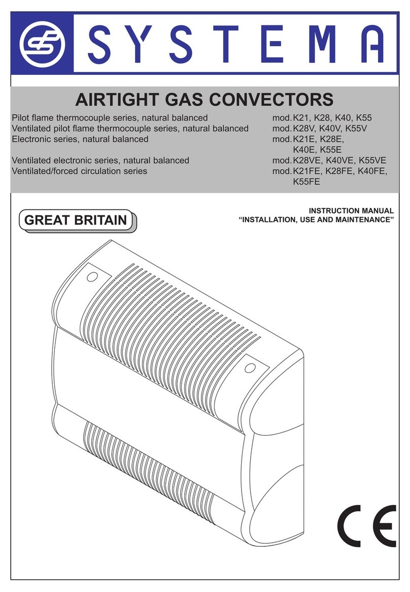
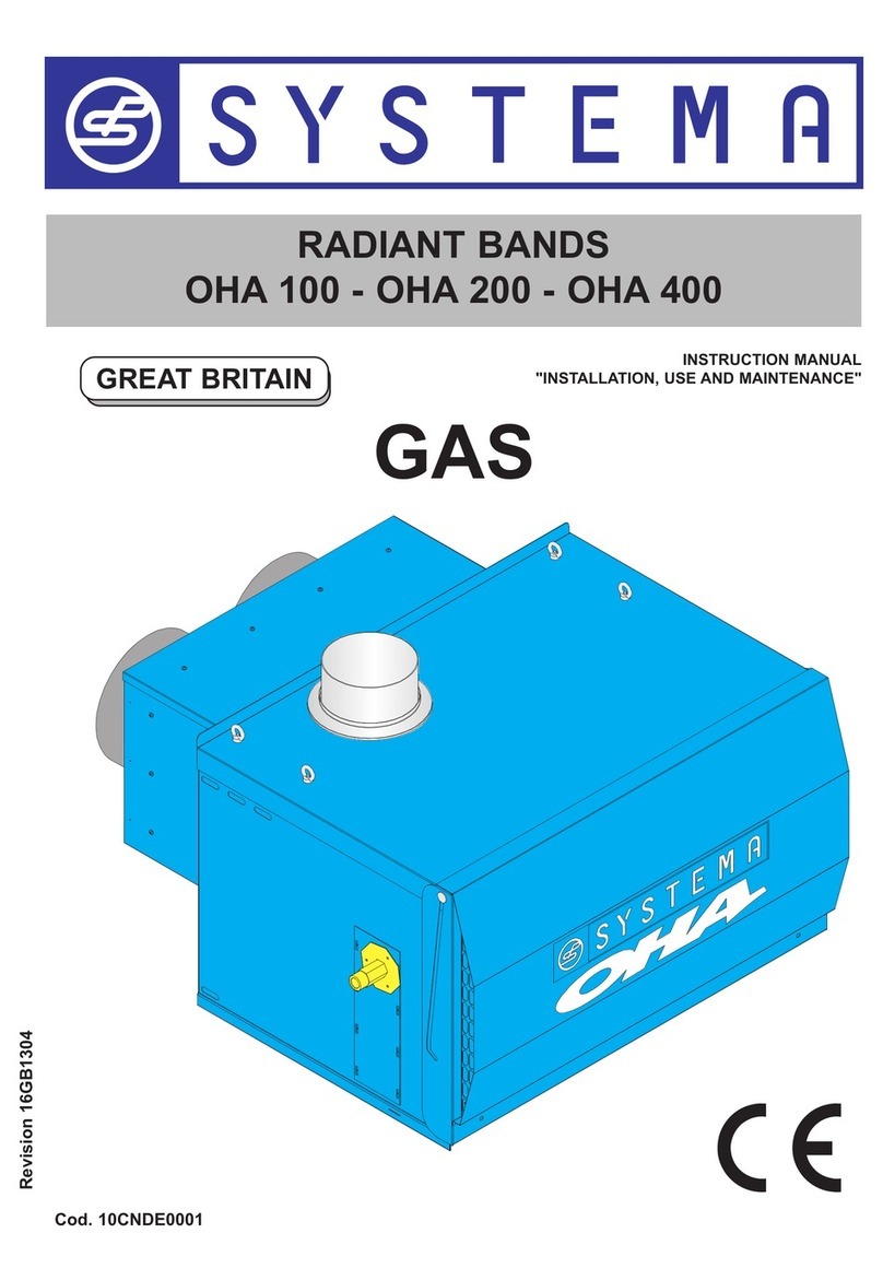
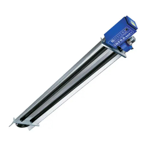
Systema EOLO BluLine BL 15 User manual

SUSPENDED WARM AIR HEATERS
EOLO BLULINE
modulating pre-mixed
versions AE and AC
Rev. 04GB1410
GB

2
Rev. 04GB1410
SYSTEMA S.p.A. EOLO BLULINE
ISO 9001:2008
SYSTEMA S.p.A.
Via Antonio Ceccon, 3
Loreggia C.A.P. 35010
PADOVA - ITALIA
Tel. +39.049.9355663 r.a.
Fax +39.049.9355699
E-mail: [email protected]
www.systema.it
IMPORTANT!!
Read carefully this manual before starting up the system.
In order to improve the product, Systema reserves the right to modify the contents without any
notice.

3Rev. 04GB1410
SYSTEMA S.p.A.
EOLO BLULINE
SUMMARY
1 GENERAL RULES . . . . . . . . . . . . . . . . . . . . . . . . . . . . . . . . . . . . . . . . . . . . . . . . . . . . .5
1.1 GENERAL WARNINGS . . . . . . . . . . . . . . . . . . . . . . . . . . . . . . . . . . . . . . . . . . . . . . . . . . . . . . . . . . . . .5
1.2 CONSTRUCTION FEATURES . . . . . . . . . . . . . . . . . . . . . . . . . . . . . . . . . . . . . . . . . . . . . . . . . . . . . . . .7
1.3 TECHNICAL DATA . . . . . . . . . . . . . . . . . . . . . . . . . . . . . . . . . . . . . . . . . . . . . . . . . . . . . . . . . . . . . . . . .8
1.4 MAIN COMPONENTS . . . . . . . . . . . . . . . . . . . . . . . . . . . . . . . . . . . . . . . . . . . . . . . . . . . . . . . . . . . . . .9
1.4.1 Burner . . . . . . . . . . . . . . . . . . . . . . . . . . . . . . . . . . . . . . . . . . . . . . . . . . . . . . . . . . . . . . . . . . . . . . . . . . . . . . . . .9
1.4.2 Controls . . . . . . . . . . . . . . . . . . . . . . . . . . . . . . . . . . . . . . . . . . . . . . . . . . . . . . . . . . . . . . . . . . . . . . . . . . . . . . . .9
1.4.3 Fans . . . . . . . . . . . . . . . . . . . . . . . . . . . . . . . . . . . . . . . . . . . . . . . . . . . . . . . . . . . . . . . . . . . . . . . . . . . . . . . . . .9
1.4.4 Performance diagrams AC Fans - MV fans referring table 1.4.3 . . . . . . . . . . . . . . . . . . . . . . . . . . . . . . . . . . .10
1.4.5 Performance curves of EOLO AC - Fans NICOTRA . . . . . . . . . . . . . . . . . . . . . . . . . . . . . . . . . . . . . . . . . . . .12
1.4.5.a Fans performance curves 9/7 NICOTRA for Eolo 15-25 (230V - 50Hz) . . . . . . . . . . . . . . . . . . . . . . . . . . . . . .12
1.4.5.b Fans performance curves 10/10 NICOTRA for Eolo 35 and 65 (230V - 50Hz) . . . . . . . . . . . . . . . . . . . . . . . . .13
1.4.5.c Fans performance curves 10/10 NICOTRA for Eolo 35 and 65 (230V - 60Hz) . . . . . . . . . . . . . . . . . . . . . . . . .14
1.4.5.d Fans performance curves for 12/9 NICOTRA for Eolo 45 and 85 (230V - 50Hz) . . . . . . . . . . . . . . . . . . . . . . .15
1.4.5.e Fans performance curves 12/12 NICOTRA for Eolo 55 and 100 (230V - 60Hz) . . . . . . . . . . . . . . . . . . . . . . . .16
1.4.5.f Fans performance curves 12/12 NICOTRA for Eolo 55 and 100 (230V - 50Hz) . . . . . . . . . . . . . . . . . . . . . . . .17
1.5 DIMENSIONS Eolo BLULINE AE - helicoidal fans version . . . . . . . . . . . . . . . . . . . . . . . . . . . . . . .18
1.6 DIMENSIONS Eolo BLULINE AC - Centrifugal fans version . . . . . . . . . . . . . . . . . . . . . . . . . . . . . .19
1.7 EXPLODED VIEW . . . . . . . . . . . . . . . . . . . . . . . . . . . . . . . . . . . . . . . . . . . . . . . . . . . . . . . . . . . . . . . .20
1.7.1 Eolo BLULINE AE helicoidal version . . . . . . . . . . . . . . . . . . . . . . . . . . . . . . . . . . . . . . . . . . . . . . . . . . . . . . . . .20
1.7.2 Eolo BLULINE AC centrifugal series . . . . . . . . . . . . . . . . . . . . . . . . . . . . . . . . . . . . . . . . . . . . . . . . . . . . . . . . .20
1.8 BURNER EXPLODED VIEW . . . . . . . . . . . . . . . . . . . . . . . . . . . . . . . . . . . . . . . . . . . . . . . . . . . . . . . .22
2 ELECTRICAL PLANT . . . . . . . . . . . . . . . . . . . . . . . . . . . . . . . . . . . . . . . . . . . . . . . . . .23
2.1 MAIN ELECTRONIC BOARD SCP674V010 GENERAL CHARACTERISTICS . . . . . . . . . . . . . . . . .23
2.1.1 OPERATION . . . . . . . . . . . . . . . . . . . . . . . . . . . . . . . . . . . . . . . . . . . . . . . . . . . . . . . . . . . . . . . . . . . . . . . . . . .23
2.1.2 ALARM OPERATION AND RESET . . . . . . . . . . . . . . . . . . . . . . . . . . . . . . . . . . . . . . . . . . . . . . . . . . . . . . . . .23
2.1.3 AUXILIARY CONTROL FAN . . . . . . . . . . . . . . . . . . . . . . . . . . . . . . . . . . . . . . . . . . . . . . . . . . . . . . . . . . . . . . .24
2.1.5 DISPLAY/MODIFICATION OF INSTRUMENTS PARAMETERS . . . . . . . . . . . . . . . . . . . . . . . . . . . . . . . . . . .24
2.1.6 DISPLAY INDICATIONS SCP674V010 . . . . . . . . . . . . . . . . . . . . . . . . . . . . . . . . . . . . . . . . . . . . . . . . . . . . . . .25
2.2 ELECTRICAL DIAGRAM 230 VAC MONOPHASE EOLO BLULINE AE-AC . . . . . . . . . . . . . . . . . . .25
2.3 SCHEMA ELETTRICO ALIMENTAZIONE TRIFASE 400 V 50 Hz . . . . . . . . . . . . . . . . . . . . . . . . . . .26
2.4 ON/OFF CONTROL BOARD CONNECTION DIAGRAM . . . . . . . . . . . . . . . . . . . . . . . . . . . . . . . . . .27
2.5 CONNECTION DIAGRAM OF COMBUSTION UNIT AND THE INET NETWORK CONTROL BOARD
FOR A SINGLE UNIT . . . . . . . . . . . . . . . . . . . . . . . . . . . . . . . . . . . . . . . . . . . . . . . . . . . . . . . . . . . . . .28
2.5.1 Configuration of the electric board SCP674V010, modulating operation of INET panel . . . . . . . . . . . . . . . . .28
2.6 CONNECTION DIAGRAM OF THE ELECTRIC CONTROL BOARD OF INET NETWORK WITH THE
ZONE PROBES FOR ONE OR MORE COMBUSTION GROUPS . . . . . . . . . . . . . . . . . . . . . . . . . . .29
2.7 CONNECTION DIAGRAM COMBUSTION UNIT AND INET NETWORK CONTROL BOARD FROM 2 TO
16 UNITS . . . . . . . . . . . . . . . . . . . . . . . . . . . . . . . . . . . . . . . . . . . . . . . . . . . . . . . . . . . . . . . . . . . . . . .30
2.7.1 Configuration of the board inside the machine SCP674V010 for functioning with several combustion units and the
INET control board . . . . . . . . . . . . . . . . . . . . . . . . . . . . . . . . . . . . . . . . . . . . . . . . . . . . . . . . . . . . . . . . . . . . . .31
2.8 CONNECTION DIAGRAM COMBUSTION UNITS AND CE ON/OF CONTROL BOARD code
04CEQU1204 . . . . . . . . . . . . . . . . . . . . . . . . . . . . . . . . . . . . . . . . . . . . . . . . . . . . . . . . . . . . . . . . . . . .32
2.9 CONNECTION DIAGRAM COMBUSTION UNITS AND CE ON/OFF CONTROL BOARD code
04CEQU1202 and 04CEQU1203 . . . . . . . . . . . . . . . . . . . . . . . . . . . . . . . . . . . . . . . . . . . . . . . . . . . . .33

4
Rev. 04GB1410
SYSTEMA S.p.A. EOLO BLULINE
3 GAS PIPES . . . . . . . . . . . . . . . . . . . . . . . . . . . . . . . . . . . . . . . . . . . . . . . . . . . . . . . . . .34
3.1 EQUIPMENT CONNECTION . . . . . . . . . . . . . . . . . . . . . . . . . . . . . . . . . . . . . . . . . . . . . . . . . . . . . . . .34
4 INSTALLATION . . . . . . . . . . . . . . . . . . . . . . . . . . . . . . . . . . . . . . . . . . . . . . . . . . . . . . .35
4.1 WALL INSTALLATION EXAMPLES . . . . . . . . . . . . . . . . . . . . . . . . . . . . . . . . . . . . . . . . . . . . . . . . . .36
4.2 EXAMPLES OF INSTALLATIONS OF EOLO AT A WALL WITH RORATING BRACKET (OPTIONAL)37
4.3 CENTRIFUGAL INSTALLATION EXAMPLE . . . . . . . . . . . . . . . . . . . . . . . . . . . . . . . . . . . . . . . . . . . .38
5 EXHAUST AND SUCTION DUCTS . . . . . . . . . . . . . . . . . . . . . . . . . . . . . . . . . . . . . . .39
5.1 SEPARATE WALL DISCHARGE TYPE C13 . . . . . . . . . . . . . . . . . . . . . . . . . . . . . . . . . . . . . . . . . . . .40
5.2 WALL DISCHARGE TYPE B23 . . . . . . . . . . . . . . . . . . . . . . . . . . . . . . . . . . . . . . . . . . . . . . . . . . . . . .40
5.3 SEPARATE ROOF DISCHARGE TYPE C33 . . . . . . . . . . . . . . . . . . . . . . . . . . . . . . . . . . . . . . . . . . . .41
5.4 ROOF DISCHARGE TYPE B23 . . . . . . . . . . . . . . . . . . . . . . . . . . . . . . . . . . . . . . . . . . . . . . . . . . . . . .41
5.5 COAXIAL ROOF DISCHARGE TYPE C33 . . . . . . . . . . . . . . . . . . . . . . . . . . . . . . . . . . . . . . . . . . . . .42
5.6 COAXIAL WALL DISCHARGE TYPE C33 . . . . . . . . . . . . . . . . . . . . . . . . . . . . . . . . . . . . . . . . . . . . .42
6 TESTING AND EQUIPMENT START UP . . . . . . . . . . . . . . . . . . . . . . . . . . . . . . . . . . .43
6.1 PRELIMINARY OPERATIONS . . . . . . . . . . . . . . . . . . . . . . . . . . . . . . . . . . . . . . . . . . . . . . . . . . . . . . .43
6.2 STARTING AND RUNNING OF THE GENERATORS . . . . . . . . . . . . . . . . . . . . . . . . . . . . . . . . . . . . .43
6.3 SETTINGS . . . . . . . . . . . . . . . . . . . . . . . . . . . . . . . . . . . . . . . . . . . . . . . . . . . . . . . . . . . . . . . . . . . . . .43
6.3.1 Regulations on generators with 848 Sigma valve . . . . . . . . . . . . . . . . . . . . . . . . . . . . . . . . . . . . . . . . . . . . . . .44
6.3.2 Regulations on generators with 822 Nova Mix valve . . . . . . . . . . . . . . . . . . . . . . . . . . . . . . . . . . . . . . . . . . . .45
6.3.3 Air mixer . . . . . . . . . . . . . . . . . . . . . . . . . . . . . . . . . . . . . . . . . . . . . . . . . . . . . . . . . . . . . . . . . . . . . . . . . . . . . .46
6.4 ELECTRODES POSITION . . . . . . . . . . . . . . . . . . . . . . . . . . . . . . . . . . . . . . . . . . . . . . . . . . . . . . . . . .46
6.5 FUEL CHANGE . . . . . . . . . . . . . . . . . . . . . . . . . . . . . . . . . . . . . . . . . . . . . . . . . . . . . . . . . . . . . . . . . .47
6.6 NOZZLES . . . . . . . . . . . . . . . . . . . . . . . . . . . . . . . . . . . . . . . . . . . . . . . . . . . . . . . . . . . . . . . . . . . . . . .48
6.7 THERMAL FLOW MANUAL REGULATION . . . . . . . . . . . . . . . . . . . . . . . . . . . . . . . . . . . . . . . . . . . .49
6.8 COMBUSTION VALUES . . . . . . . . . . . . . . . . . . . . . . . . . . . . . . . . . . . . . . . . . . . . . . . . . . . . . . . . . . .49
7 WARRANTY . . . . . . . . . . . . . . . . . . . . . . . . . . . . . . . . . . . . . . . . . . . . . . . . . . . . . . . . .50
7.1 WARRANTY COVER AND VALIDITY . . . . . . . . . . . . . . . . . . . . . . . . . . . . . . . . . . . . . . . . . . . . . . . . .50
7.2 EXCLUSIONS FROM THE WARRANTY . . . . . . . . . . . . . . . . . . . . . . . . . . . . . . . . . . . . . . . . . . . . . . .50
7.3 OPERATIVENESS AND EFFICACY OF THE WARRANTY . . . . . . . . . . . . . . . . . . . . . . . . . . . . . . . .50
7.4 RESPONSIBILITY . . . . . . . . . . . . . . . . . . . . . . . . . . . . . . . . . . . . . . . . . . . . . . . . . . . . . . . . . . . . . . . .50
8 SETTING ASIDE . . . . . . . . . . . . . . . . . . . . . . . . . . . . . . . . . . . . . . . . . . . . . . . . . . . . . .51

5Rev. 04GB1410
SYSTEMA S.p.A.
EOLO BLULINE
1.1 GENERAL WARNINGS
Before using this system, read this manual.
It is compulsory to follow the information indicated in this manual, particularly for what concerns the secu-
rity rules.
Systema disclaims any liability for any direct or indirect personal or physical injury resulting from failure to
follow the instructions in this manual.
Read the instructions and warnings contained in this manual carefully as they provide important informa-
tion on safety, installation, use and maintenance.
This system must be used only on appliances for which it is expressly provided for. Any other use id con-
sidered improper and therefore dangerous.
ATTENTION !!
● This instruction manual is an integral and essential part of the appliance and must be kept carefully be-
side the appliance for any further consultation.
● In case of lost of the manual contact the manufacturer immediately.
● Several appliances installed in the same room or in directly communicating rooms, are considered as a
single system, with e thermal capacity equal to the sum of the thermal capacity of each system.
● The use of this heater is not allowed to heat environments designed to handicraft or industrial activities
in which stocked materials stored may cause the formation of gas, steam or powders susceptible to in-
duce fires or explosions.
● The installation must be performed by professionally qualified personnel responsible for compliance
with the current safety standards. The manufacturer declines all responsibility in case of damages cau-
sed by erroneous installation or improper and/or incorrect use of the appliance.
● Do not obstruct the mouth of the fan or the outlet grills.
● The gas supply system and electrical connections must be made in compliance with national and local
regulations in the country of installation of the system.
● Do not use electrical pipes to ground electrical equipment.
● The first starting up of the equipment must be done by qualified personnel.
● In case of shutting down or malfunctioning of the appliances they must be switched off (disconnect the
power supply and close the gas valve). Avoid any repair or direct intervention attempt. Any repairs or re-
placement must be done solely by qualified personnel using exclusively original spare parts. The non-
compliance of these rules may affect the safety of the equipment.
● In order to ensure the proper functioning of the equipment it is essential to follow carefully the instruc-
tions of the manufacturer and then run (at least annually) maintenance by qualified personnel.
● The packaging materials (nylon, foamed polystyrene, wood, staples, etc.) must be kept out of reach of
children and/or must not be abandoned, as they are potential sources of danger and pollution. They
must be collected and deposed in apposite places.
● In case of change of owner, hand all documentation concerning the heating system to the new owner.
● Do not leave the generator powered up unnecessarily when not in use and always close the gas tap.
● In case of prolonged shutdown of the unit shut off the main gas supply to the generator and disconnect
the power supply energy.
1 GENERAL RULES

6
Rev. 04GB1410
SYSTEMA S.p.A. EOLO BLULINE
The generator must be checked by qualified personnel before the start up in order to verify:
- that the data of the gas and electrical power networks correspond to those standard written in this ma-
nual
- the correct creation and functioning of the gas exhaust pipe and of the combustion air intake
- the correct creation and functioning of the condense exhaust pipe
- that the supply of combustion air and exhaust fumes are carried out properly in accordance with the ap-
plicable laws
- check that the gas installation is carried out in compliance with national and local regulations of the
country of installation, that the system is equipped with all safety devices and control required, also
check the tightness of the system of internal and external adduction and the exact size according to the
gas flow required by the generator
- that the generator is powered by the type of gas which it is set up for.
IN CASE OF GAS SMELL
Do not operate electrical switches, the telephone or any other object and/or device that could cause sparks
and ignite a burst.
Close the gas tap.
Open immediately doors and windows in order to create draft which should take out the gas from the room.
Avoid any type of direct intervention on the possible fault; require the intervention of qualified personnel.
WARNINGS
Switching off
If the machine is running, warm chamber, always grab the room thermostat (contact TA at
J9B), and not at the general supply. A wrong switching off leads to an overheating of the com-
bustion chamber, resulting in damage to the equipment.
Outdoor installation
Outside installations are possible up to an outdoor air temperature of -5 °C; with lower tem-
peratures take into consideration the installation of a special KIT inside the burner, the LOW
TEMPERATURES KIT.

7Rev. 04GB1410
SYSTEMA S.p.A.
EOLO BLULINE
1.2 CONSTRUCTION FEATURES
EOLO BLULINE is the new range of hanging hot air generators with high performances.
The name BLULINE represents their high performances, improved in many aspects.
FUEL CONSUMPTION REDUCTION The modulation of the thermal flow of the burner in manual or auto-
matic, allows to provide thermal power in relation to climate conditions.
The advantages of the power reduction are a higher combustion performance, less stratification of the air
upward with the consequent reduction of the fuel consumption.
HIGH EFFICIENCY With the use of pre-mixed burners, designed for this specific application, high combu-
stion performances will be reached, higher than 94% (ref. Hi) on the maximum power and higher than
101% (ref. Hi) on the minimum power.
LOW POLLUTING EMISSIONS The polluting emissions into the atmosphere are minimal, particularly the
NOX values are in minimal percentage.
With lower fuel consumption, there will be lower emissions of CO2 into the atmosphere.
NOISELESS The use of the new burner make generators noiseless.
MODULATING THERMAL POWER (FUNCTION AVAILABLE ONLY WITH CONNECTION TO ELECTRIC
BOARDS SERIES INET) the burner allows to change the emitted thermal power according to the climatic
conditions or the user’s needs.
VERSIONS All the models are available in these versions:
Manual modulating of the thermal flow through PWM setting ((BLULINE version if it's connected to the
CE electrical boards or similars)
Modulating thermal flow (BLULINE M version if connected to electric boards type INET)

8
Rev. 04GB1410
SYSTEMA S.p.A. EOLO BLULINE
Tab 1.1
EOLO BLULINE MODEL BL 15 BL 25 BL 35 BL 45 BL 55 BL 65 BL 85 BL 100
Maximum thermal
capacity
Nominal kW (Hi) 16 22 32 43 52 63 86 105
Efficiency % 93,1 92,9 93 93,1 93,0 93,0 92,0 92,0
Yield kW 14,9 20,4 29,8 40,1 48,4 58,5 79,1 96,6
Minimum thermal
capacity (modula-
ting version)
Nominal kW (Hi) 10 15 20 28 34 42 56 71
Efficiency % 95,0 94,8 94,9 95,2 95,0 95,1 95,0 95,0
Yield kW 9,5 14,2 19,0 26,7 32,3 39,9 53,2 67,45
NOx EMISSIONS PPM <30
Gas consumption
TYPE OF GAS FAMILY Maximum power gas consumption
NATURAL GAS G20 (Natural gas) 20 mbar m3/h 1,69 2,33 3,39 4,55 5,50 6,67 9,10 11,11
LIQUID GAS P/B (B 50%/P 50%) kg/h 1,04 1,42 2,07 2,78 3,34 4,07 5,56 6,76
G31 (Propane) 37 mbar kg/h 1,03 1,41 2,05 2,76 3,34 4,04 5,52 6,74
TECHNICAL FEATURES
Electrical power supply V/Hz 230/50
AE Total absorbed electrical power W 210 260 350 560 710 690 1120 1480
AC Total absorbed electrical power W 440 540 580 1120 1140 1160 2260 2580
AE Treated air capacity m3/h 1900 2900 3600 4500 5800 7000 9000 11000
Air throw AE m 9 13 17 19 23 25 27 30
AC Treated air capacity m3/h 1800 2200 2800 4000 5100 5800 8100 9600
AC Pressure (standard fan 6 poles) Pa 120 120 140 230 200 150 240 220
AC Pressure (optional fan 4 poles) Pa 300/350
Q.ty of fans AE/AC pz 1/1 1/1 1/1 1/1 1/1 2/2 2/2 2/2
AE MIN/MAX Thermal head °C 15/30 15/30 15/30 15/30 15/30 15/30 15/30 15/30
AC MIN/MAX Thermal head °C 18/34
Gas inlet diameter Inc. 3/4” 3/4” 3/4” 3/4” 3/4” 3/4” 1” 1”
Exhaust pipe diameter (F) mm 100 100 100 100 100 100 100 100
Suction pipe diameter (M) mm 100 100 100 100 100 100 100 100
Equipment type B23 - C13 - C33 - C53
Chimney pressure PA 80 80 90 110 110 120 130 130
Working temperature MIN / MAX °C 0 (optional -20 )/+ 30
AE weight kg 61 62 74 89 118 128 148 186
AC weight kg 73 75 86 102 136 148 172 212
Certification categories II2ELwLs3PB/P- II2H3PB/P- II2E+3+- II2HB/P- II2H3/P- II2ELL3PB/P- II2E+P- II2L3P/B- I3P/B
1.3 TECHNICAL DATA

9Rev. 04GB1410
SYSTEMA S.p.A.
EOLO BLULINE
1.4 MAIN COMPONENTS
1.4.1 Burner
Tab 1.2
Tab 1.3
MODELLO EOLO BL 15 25 35 45 55 65 85 100
Burner PREMIX
15/25*
PREMIX
15/25 *
PREMIX
35 *
PREMIX
45*
PREMIX
55*
PREMIX
65 *
PREMIX
85/100 *
PREMIX
85/100*
Burner code
* Technical specifications and part numbers of the burner, see section 1.8 on page 22
1.4.3 Fans
1.4.2 Controls
Standard control panel 230 V.50 Hz FRAMEWORK SCPV010 / 230 . . . . . . . . . . . .Code: 11ELPL9411
Optional control panel 400 V.50 Hz 3F FRAMEWORK SCPV010 / 400 . . . . . . . . . .Code:
Motherboard SCP674V010 . . . . . . . . . . . . . . . . . . . . . . . . . . . . . . . . . . . . . . . . . . . .Code: 11ELPL9411
Flame control Genius E82 Tw =30 Ts = 5 . . . . . . . . . . . . . . . . . . . . . . . . . . . . . . . . .Code: 00CEAP0778
Lighter ignitor Brahma TR 2 . . . . . . . . . . . . . . . . . . . . . . . . . . . . . . . . . . . . . . . . . . .Code: 00CNAC2008
Bithermostat BIMETAL HONEYWELL . . . . . . . . . . . . . . . . . . . . . . . . . . . . . . . . . . .Code: 04CEBI0041
Flow thermostat* Capillary 0-60°C . . . . . . . . . . . . . . . . . . . . . . . . . . . . . . . . . . . . . .Code: 11ELTE0268
* Optional thermostat to be installed in the horizontal installations or with units operating with a two-stage power.
Model EOLO BL 15 25 35 45 55 65 85 100
AE version with axial fans* Data for each fan
Fans diameter mm 350 400 450 500 550 450 500 550
Power supply fan W 180 180 250 570 550 250 570 550
Maximum current consumption A 0,8 0,8 1,2 1,9 2,5 1,2 1,9 2,5
Part number code 04CEVE0836 04CEVE0809 04CEVE0810 04CEVE0832 04CEVE0834 04CEVE0810 04CEVE0832 04CEVE0834
AC version with standard 6-poles centrifugal fan * Data for individual DA - MV
Fans model* DA 9/7
6P 1V
DA 9/9
6P 1V
DA 10/10
6P 1V
DA 12/9
6P 1V
DA 12/12
6P 1V
DA 10/10
6P 1V
DA 12/9
6P 1V
DA 12/12
6P 1V
Maximum electrical power W 560 350 800 1400 1600 800 1400 1600
Maximum current consumption A 2,50 1,5 3,4 6,1 6,9 3,4 6,1 6,9
Part number code 04CEVC0975 04CEVE0825 04CEVE0822 04CEVE0821 04CEVE0823 04CEVE0822 04CEVE0821 04CEVE0823
AC version with standard 6-poles centrifugal fan * Data for individual DD - NICOTRA Gebhardt
Fans model* 9/7 9/9 10/10 12/9 12/12 10/10 12/9 12/12
Maximum electrical power W 454 550 640 1600 1600 640 1600 1600
Maximum current consumption A 2,1 2,6 2,8 6,8 6,9 2,8 6,8 6,9
Part number code
Version AC centrifugal fans with optional 4-poles* Data for each fan DD - NICOTRA Gebhardt
Fans model* 9/7 9/9 10/10 12/9 400V 12/12 400V 10/10 12/9 400V 12/12 400V
Maximum electrical power W 800 1165 1141 3500 3800 1141 3500 3800
Maximum current consumption A 3,5 5,1 4,8 5,0 5,4 4,8 5,6 5,4
Static pressure PA 300 300 300 600 550 300 600 550
Part number code
Attention! Check the required performances with the corresponding curves

10
Rev. 04GB1410
SYSTEMA S.p.A. EOLO BLULINE
PFK
PFK
:
m
3
/h
W
m3/h
W
m3/h
PA
1.4.4 Performance diagrams AC Fans - MV fans referring table 1.4.3
m3/h
PA
Fan 9-9 1V kW 0,123 P6 1F Flow Characteristics - Power
Fan 10-10 1V kW 0,373 P6 1F Flow Characteristics - Power
Fan 10-10 1V kW 0,373 P6 1F Flow Characteristics - Delivery Head
Fan 9-9 1V kW 0,123 P6 1F Flow Characteristics - Delivery Head

11 Rev. 04GB1410
SYSTEMA S.p.A.
EOLO BLULINE
PFK
:
PFK
m3/h
W
m3/h
W
m3/h
PA
m3/h
PA
Fan 12-9 1V kW 0,570 P6 1F Flow Characteristics - Power
Fan 12-12 1V KW 0,570 P6 1F Flow Characteristics - Power
Fan 12-12 1V KW 0,570 P6 1F Flow Characteristics - Delivery Head
Fan 12-9 1V kW 0,570 P6 1F Flow Characteristics - Delivery Head

12
Rev. 04GB1410
SYSTEMA S.p.A. EOLO BLULINE
A
ir Density (
γ
): 1.20 kg/m
3
Installation type "B": free inlet, ducted outlet
dB(A) free field noise measurements at 1 m
This test data obtained in a laboratory registered by AMCA for
AMCA 210/99 air performance testing. Data is not certified by AMCA.
0 500 1000 1500 2000 2500
Flow rate [m
3
/h]
0
100
200
300
400
500
600
Static pressure [Pa]
0.0
1.0
2.0
3.0
4.0
Current [A]
0
500
1000
1500
2000
Speed [rpm]
63
63
64
65 dB(A)
67
65
66
66
61
60
60
59
59
59
59
56
52
48
50
1 - 230 V 50 Hz High speed
2 - 230 V 50 Hz Medium speed
3 - 230 V 50 Hz Low speed
3
IP 55
YES-OUT
F
Amp Max:
Prot.:
T.H.:
Ins. Cl.:
350
230 1~
50
4
10 / 450 V
Watt:
Volt:
Hz:
Poles:
μF
DDM 9/7
E6G3502
3714.*
28/10/2011
Type:
Motor:
Test nr.:
Date:
1
2
3
ErP 2015
1.4.5 Performance curves of EOLO AC - Fans NICOTRA
1.4.5.a Fans performance curves 9/7 NICOTRA for Eolo 15-25 (230V - 50Hz)
ATTENTION!! Data sheet provided by the original manufacturer of the engine.

13 Rev. 04GB1410
SYSTEMA S.p.A.
EOLO BLULINE
A
ir Density (
γ
): 1.20 kg/m
3
Installation type "B": free inlet, ducted outlet
dB(A) free field noise measurements at 1 m
This test data obtained in a laboratory registered by AMCA for
AMCA 210/99 air performance testing. Data is not certified by AMCA.
0 1000 2000 3000 4000
Flow rate [m
3
/h]
0
50
100
150
200
250
300
350
Static pressure [Pa]
0.0
1.0
2.0
3.0
4.0
Current [A]
0
250
500
750
1000
Speed [rpm]
59
59
61 dB (A)
63
64
65
58
59
59
60
60
60
55
55
55
58
55
55
50
51
49
49
48
*Electronic speed control RVM 5
three wires connection
1 - 230 V 50 Hz
2 - 180 V 50 Hz*
3 - 140 V 50 Hz*
4 - 100 V 50 Hz*
2.9
IP 55
YES-OUT
F
Amp Max:
Prot.:
T.H.:
Ins. Cl.:
230 1~
50
6
16 / 450 V
Watt: 315
Volt:
Hz:
Poles:
μ
F:
DDM 10/10
E6G3608
3739.*
08/02/2012
Type:
Motor:
Test nr.:
Date:
1
2
3
4
ErP 2015
48
1.4.5.b Fans performance curves 10/10 NICOTRA for Eolo 35 and 65 (230V - 50Hz)
A
ir Density (
γ
): 1.20 kg/m
3
Installation type "B": free inlet, ducted outlet
dB(A) free field noise measurements at 1 m
This test data obtained in a laboratory registered by AMCA for
AMCA 210/99 air performance testing. Data is not certified by AMCA.
0 1000 2000 3000 4000
Flow rate [m
3
/h]
0
50
100
150
200
250
300
350
Static pressure [Pa]
0.0
1.0
2.0
3.0
4.0
Current [A]
0
250
500
750
1000
Speed [rpm]
59
59
61 dB (A)
63
64
65
58
59
59
60
60
60
55
55
55
58
55
55
50
51
49
49
48
*Electronic speed control RVM 5
three wires connection
1 - 230 V 50 Hz
2 - 180 V 50 Hz*
3 - 140 V 50 Hz*
4 - 100 V 50 Hz*
2.9
IP 55
YES-OUT
F
Amp Max:
Prot.:
T.H.:
Ins. Cl.:
230 1~
50
6
16 / 450 V
Watt: 315
Volt:
Hz:
Poles:
μ
F:
DDM 10/10
E6G3608
3739.*
08/02/2012
Type:
Motor:
Test nr.:
Date:
1
2
3
4
ErP 2015
48
ATTENTION!! Data sheet provided by the original manufacturer of the engine.

14
Rev. 04GB1410
SYSTEMA S.p.A. EOLO BLULINE
A
ir Density (
γ
): 1.20 kg/m
3
Installation type "B": free inlet, ducted outlet
dB(A) free field noise measurements at 1 m
This test data obtained in a laboratory registered by AMCA for
AMCA 210/99 air performance testing. Data is not certified by AMCA.
0 1000 2000 3000 4000
Flow rate [m
3
/h]
0
100
200
300
400
500
Static pressure [Pa]
0.0
1.0
2.0
3.0
4.0
Current [A]
250
500
750
1000
1250
Speed [rpm]
63
63 dB(A)
63
63
63
64
64
60
60
60
59
60
58
59
57
55
55
55
55
55
54
51
51
51
50
50
50
*Electronic speed control RVM 5
three wi r e connection
1 - 230 V 60 Hz
2 - 180 V 60 Hz*
3 - 140 V 60 Hz*
4 - 100 V 60 Hz*
3.1
IP 55
YES-OUT
F
Amp Max:
Prot.:
T.H.:
Ins. Cl.:
230 1~
60
6
16 / 450 V
Watt: 315
Volt:
Hz:
Poles:
μ
F:
DDM 10/10
E6G3608
3739.*
08/02/2012
Type:
Motor:
Test nr.:
Date:
1
2
3
4
1.4.5.c Fans performance curves 10/10 NICOTRA for Eolo 35 and 65 (230V - 60Hz)
ATTENTION!! Data sheet provided by the original manufacturer of the engine.

15 Rev. 04GB1410
SYSTEMA S.p.A.
EOLO BLULINE
4
3
2
1
This test data obtained in a laboratory registered by AMCA for
AMCA 210/99 air performance testing. Data is not certified by AMCA.
A
ir Density (
γ
): 1.20 kg/m
3
Installation type "B": free inlet, ducted outlet
dB(A) free field noise measurements at 1 m
7.59
IP 20
YES-IN
F
Amp Max:
Prot.:
T.H.:
Ins. Cl.:
735/1120
230 1~
50
6
25 / 450 V
Watt:
Volt:
Hz:
Poles:
μ
F:
DD 12/9
14195C
S4407.*
13/05/2013
Type:
Motor:
Test nr.:
Date:
0
500
1000
Speed [rpm]
0.00
2.00
4.00
6.00
8.00
Current [A]
0
50
100
150
200
250
300
350
400
450
500
Static pressure [Pa]
0006000400020
Flow rate [m
3
/h]
*El ectr oni c Speed Control R VM 9
three wire connection
1 - 230 V 50 Hz
2 - 180 V 50 Hz*
3 - 140 V 50 Hz
4 - 100 V 50 Hz*
59
58
57
66
66
64
63
62
67
67
69
70
69
68 dB(A)
69
71
73
73
ErP 2015
1.4.5.d Fans performance curves for 12/9 NICOTRA for Eolo 45 and 85 (230V - 50Hz)
ATTENTION!! Data sheet provided by the original manufacturer of the engine.

16
Rev. 04GB1410
SYSTEMA S.p.A. EOLO BLULINE
A
ir Density (
γ
): 1.20 kg/m
3
Installation type "B": free inlet, ducted outlet
dB(A) free field noise measurements at 1 m
This test data obtained in a laboratory registered by AMCA for
AMCA 210/99 air performance testing. Data is not certified by AMCA.
0006000400020
Flow rate [m
3
/h]
0
100
200
300
400
500
600
700
800
Static pressure [Pa]
0.0
2.0
4.0
6.0
8.0
10.0
Current [A]
0
500
1000
1500
Speed [rpm]
65
65
65
65
62
61
61
59
60
57
56
56
50
51
50
*Electronic speed control RVM 9
three wire connection
1 - 230 V 60 Hz
2 - 180 V 60 Hz*
3 - 140 V 60 Hz*
4 - 100 V 60 Hz
8.6
IP 20
YES-IN
F
Amp Max:
Prot.:
T.H.:
Ins. Cl.:
736
230 1~
60
6
20 / 450 V
Watt:
Volt:
Hz:
Poles:
μ
F:
DD 12/12
E0A1702F
3733.*
19/01/2012
Type:
Motor:
Test nr.:
Date:
1
2
3
4
65
1.4.5.e Fans performance curves 12/12 NICOTRA for Eolo 55 and 100 (230V - 60Hz)
ATTENTION!! Data sheet provided by the original manufacturer of the engine.

17 Rev. 04GB1410
SYSTEMA S.p.A.
EOLO BLULINE
A
ir Density (
γ
): 1.20 kg/m
3
Installation type "B": free inlet, ducted outlet
dB(A) free field noise measurements at 1 m
This test data obtained in a laboratory registered by AMCA for
AMCA 210/99 air performance testing. Data is not certified by AMCA.
0 2000 4000 6000 8000
Flow rate [m
3
/h]
0
50
100
150
200
250
300
350
400
450
500
Static pressure [Pa]
0.0
2.0
4.0
6.0
8.0
10.0
Current [A]
0
250
500
750
1000
Speed [rpm]
66
66
66 dB(A)
68
69
66
66
66
67
67
64
64
66
63
61
63
61
61
*Electronic speed control RVM 9
three wire connection
1 - 230 V 50 Hz
2 - 180 V 50 Hz*
3 - 140 V 50 Hz*
4 - 100 V 50 Hz
8.9
IP 20
YES-IN
F
Amp Max:
Prot.:
T.H.:
Ins. Cl.:
736
230 1~
50
6
20 / 450 V
Watt:
Volt:
Hz:
Poles:
μ
F:
DD 12/12
E0A1702F
3733.*
19/01/2012
Type:
Motor:
Test nr.:
Date:
1
2
3
4
ErP 2015
1.4.5.f Fans performance curves 12/12 NICOTRA for Eolo 55 and 100 (230V - 50Hz)
ATTENTION!! Data sheet provided by the original manufacturer of the engine.

18
Rev. 04GB1410
SYSTEMA S.p.A. EOLO BLULINE
G2
G3
B1
S10
A1
A3
A5
A6
A4
A2
S7
S8
S9
S3
S6
S2
G1
S4G4
S5
S1
G5 B2
S5
1.5 DIMENSIONS Eolo BLULINE AE - helicoidal fans version
Fig 1.9 EOLO AE
Tab 1.4
EOLO BL A1 A2 A3 A4 A5 A6 B1 B2 C1 C2 C3 C4 C5 G1
15 AE 475 240 150 120 255 133 350 450 350 550 350 800 630 854
25 AE 475 240 150 120 255 133 350 450 350 550 350 800 630 854
35 AE 475 240 150 120 255 133 350 700 350 650 350 800 630 1095
45 AE 600 300 408 168 285 133 450 750 400 650 400 850 780 1145
55 AE 600 300 408 168 285 133 450 850 400 750 400 850 780 1285
65 AE 700 290 480 168 290 180 500 900 450 1050 450 885 655 1440
85 AE 700 290 480 168 335 160 500 1000 450 1150 450 885 655 1600
100 AE 700 290 480 168 335 160 500 1150 450 1250 450 885 655 1750
EOLO BL G2 G3 G4 G5 S1 S2 S3 S4 S5 S6 S7 S8 S9 S10
15 - 25 AE 600 655 535 505 1000 822 714 648 232 768 500 390 195 1110
35 AE 600 655 535 505 1000 1061 953 887 232 1007 500 390 195 1110
45 AE 716 760 640 608 1100 1049 941 875 320 995 500 390 195 1207
55 AE 716 760 640 608 1100 1164 1056 990 320 1110 500 390 195 1207
65 AE 820 840 720 690 1300 1338 1230 1164 332 1284 500 390 195 1405
85 AE 820 840 720 690 1300 1498 1390 1324 332 1444 500 390 195 1405
100 AE 820 850 720 690 1300 1663 1555 1489 332 1609 500 390 195 1405

19 Rev. 04GB1410
SYSTEMA S.p.A.
EOLO BLULINE
A3
A5
A6
A4
A2
C2
C2a
G1
S4
G7
S4
B2
B1
S10
S5
G7 G10
S7
S8
S9
S3
S6
S2
S5
A1
G3
G4
B1
G2G9
G8 C1
C5
C3
C4
G11
G6
1.6 DIMENSIONS Eolo BLULINE AC - Centrifugal fans version
Fig 1.10
Tab 1.5
EOLO BL A1 A2 A3 A4 A5 A6 B1 B2 C1 C2 C2a C3 C4 C5 G1 G2 G3 G4
15 - 25 AC 475 240 150 120 255 133 350 450 350 550 400 350 800 630 854 600 1020 535
25 AC 475 240 150 120 255 133 350 450 350 550 400 350 800 630 854 600 1020 535
35 AC 475 240 150 120 255 133 350 700 350 650 500 350 800 630 1095 600 1020 535
45 AC 600 300 408 168 285 133 450 750 400 650 650 400 850 780 1145 715 1150 640
55 AC 600 300 408 168 285 133 450 850 400 750 750 400 850 780 1285 715 1150 640
65 AC 700 290 480 168 290 180 500 900 450 950 950 400 885 655 1440 820 1285 720
85 AC 700 290 480 168 335 160 500 1000 450 1050 1050 400 885 655 1600 820 1285 720
100 AC 700 290 480 168 335 160 500 1150 450 1150 1150 400 885 655 1750 820 1285 720
EOLO BL G5 G6 G7 G8 G9 G10 G11 S1 S2 S3 S4 S5 S6 S7 S8 S9 S10
15 - 25 AC 505 676 700 557 105 105 550 1000 822 714 648 232 768 450 390 195 1110
25 AC 505 676 700 557 105 105 550 1000 822 714 648 232 768 450 390 195 1110
35 AC 505 676 700 557 105 105 550 1000 1061 953 887 232 1007 450 390 195 1110
45 AC 608 790 822 652 105 100 682 1100 1049 941 875 320 995 450 390 195 1207
55 AC 608 790 822 652 105 100 682 1100 1164 1056 990 320 1110 450 390 195 1207
65 AC 690 790 820 730 - - 750 1300 1338 1230 1164 332 1284 450 390 195 1405
85 AC 690 790 820 730 - - 750 1300 1498 1390 1324 332 1444 450 390 195 1405
100 AC 690 790 820 730 - - 750 1300 1663 1555 1489 332 1609 450 390 195 1405

20
Rev. 04GB1410
SYSTEMA S.p.A. EOLO BLULINE
6
1
6
10
9
13
15
14
2
4
11
5
3
12
8
7
7
6a
7a
6a
7a
7c 7d
7b
1.7 EXPLODED VIEW
1.7.1 Eolo BLULINE AE helicoidal version
Fig 1.11
Fig 1.12
1.7.2 Eolo BLULINE AC centrifugal series
This manual suits for next models
7
Table of contents
Other Systema Heater manuals
Popular Heater manuals by other brands

Qlima
Qlima R7224S C-2 operating manual

EAS Electric
EAS Electric EHC2200 instruction manual

RESTAURANTDOORS.COM
RESTAURANTDOORS.COM AIR-PRO AP-2-36-1-S S installation instructions

Beper
Beper RI-085 use instructions

Consort
Consort CHELSEA WMH3 Installation, operation and maintenance instructions

Toyoset
Toyoset Radiant 101 Operation and maintenance instructions

Stanley
Stanley ST-40-GFA-E User's manual and operating instructions

SRP
SRP S Series Installation, operation and service instructions

Hornbach
Hornbach 10530792 operating manual

Quadro
Quadro HOL-1320T user manual

Ducasa
Ducasa AVANT-A 350 Instructions for operation

Honeywell
Honeywell HCE870 Series owner's manual