Systema OHA 100 User manual

Cod. 10CNDE0001
Revision 16GB1304
GREAT BRITAIN INSTRUCTION MANUAL
"INSTALLATION, USE AND MAINTENANCE"
GAS
RADIANT BANDS
OHA 100 - OHA 200 - OHA 400

2
Rev. 16GB1304
SYSTEMA S.p.A. OHA
IMPORTANT: Please read this manual carefully before turning the radiant band on. With the aim
of constantly improving its products, Systema reserves the right to change the contents without
prior notice.
E-mail: [email protected]
sales information
http://www.systema.it
technical information
Via San Martino 17/23
S. GIUSTINA IN COLLE (PD)
loc. Fratte Fontane Bianche
PADOVA - ITALY
Tel 0039 0499355663
(8 linee r.a.)
Fax 0039 0499355699

3Rev. 16GB1304
SYSTEMA S.p.A.OHA
SUMMARY
1 GENERAL STANDARDS . . . . . . . . . . . . . . . . . . . . . . . . . . . . . . . . . . . . . . . . . .5
2 PACKING . . . . . . . . . . . . . . . . . . . . . . . . . . . . . . . . . . . . . . . . . . . . . . . . .5
2.1 PACKING LIST . . . . . . . . . . . . . . . . . . . . . . . . . . . . . . . . . . . . . . . . . . . . . . . . . . . . . .5
3 TECHNICAL FEATURE . . . . . . . . . . . . . . . . . . . . . . . . . . . . . . . . . . . . . .6
3.1 OPERATING DESCRIPTION AND FEATURES . . . . . . . . . . . . . . . . . . . . . . . . . . . . .6
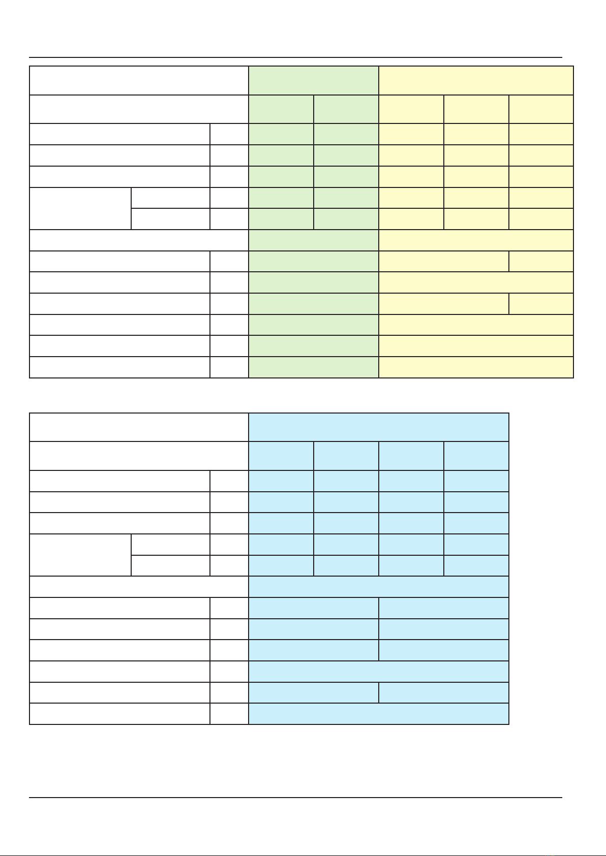
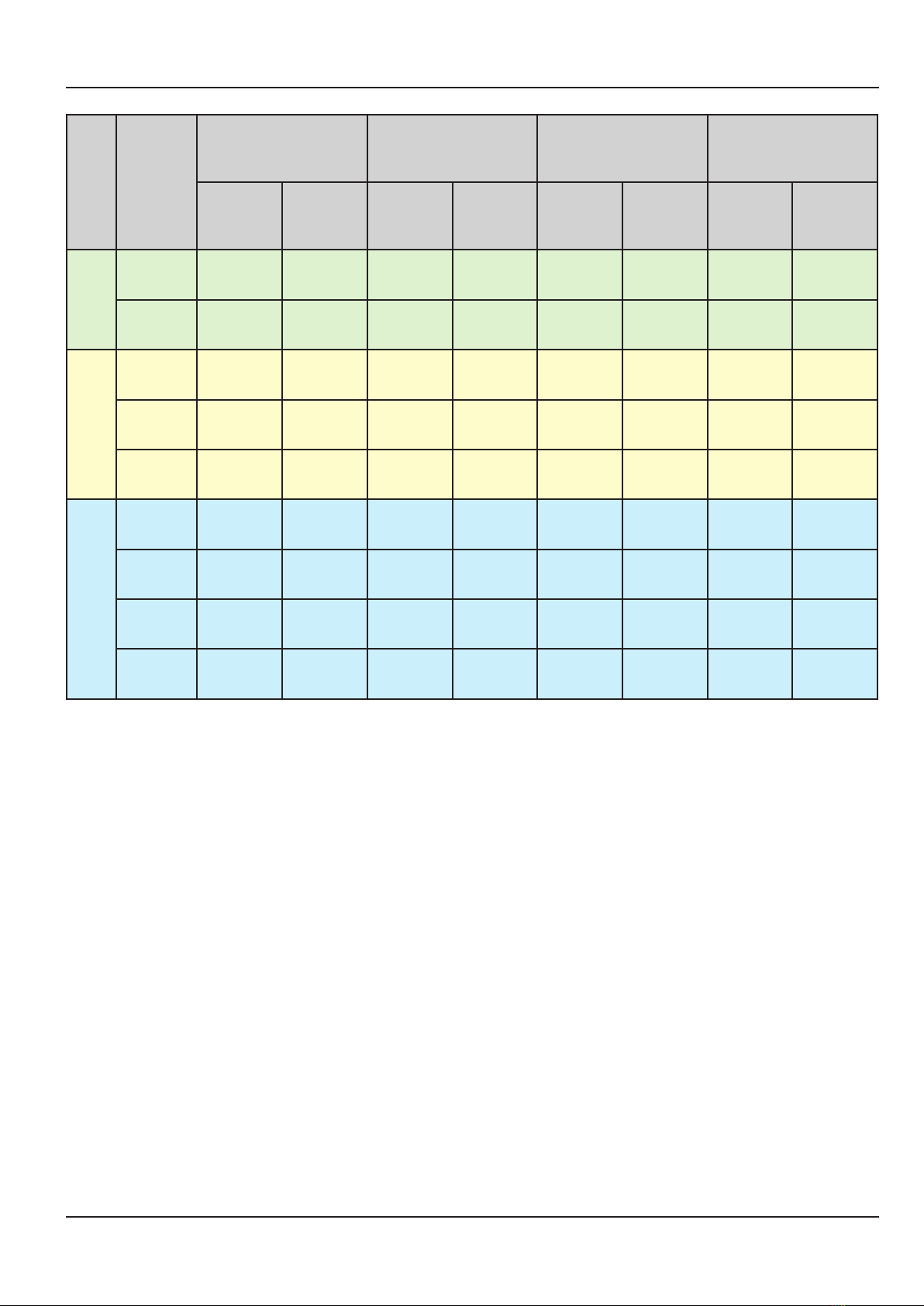
3.2 TECHNICAL FEATURES OF THE COMBUSTION UNIT . . . . . . . . . . . . . . . . . . . . . .7
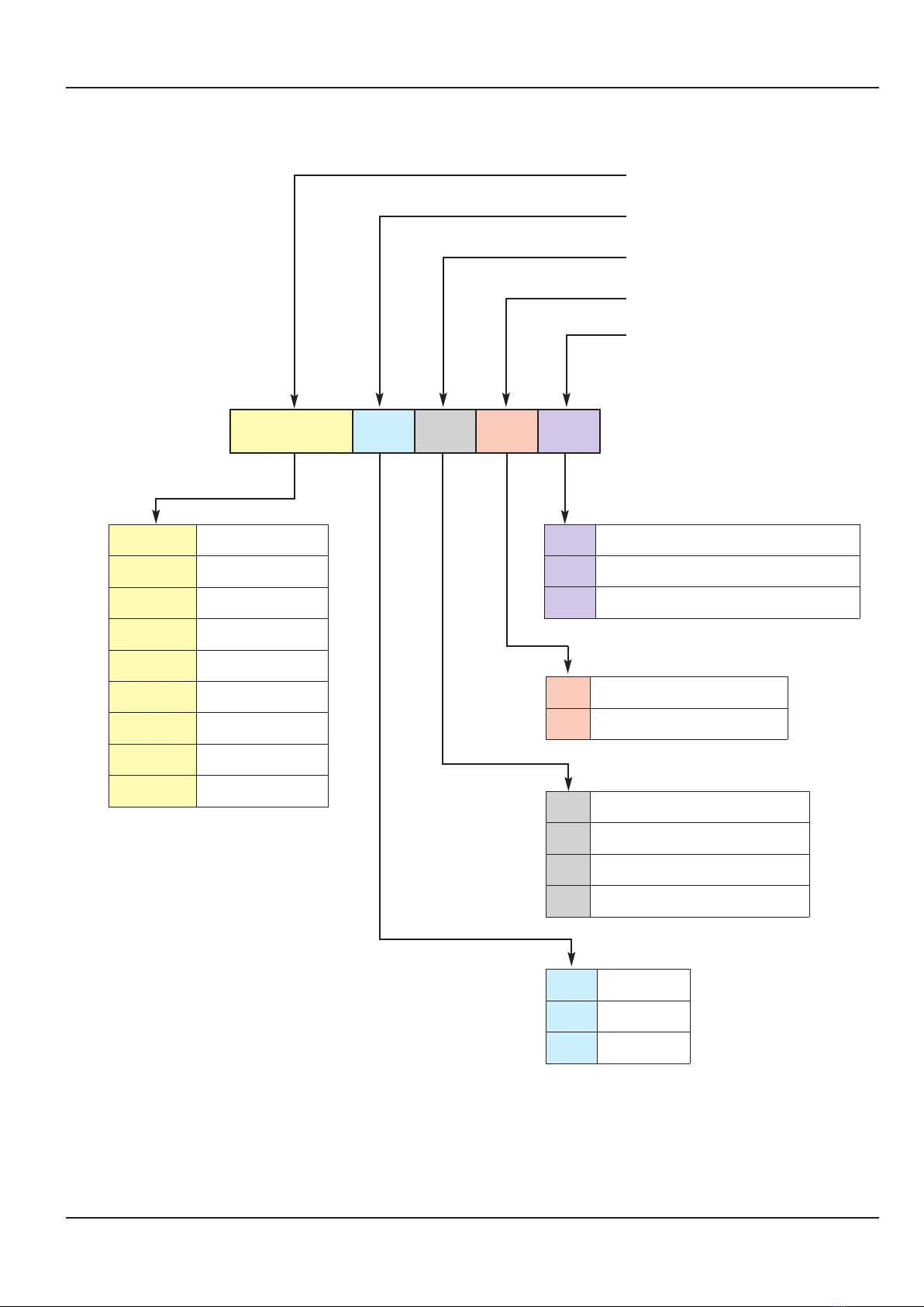
3.2.1 Code table . . . . . . . . . . . . . . . . . . . . . . . . . . . . . . . . . . . . . . . . . . . . . . . . . . . . . . . . . . . . . . . .7
3.2.3 Features of the generator components . . . . . . . . . . . . . . . . . . . . . . . . . . . . . . . . . . . . . . . . .10
3.2.2 Main components in the generator . . . . . . . . . . . . . . . . . . . . . . . . . . . . . . . . . . . . . . . . . . . .10
3.3 EXPLOSION OF THE THERMAL UNIT . . . . . . . . . . . . . . . . . . . . . . . . . . . . . . . . . .12
3.4 DIMENSIONS OF THE GENERATOR . . . . . . . . . . . . . . . . . . . . . . . . . . . . . . . . . . .14
3.5 DIMENSIONS OF THE RADIANT BAND . . . . . . . . . . . . . . . . . . . . . . . . . . . . . . . . .15
3.6 OHA 100, OHA 200, OHA 400 COMBUSTION HEAD . . . . . . . . . . . . . . . . . . . . . . .16
3.6.1 Diaphragm and electrode positions . . . . . . . . . . . . . . . . . . . . . . . . . . . . . . . . . . . . . . . . . . . .19
4 INSTALLATION . . . . . . . . . . . . . . . . . . . . . . . . . . . . . . . . . . . . . . . . . . .20
4.1 INSTALLATION AREA AND SAFETY DISTANCE . . . . . . . . . . . . . . . . . . . . . . . . . .20
4.2 MINIMUM DISTANCE BETWEEN THE OHA RADIANT BAND AND INFLAMMABLE
MATERIALS . . . . . . . . . . . . . . . . . . . . . . . . . . . . . . . . . . . . . . . . . . . . . . . . . . . . . . .20
4.3 ASSEMBLY SEQUENCE FOR THE BAND . . . . . . . . . . . . . . . . . . . . . . . . . . . . . . .21
4.4 MODULAR PLATFORM . . . . . . . . . . . . . . . . . . . . . . . . . . . . . . . . . . . . . . . . . . . . . .23
4.4.1 Platform composition . . . . . . . . . . . . . . . . . . . . . . . . . . . . . . . . . . . . . . . . . . . . . . . . . . . . . . .23
4.4.2 Assembling the standard platform (without glass fixing bracket kit and panel support kit
REI120) . . . . . . . . . . . . . . . . . . . . . . . . . . . . . . . . . . . . . . . . . . . . . . . . . . . . . . . . . . . . . . . . .25
4.4.3 Hole for platform with glass holder kit and REI120 panel support kit . . . . . . . . . . . . . . . . . .29
4.5 ASSEMBLING THE HEATING UNIT ON THE PLATFORM . . . . . . . . . . . . . . . . . . .29
4.6 TILTED BRACKET FOR ROOF UNIT . . . . . . . . . . . . . . . . . . . . . . . . . . . . . . . . . . . .30
4.7 CONNECTING THE COMBUSTION CHAMBER EXTENSION . . . . . . . . . . . . . . . .31
4.8 CONNECTING THE COMBUSTION UNIT TO THE BAND . . . . . . . . . . . . . . . . . . .32
4.9 ASSEMBLING THE BANDS . . . . . . . . . . . . . . . . . . . . . . . . . . . . . . . . . . . . . . . . . . .34
4.9.1 Side connections . . . . . . . . . . . . . . . . . . . . . . . . . . . . . . . . . . . . . . . . . . . . . . . . . . . . . . . . . .36
4.9.2 Connections between pipes . . . . . . . . . . . . . . . . . . . . . . . . . . . . . . . . . . . . . . . . . . . . . . . . .37
4.9.3 Mounting the curves . . . . . . . . . . . . . . . . . . . . . . . . . . . . . . . . . . . . . . . . . . . . . . . . . . . . . . .39
4.9.4 Mounting the expansion joins . . . . . . . . . . . . . . . . . . . . . . . . . . . . . . . . . . . . . . . . . . . . . . . .41
4.9.5 90° Side connections . . . . . . . . . . . . . . . . . . . . . . . . . . . . . . . . . . . . . . . . . . . . . . . . . . . . . . .44
4.9.6 Assembling the end closed cover . . . . . . . . . . . . . . . . . . . . . . . . . . . . . . . . . . . . . . . . . . . . .45
4.9.7 Asembling the “T” branch . . . . . . . . . . . . . . . . . . . . . . . . . . . . . . . . . . . . . . . . . . . . . . . . . . .46
4.9.8 Assembling the top insulation . . . . . . . . . . . . . . . . . . . . . . . . . . . . . . . . . . . . . . . . . . . . . . . .47
4.9.9 Vertical connections for the radiant band positioned on two different levels . . . . . . . . . . . . .50
4.9.10 Assembling the bottom grid (optional) . . . . . . . . . . . . . . . . . . . . . . . . . . . . . . . . . . . . . . . . . .51
4.9.11 Assembling the top shell (optional) . . . . . . . . . . . . . . . . . . . . . . . . . . . . . . . . . . . . . . . . . . . .52
4.9.12 Assembling the reflecting sides (optional) . . . . . . . . . . . . . . . . . . . . . . . . . . . . . . . . . . . . . . .53

4
Rev. 16GB1304
SYSTEMA S.p.A. OHA
4.10 INSTALLING THE RADIANT BAND WITH THE ADDITIONAL REFLECTING SIDE 54
5 GAS PIPING . . . . . . . . . . . . . . . . . . . . . . . . . . . . . . . . . . . . . . . . . . . . .55
6 ELECTRIC WIRING . . . . . . . . . . . . . . . . . . . . . . . . . . . . . . . . . . . . . . . .56
6.1 WIRING DIAGRAM FOR THE COMBUSTION UNIT TO THE GROUND CONTROL
BOARD SLIM2 AND SYS2 . . . . . . . . . . . . . . . . . . . . . . . . . . . . . . . . . . . . . . . . . . . .56
7 TESTING AND START UP . . . . . . . . . . . . . . . . . . . . . . . . . . . . . . . . . .57
7.1 PRELIMINARY PROCEDURES FOR AUTOMATIC IGNITION . . . . . . . . . . . . . . . .57
7.1.1 Ignition phases for the combustion unit . . . . . . . . . . . . . . . . . . . . . . . . . . . . . . . . . . . . . . . . .58
7.2 AIR DAMPER REGULATION . . . . . . . . . . . . . . . . . . . . . . . . . . . . . . . . . . . . . . . . . .59
7.4 SETTING THE AIR-DIFFERENTIAL PRESSURE SWITCH . . . . . . . . . . . . . . . . . . .60
7.3 GAS PRESSURE REGULATION . . . . . . . . . . . . . . . . . . . . . . . . . . . . . . . . . . . . . . .60
8 MAINTENANCE . . . . . . . . . . . . . . . . . . . . . . . . . . . . . . . . . . . . . . . . . . .61
8.1 CHANGING THE FUEL . . . . . . . . . . . . . . . . . . . . . . . . . . . . . . . . . . . . . . . . . . . . . . .61
8.1.1 Transformation from Natural gas to LPG gas . . . . . . . . . . . . . . . . . . . . . . . . . . . . . . . . . . . .61
8.1.2 Transformation from LPG gas to Natural gas for OHA 300 . . . . . . . . . . . . . . . . . . . . . . . . . .62
8.2 OPERATING FAULTS . . . . . . . . . . . . . . . . . . . . . . . . . . . . . . . . . . . . . . . . . . . . . . . .64
9 GUARANTEE . . . . . . . . . . . . . . . . . . . . . . . . . . . . . . . . . . . . . . . . . . . .66
9.1 GUARANTEE COVER AND VALIDITY . . . . . . . . . . . . . . . . . . . . . . . . . . . . . . . . . . .66
9.2 ITEMS NOT COVERED BY THE GUARANTEE . . . . . . . . . . . . . . . . . . . . . . . . . . .66
9.3 RESPONSABILITY . . . . . . . . . . . . . . . . . . . . . . . . . . . . . . . . . . . . . . . . . . . . . . . . . .67
9.4 GUARANTEE EFFECTIVENES AND ENFORCEMENT . . . . . . . . . . . . . . . . . . . . .67
9.5 LIABILITY . . . . . . . . . . . . . . . . . . . . . . . . . . . . . . . . . . . . . . . . . . . . . . . . . . . . . . . . .67
9.6 LEGAL CONTROVERSIES - TERRITORIAL JURISDICTION AND RIGHTS OF THE
PARTIES . . . . . . . . . . . . . . . . . . . . . . . . . . . . . . . . . . . . . . . . . . . . . . . . . . . . . . . . . .67
10 SETTING ASIDE . . . . . . . . . . . . . . . . . . . . . . . . . . . . . . . . . . . . . . . . . .67
11 CE CERTIFICATE . . . . . . . . . . . . . . . . . . . . . . . . . . . . . . . . . . . . . . . . .68

5Rev. 16GB1304
SYSTEMA S.p.A.OHA
Before using the appliance, read this manual carefully.
The instructions given herein must be scrupulously followed, especially with regards the safety standards.
Systema declines all responsibility for direct or indirect damage caused to people, animals and property by
failure to observe the instructions given herein.
ATTENTION ! !
•This instruction manual is an integral and important part of the radiant band and must be kept in a safe
place nearby for rapid consultation.
•Please read the instructions and warnings given in the manual carefully, as they give you important infor-
mation regarding safety, installation, use and maintenance.
•If you lose this manual, please contact the manufacturer for a new one.
•This unit has been designed for heating large work areas, like industrial sheds and artisan workshops,
warehouses, areas with extensive air exchange, loading bays outside sheds, sports facilities, gymna-
siums. As it works with the heat radiation principle; it can be used for heating single areas or for heating
the entire room.
•The unit cannot be used to heat artisan or industrial areas where the processes and materials used carry
the risk of gas, vapour or dust formation which could cause fires or explosions.
•The unit must only be installed by professionally qualified persons, fully respecting current legislation in
force. The manufacturer declines all liability for damage caused due to faulty installation or improper and
incorrect use of the radiant band.
•The gas adduction plant and electric connections must be made in accordance with national and local
regulations in force in the country where the appliance is installed.
•The unit must be started by a qualified person the first time.
•If the radiant band stops or does not work properly, turn it off immediately. Any parts must be repaired or
replaced by a qualified person, using only original spare parts. Failure to do so could make the unit unsa-
fe to use.
•To get the best performance from the radiant band, the manufacturer's instructions must be followed in
full and a full maintenance check must be performed at least once a year by a qualified person.
•The packing material (nylon, foam polystyrol, wood, staples, etc.) must not be left lying around within the
reach of children, as they are potentially dangerous and also polluting, they must be collected and dispo-
sed of in accordance with current legislation.
•If the unit changes hands, or a new tenant enters the premises, all the documentation relative to the
radiant band must be handed over to the new owner.
1 GENERAL STANDARDS
2 PACKING
2.1 PACKING LIST
1) Combustion chamber complete with terminal and electric board are delivered packed on a pallet, wrap-
ped in nylon film.
2) Radiant band is delivered loose, the pipe is supplied in sections of 6 meters long and packed; the insula-
tion is in nylon bags, all the accessories (bends, brackets, sides, etc.) are packed on pallets and wrapped
in nylon film.

6
Rev. 16GB1304
SYSTEMA S.p.A. OHA
3.1 OPERATING DESCRIPTION AND FEATURES
OHA radiant bands are composed of a suspended combustion chamber on the outside and a radiant band
installed inside the room to be heated.
The combustion chamber generates heat through a gas burner, and the vector fluid is constantly recycled
by a fan inside the airtight radiant band which is depressed with respect to the heated area.
The variable temperature heat vector fluid is recycled fuel gas, which heats up the stainles steel combustion
chamber and mixes with the new fuel gas produced by the burner;; both these phases take place on the out-
side. A special pressurised manifold, mounted on the outside, eliminates a part of the burnt mixture through
the flue pipe, equivalent in mass to the amount of fuel supporter air and gas that enter the burner.
The temperature of the radiant pipes can vary between a minimum of 150°C and a max. of 300°C, depen-
ding on the project. We recommend installing a limit thermostat to allow setting the max. surface tempera-
ture of the pipes at levels based on the height the radiant band is installed and the type of processes and
materials contained in the premises.
An electric command and control system operates with detection probes to guarantee correct operations of
the heat generation processes in the combustion chamber, of heat exchange and airtightness of the radiant
band inside the room, depression in the entire radiant unit and the discharge of the burnt gases through the
exhaust pipe.
The comfortable level inside the premises depends on both the air temperature and the average radiated
temperature and is set by the globe thermostat probes inside the room, which, through the electric command
and control board, trigger on the operations of each single burner, changing the heat delivery (two stage
regulation) and controlling ignition and they turn off on the basis of the outside temperature and/or the wor-
king hours.
3TECHNICAL FEATURE

7Rev. 16GB1304
SYSTEMA S.p.A.OHA
3.2 TECHNICAL FEATURES OF THE COMBUSTION UNIT
3.2.1 Code table
OH10050 Oha 100-50 kW
OH10100 Oha 100-100 kW
OH20115 Oha 200-115 kW
OH20150 Oha 200-150 kW
OH20180 Oha 200-180 kW
OH40200 Oha 400-200 kW
OH40250 Oha 400-250 kW
OH40300 Oha 400-300 kW
OH40400 Oha 400-400 kW
Tab. 3.1 Oha combustion unit code
MT Natural gas
PB GPL
GS Diesel oil
MManual air lock
AAutomatic air lock
SStandard combustion chamber
4Combustion chamber with 45° curve
9Combustion chamber with 90° curve
IT Standard version
MD Modulating (only Oha 400)
N4 Oha 400-300 with hose Ø 400
PL Long plenum
Example: OH20180 MT IT M S
Thermal unit model Oha 200 (OH20), thermal capacity 180 kW (180), feed natural gas
(MT), standard version (IT), manual air lock (M), standard combustion chamber (S)
N.B. no spaces must be left in the codes: OH20180MTITMS
Combustion chamber type
Air lock type
Version
Type of fuel
Model, unit and thermal capacity

8
Rev. 16GB1304
SYSTEMA S.p.A. OHA
Tab. 3.2a Features of the Oha combustion unit
Categories
GB . . . . . . . . . . . . . . . . . . . . .II2H3P
MODEL OHA 400
VERSION OHA400-200 OHA400-250 OHA400-300 OHA400-400
Thermal capacity kW (Hi)200 250 300 400
Thermal power kW (Hi)183,0 230,0 276,0 366,0
Combustion efficiency average %91,5 92,0% 92,0% 91,5%
Rated CONSUMPTION
at 15°C and 1013 25
mbar
Natural gas G20 Nm³/h 21,16 26,46 31,75 42,33
LPG Propane G31 kg/h 15,54 19,42 23,31 31,07
Alimentazione elettrica 3/N/PE R50Hz 400V
Absorbed electric power W4450 5700
Gas attachment (male) Inches 1” 1”
Appliance weight kg 240 260
Flue gas exhaust pipe diameter mm 200
Max length flue gas exhaust pipe m6 9
Appliance type B22
MODEL OHA 100 OHA 200
VERSION OHA100-50 OHA100-100 OHA200-115 OHA200-150 OHA200-180
Thermal capacity kW (Hi)50 100 115 150 180
Thermal power kW (Hi)45,5 93,0 105,2 138,0 165,6
Combustion efficiency average %91,0 93,0 91,5 92,0 92,0%
Rated CONSUMPTION
at 15°C and 1013 25
mbar
Natural gas G20 Nm³/h 5,29 10,58 12,17 15,87 19,05
LPG Propane G31 kg/h 3,88 7,77 8,93 11,65 13,98
Electric power supply 3/N/PE R50Hz 400V 3/N/PE R50Hz 400V
Absorbed electric power W1350 3450 4450
Gas attachment (male) Inches 1” 1”
Appliance weight kg 90 230 240
Flue gas exhaust pipe diameter mm 200 200
Max length flue gas exhaust pipe m6 6
Appliance type B22 B22
Tab. 3.2b Features of the Oha combustion unit

9Rev. 16GB1304
SYSTEMA S.p.A.OHA
Tab. 3.3 Maximum circuit lengths according to the combustion unit
Model
Thermal
capacity
[kW]
Band model M
1 tube Ø 300 mm
Band model U
2 tube Ø 200 mm
Band model U
2 tube Ø 300 mm
Band model U
2 tube Ø 400 mm
Min.
length (*)
Max.
length (*)
Min.
length (*)
Max.
length (*)
Min.
length (*)
Max.
length (*)
Min.
length (*)
Max.
length (*)
OHA 100
50 40 60 25 35 -- --
100 60 120 35 50 -- --
OHA 200
115 80 130 50 70 -- --
150 115 140 60 80 -- --
180 140 180 80 110 -- --
OHA 400
200 160 190 90 115 -- --
250 190 220 110 130 -- --
300 220 250 130 160 90 120
400 -- -- 120 160
(*) Virtual length = effective length of the radiant band, increased by the equivalent lengths of
direction change of 6 meters for each variation at 90° and 9 meters for the final curve of 180°
and T-branch off.

10
Rev. 16GB1304
SYSTEMA S.p.A. OHA
3.2.3 Features of the generator components
EXCHANGE BOARD
Code . . . . . . . . . . . . . . . . . . . . . . . . . . . . . . . . . . . . . . . . . . . . . . . . . . .00CEAP0776
Electric power supply . . . . . . . . . . . . . . . . . . . . . . . . . . . . . . . . . . . . . .220/240V 50 Hz
Working temperature . . . . . . . . . . . . . . . . . . . . . . . . . . . . . . . . . . . . . .-20°C ÷ + 60°C
Pre-washing time . . . . . . . . . . . . . . . . . . . . . . . . . . . . . . . . . . . . . . . . .20 sec
Start up safety delay time . . . . . . . . . . . . . . . . . . . . . . . . . . . . . . . . . . .max 10 sec
Turn off safety delay time . . . . . . . . . . . . . . . . . . . . . . . . . . . . . . . . . . .< 1 sec
PRESSURE SWITCH
Code . . . . . . . . . . . . . . . . . . . . . . . . . . . . . . . . . . . . . . . . . . . . . . . . . . .00CEPR1110
Assembly position . . . . . . . . . . . . . . . . . . . . . . . . . . . . . . . . . . . . . . . . .vertical
Reset point . . . . . . . . . . . . . . . . . . . . . . . . . . . . . . . . . . . . . . . . . . . . . .50÷500 Pa (± 4 Pa)
Pneumatic connection . . . . . . . . . . . . . . . . . . . . . . . . . . . . . . . . . . . . .Ø 6,2 mm
Max. working pressure . . . . . . . . . . . . . . . . . . . . . . . . . . . . . . . . . . . . .5000 Pa
Working temperature . . . . . . . . . . . . . . . . . . . . . . . . . . . . . . . . . . . . . .-30°C ÷ +60°C
ASYNCHRONOUS THREE-PHASE ELECTRIC MOTOR 1,1 kW
Code . . . . . . . . . . . . . . . . . . . . . . . . . . . . . . . . . . . . . . . . . . . . . . . . . . .05CEMO0766
Electric power supply . . . . . . . . . . . . . . . . . . . . . . . . . . . . . . . . . . . . . .400V 50/60 Hz
Electric output . . . . . . . . . . . . . . . . . . . . . . . . . . . . . . . . . . . . . . . . . . . .1,1 kW
Absorbed electric power . . . . . . . . . . . . . . . . . . . . . . . . . . . . . . . . . . . .2,60 A
Motor rpm . . . . . . . . . . . . . . . . . . . . . . . . . . . . . . . . . . . . . . . . . . . . . . .1.400 rpm
3.2.2 Main components in the generator
Description Codice
OHA100-50
OHA100-100
OHA200-115
OHA200-150
OHA200-180
OHA400-200
OHA400-250
OHA400-300
OHA400-400
Control equipment 00CEAP0776
Adjustable air pressure switch 50÷500 Pa 00CEPR1110
Motor 1,1 kW 1.400 rpm + fan wheel Ø 330 x H 140 05ASMO0100
Motor 3 kW 2.820 rpm + fan wheel Ø 330 x H 100 05ASMO0101
Motor 4 kW 2.880 rpm + fan wheel Ø 330 x H 115 05ASMO0102
Motor 5,5 kW 2900 rpm + fan wheel Ø 330 x H 140 05ASMO0103
Solenoid valve 3/4 05CEGV2506
Solenoid valve 1" 05CEGV2507
Tab.3.4

11 Rev. 16GB1304
SYSTEMA S.p.A.OHA
ASYNCHRONOUS THREE-PHASE ELECTRIC MOTOR 3 kW
Code . . . . . . . . . . . . . . . . . . . . . . . . . . . . . . . . . . . . . . . . . . . . . . . . . . .05CEMO0763
Electric power supply . . . . . . . . . . . . . . . . . . . . . . . . . . . . . . . . . . . . . .400V 50/60 Hz
Electric output . . . . . . . . . . . . . . . . . . . . . . . . . . . . . . . . . . . . . . . . . . . .3 kW
Absorbed electric power . . . . . . . . . . . . . . . . . . . . . . . . . . . . . . . . . . . .6,1 A
Motor rpm . . . . . . . . . . . . . . . . . . . . . . . . . . . . . . . . . . . . . . . . . . . . . . .2820 rpm
ASYNCHRONOUS THREE-PHASE ELECTRIC MOTOR 4 kW
Code . . . . . . . . . . . . . . . . . . . . . . . . . . . . . . . . . . . . . . . . . . . . . . . . . . .05CEMO2633
Electric power supply . . . . . . . . . . . . . . . . . . . . . . . . . . . . . . . . . . . . . .400V 50/60 Hz
Electric output . . . . . . . . . . . . . . . . . . . . . . . . . . . . . . . . . . . . . . . . . . . .4 kW
Absorbed electric power . . . . . . . . . . . . . . . . . . . . . . . . . . . . . . . . . . . .7,88 A
Motor rpm . . . . . . . . . . . . . . . . . . . . . . . . . . . . . . . . . . . . . . . . . . . . . . .2880 rpm
ASYNCHRONOUS THREE-PHASE ELECTRIC MOTOR 5,5 kW
Code . . . . . . . . . . . . . . . . . . . . . . . . . . . . . . . . . . . . . . . . . . . . . . . . . . .05CEMO0761
Electric power supply . . . . . . . . . . . . . . . . . . . . . . . . . . . . . . . . . . . . . .400V 50/60 Hz
Electric output . . . . . . . . . . . . . . . . . . . . . . . . . . . . . . . . . . . . . . . . . . . .5,5 kW
Absorbed electric power . . . . . . . . . . . . . . . . . . . . . . . . . . . . . . . . . . . .10,6 A
Motor rpm . . . . . . . . . . . . . . . . . . . . . . . . . . . . . . . . . . . . . . . . . . . . . . .2900 rpm
SOLENOID VALVE 3/4
Code . . . . . . . . . . . . . . . . . . . . . . . . . . . . . . . . . . . . . . . . . . . . . . . . . . .05CEGV2506
Electric power supply . . . . . . . . . . . . . . . . . . . . . . . . . . . . . . . . . . . . . .230V 50/60 Hz
Electric protection level . . . . . . . . . . . . . . . . . . . . . . . . . . . . . . . . . . . . .IP40
Gas attachment . . . . . . . . . . . . . . . . . . . . . . . . . . . . . . . . . . . . . . . . . .3/4
Operating temperature . . . . . . . . . . . . . . . . . . . . . . . . . . . . . . . . . . . .-10°C ÷ +60°C
SOLENOID VALVE 1”
Code . . . . . . . . . . . . . . . . . . . . . . . . . . . . . . . . . . . . . . . . . . . . . . . . . . .05CEGV2507
Electric power supply . . . . . . . . . . . . . . . . . . . . . . . . . . . . . . . . . . . . . .230V 50/60 Hz
Electric protection level . . . . . . . . . . . . . . . . . . . . . . . . . . . . . . . . . . . . .IP40
Gas attachment . . . . . . . . . . . . . . . . . . . . . . . . . . . . . . . . . . . . . . . . . .1”
Operating temperature . . . . . . . . . . . . . . . . . . . . . . . . . . . . . . . . . . . .-10°C ÷ +60°C

12
Rev. 16GB1304
SYSTEMA S.p.A. OHA
Fig.3.1 Explosion OHA
3.3 EXPLOSION OF THE THERMAL UNIT

13 Rev. 16GB1304
SYSTEMA S.p.A.OHA
Tab.3.5
Pos.
Description Q.ty
1
Plenum
1
2
Female-M8 eyebolt
4
3
Bottom collar
1
4
Top collar
1
5
Top outside panel
1
6
Machine body
1
7
Sealing frame
1
8
Right side external panel
1
9
Sheath clamp Ø 35 mm
1
10
Sheath clamp Ø 35 mm (nut)
1
11
Combustion chamber 1
12
Motor complete with impeller and flange
1
13
Door panel
1
14
Threaded bar for door
2
15
On-board electric control panel with door lock selection switch
1
16
Air lock
1
17
Gas diaphragm 1
18
Combustion head 1
19
Combustion cone 1
20
Bottom external panel 1
21
Panel supporting frame 1
22
Gas pipe disk 1
23
Hole cover 1
24
Left side external panel 1
25
Solenoid valve assembly 1

14
Rev. 16GB1304
SYSTEMA S.p.A. OHA
3.4 DIMENSIONS OF THE GENERATOR
FRONT VIEW SIDE VIEW
SIDE VIEW
Fig.3.2 External dimensions of the OHA heating unit
Gas supply Electricity
supply
Height
Dimension [mm]
Height
Dimension [mm]
Unit with pipe
Ø 300 mm
Unit with pipe
Ø 400 mm
Unit with pipe
Ø 300 mm
Unit with pipe
Ø 400 mm
A
1075
N
1292
B
359
O
740
C
200
P
493
D
664
Q
142
E
333
430
R
637
F
774
923
S
426
475
G
157
67
T
162
113
H
134
70
U
300
400
I
398
319
V
344
352
L
333
430
X
1049
M
333
302
Y
1202
N.B. for units with long plenum, the P and N heights can be respectively 1003 and 1802 mm

15 Rev. 16GB1304
SYSTEMA S.p.A.OHA
3.5 DIMENSIONS OF THE RADIANT BAND
Fig.3.3 Overall dimensions of the band
Tab.3.7
Example: weight of mod. U 300 radiant strip with upper plate and lower protection net
Total weight for meter = 28 + 4,0 + 2,0 = 34,0 kg/m
Dimensions
Level
1 pıpe 2 pıpe 2 pıpe
A
Ø300 Ø300 Ø400
B
- 335 460
C
512 850 1020
D
580 918 1088
E
374 374 478
Weight (kg/m)
19 28 35
Weight (kg/m)
upper plate
2,5 4,0 4,8
Weight (kg/m)
protectıon grıd
1,2 2,0 2,3

16
Rev. 16GB1304
SYSTEMA S.p.A. OHA
Tab.3.8
OHA 100
U.M. Natural gas G20 LPG G30/G31
Thermal capacity kW 50
Cone diameter mm 70
Combustion chamber diameter mm 204
Combustion chamber extended diameter mm 204
Combustion head code mm 05CNTO2506
Number of additional injectors N. Without injectors
Combustion chamber depression mbar 2,5 3
Gas diaphragm diameter mm 7,5 4,5
Pressure at the nozzle mbar 15 36
Thermal capacity kW 100
Cone diameter mm 70
Combustion chamber diameter mm 204
Combustion chamber extended diameter mm 204
Combustion head code 05CNTO2506
Number of additional injectors N. Without injectors
Combustion chamber depression mbar 2,5 3
Gas diaphragm diameter mm 12 6,5
Pressure at the nozzle mbar 18 36
3.6 OHA 100, OHA 200, OHA 400 COMBUSTION HEAD

17 Rev. 16GB1304
SYSTEMA S.p.A.OHA
Tab.3.9
OHA 200
U.M. Metano G20 GPL G30/G31
Thermal capacity kW 115
Cone diameter mm 80
Combustion chamber diameter mm 168
Combustion chamber extended diameter mm 204
Combustion head code 05CNTO2505 05CNTO2506
Number of additional injectors N. 2 Without injectors
Combustion chamber depression mbar 5 5
Gas diaphragm diameter mm 9 6,5
Pressure at the nozzle mbar 17 33
Thermal capacity kW 150
Cone diameter mm 80
Combustion chamber diameter mm 168
Combustion chamber extended diameter mm 204
Combustion head code 05CNTO2505 05CNTO2506
Number of additional injectors N. 2 Without injectors
Combustion chamber depression mbar 5 5
Gas diaphragm diameter mm 12 7,5
Pressure at the nozzle mbar 14 36
Thermal capacity kW 180
Cone diameter mm 80
Combustion chamber diameter mm 168
Combustion chamber extended diameter mm 204
Combustion head code 05CNTO2505
Number of additional injectors N. 2
Combustion chamber depression mbar 5 5
Gas diaphragm diameter mm 13 8
Pressure at the nozzle mbar 15 36

18
Rev. 16GB1304
SYSTEMA S.p.A. OHA
Tab.3.10
OHA 400
U.M. Metano G20 GPL G31
Thermal capacity kW 200
Cone diameter mm 120
Combustion chamber diameter mm 204
Combustion chamber extended diameter mm 204
Combustion head code 05CNTO2505
Number of additional injectors N. 2
Combustion chamber depression mbar 5 5
Gas diaphragm diameter mm 13 7,5
Pressure at the nozzle mbar 9 31
Thermal capacity kW 250
Cone diameter mm 120
Combustion chamber diameter mm 204
Combustion chamber extended diameter mm 204
Combustion head code 05CNTO2508 05CNTO2505
Number of additional injectors N. 4 2
Combustion chamber depression mbar 5 5
Gas diaphragm diameter mm 15 8,5
Pressure at the nozzle mbar 6 31
Thermal capacity kW 300
Cone diameter mm 120
Combustion chamber diameter mm 204
Combustion chamber extended diameter mm 204
Combustion head code 05CNTO2508 05CNTO2505
Number of additional injectors N. 4 2
Combustion chamber depression mbar 5 5
Gas diaphragm diameter mm 18 10
Pressure at the nozzle mbar 5 31
Thermal capacity kW 400
Cone diameter mm Without cone 120
Combustion chamber diameter mm 204
Combustion chamber extended diameter mm 204
Combustion head code 05CNTO2508 05CNTO2505
Number of additional injectors N. 4 2
Combustion chamber depression mbar 5 5
Gas diaphragm diameter mm Without diaphragm 11,5
Pressure at the nozzle mbar 5 30

19 Rev. 16GB1304
SYSTEMA S.p.A.OHA
DIAPHRAGM
Fig. 3.4 Diaphragm position Fig. 3.5 Combustion head with electrode
positions
3.6.1 Diaphragm and electrode positions

20
Rev. 16GB1304
SYSTEMA S.p.A. OHA
Radiating pipes
Fig.4.2 Minimum distances between the OHA radiant
band and inflammable materials
4.2 MINIMUM DISTANCE BETWEEN THE OHA RADIANT BAND AND
INFLAMMABLE MATERIALS
The distance between the external surfaces of the radiating pipes and any inflammable materials must be
sufficient to avoid such materials reaching dangerous temperatures, to avoid fires developing or combu-
stion reactions. In all circumstances it must be at least 1.5 meters.
Remember that the max. surface temperature of the
radiating pipes can be set and controlled at any level
between 150° - 300°C.
OHA Radiant band
Insulation min.
3 cm thick
Protection plate (stainless steel, galvani-
sed plate, aluminium)
which must give an air passage sufficient
for ventilating the electric motor
Electric motor
Roof
OVERHEAD TRAVELLING CRANE
Fig.4.1 Protection for the overhead travelling crane
4.1 INSTALLATION AREA AND SAFETY DISTANCE
4 INSTALLATION
This manual suits for next models
2
Table of contents
Other Systema Heater manuals